kombk.book Page i Tuesday, June 29, 1999 3:25 PM Software Release V1.3.0 Part No.
kombk.book Page ii Tuesday, June 29, 1999 3:25 PM Copyright © 1999 Nortel Networks All rights reserved. Printed in the USA. July 1999. The information in this document is subject to change without notice. The statements, configurations, technical data, and recommendations in this document are believed to be accurate and reliable, but are presented without express or implied warranty. Users must take full responsibility for their applications of any products specified in this document.
kombk.book Page iii Tuesday, June 29, 1999 3:25 PM EC Declaration of Conformity This product conforms (or these products conform) to the provisions of Council Directive 89/336/EEC and 73/23/EEC. The Declaration of Conformity is available on the Nortel Networks World Wide Web site at http://libra2.corpwest.baynetworks.com/cgi-bin/ndCGI.exe/DocView/.
kombk.book Page iv Tuesday, June 29, 1999 3:25 PM Nortel Networks NA Inc. Software License Agreement NOTICE: Please carefully read this license agreement before copying or using the accompanying software or installing the hardware unit with pre-enabled software (each of which is referred to as “Software” in this Agreement). BY COPYING OR USING THE SOFTWARE, YOU ACCEPT ALL OF THE TERMS AND CONDITIONS OF THIS LICENSE AGREEMENT.
kombk.book Page v Tuesday, June 29, 1999 3:25 PM Licensee is responsible for the security of its own data and information and for maintaining adequate procedures apart from the Software to reconstruct lost or altered files, data, or programs. 4. Limitation of liability.
kombk.
kombk.book Page vii Tuesday, June 29, 1999 3:25 PM Contents Preface Audience ..........................................................................................................................xxi Organization ...................................................................................................................xxii Text Conventions ........................................................................................................... xxiii Acronyms ..................................
kombk.book Page viii Tuesday, June 29, 1999 3:25 PM Port Mirroring .........................................................................................................1-16 Autosensing and Autonegotiation ...........................................................................1-16 BootP Automatic IP Configuration/MAC Address ...................................................1-17 SNMP MIB Support ................................................................................................
kombk.book Page ix Tuesday, June 29, 1999 3:25 PM MultiLink Trunks ............................................................................................................1-57 Client/Server Configuration Using MultiLink Trunks ...............................................1-58 Trunk Configuration Screen Examples ...................................................................1-60 Trunk Configuration Screen for Switch S1 .......................................................
kombk.book Page x Tuesday, June 29, 1999 3:25 PM Chapter 3 Using the Console Interface Accessing the CI Menus and Screens ............................................................................3-1 Using the CI Menus and Screens ...................................................................................3-2 Navigating the CI Menus and Screens .....................................................................3-2 Screen Fields and Descriptions ...................................................
kombk.book Page xi Tuesday, June 29, 1999 3:25 PM Renumber Stack Units ..................................................................................................3-65 Hardware Unit Information ............................................................................................3-67 Spanning Tree Configuration ........................................................................................3-67 Spanning Tree Port Configuration ............................................................
kombk.book Page xii Tuesday, June 29, 1999 3:25 PM Electromagnetic Immunity ............................................................................................. A-3 Declaration of Conformity .............................................................................................. A-4 Appendix B Gigabit Fiber Optical Characteristics 1000BASE-SX Models .................................................................................................. B-1 Operating Range .........................
kombk.book Page xiii Tuesday, June 29, 1999 3:25 PM MDI-X to MDI-X Cable Connections ....................................................................... E-4 DB-9 (RS-232-D) Console/Comm Port Connector ........................................................
kombk.
kombk.book Page xv Tuesday, June 29, 1999 3:25 PM Figures Figure 1-1. BayStack 450 Switch Versions .................................................................1-1 Figure 1-2. BayStack 450 Switch Front Panels ..........................................................1-2 Figure 1-3. BayStack 450-24T/12T LED Display Panel ..............................................1-5 Figure 1-4. BayStack 450-12F LED Display Panel .....................................................1-6 Figure 1-5.
kombk.book Page xvi Tuesday, June 29, 1999 3:25 PM Figure 1-30. VLAN Configuration Spanning Multiple Switches ..................................1-46 Figure 1-31. IP Multicast Propagation With IGMP Routing ........................................1-49 Figure 1-32. BayStack 450 Switch Filtering IP Multicast Streams (1 of 2) .................1-50 Figure 1-33. BayStack 450 Switch Filtering IP Multicast Streams (2 of 2) .................1-51 Figure 1-34. Prioritizing Packets .....................................
kombk.book Page xvii Tuesday, June 29, 1999 3:25 PM Figure 2-12. Nortel Networks Logo Screen ................................................................2-16 Figure 2-13. Main Menu .............................................................................................2-18 Figure 2-14. IP Configuration/Setup Screen (Standalone Switch) .............................2-19 Figure 2-15. Main Menu (Standalone Switch Example) .............................................2-21 Figure 2-16.
kombk.book Page xviii Tuesday, June 29, 1999 3:25 PM Figure 3-30. Spanning Tree Port Configuration Screen (2 of 2) .................................3-70 Figure 3-31. Spanning Tree Switch Settings Screen ..................................................3-72 Figure 3-32. TELNET Configuration Screen ..............................................................3-75 Figure 3-33. Software Download Screen ...................................................................3-79 Figure 3-34.
kombk.book Page xix Tuesday, June 29, 1999 3:25 PM Tables Table 1-1. BayStack 450 Switch LED Descriptions .................................................1-6 Table 1-2. International Power Cord Specifications ..................................................1-9 Table 2-1. Power-Up Sequence ..............................................................................2-14 Table 3-1. Console Interface Main Menu options .....................................................3-5 Table 3-2.
kombk.book Page xx Tuesday, June 29, 1999 3:25 PM xx Table 3-27. TELNET Configuration Screen Fields ...................................................3-76 Table 3-28. Software Download Screen Fields ........................................................3-79 Table 3-29. LED Indications During the Software Download Process .....................3-81 Table 3-30. Configuration File Download/Upload Screen Fields .............................3-83 Table 3-31.
kombk.book Page xxi Tuesday, June 29, 1999 3:25 PM Preface Congratulations on your purchase of the BayStack 450 switch, part of the Nortel Networks® BayStack 10/100/1000 Switch line of communications products. There are three versions of the BayStack 450 switch: the Model 450-24T, the Model 450-12T, and the Model 450-12F. This guide describes the features, uses, and installation procedures for the three versions.
kombk.
kombk.book Page xxiii Tuesday, June 29, 1999 3:25 PM Preface Text Conventions This guide uses the following text conventions: bold text Indicates command names and options and text that you need to enter. Example: Enter show ip {alerts | routes}. Example: Use the dinfo command. italic text Indicates file and directory names, new terms, book titles, and variables in command syntax descriptions. Where a variable is two or more words, the words are connected by an underscore.
kombk.
kombk.book Page xxv Tuesday, June 29, 1999 3:25 PM Preface You can purchase selected documentation sets, CDs, and technical publications through the collateral catalog. The catalog is located on the World Wide Web at support.baynetworks.com/catalog.html and is divided into sections arranged alphabetically: • The “CD ROMs” section lists available CDs. • The “Guides/Books” section lists books on technical topics. • The “Technical Manuals” section lists available printed documentation sets.
kombk.
kombk.book Page 1 Tuesday, June 29, 1999 3:25 PM Chapter 1 BayStack 450 10/100/1000 Series Switches This chapter introduces the BayStack 450 switch and covers the following topics: • Physical description • Summary of features • Network configuration examples • Overview of main features Physical Description There are three versions of the BayStack 450 switch: the BayStack 450-24T switch, the BayStack 450-12T switch, and the BayStack 450-12F switch (Figure 1-1).
kombk.book Page 2 Tuesday, June 29, 1999 3:25 PM Using the BayStack 450 10/100/1000 Series Switch Front Panel Figure 1-2 shows the front-panel configurations for the three BayStack 450 switch models. Descriptions of the front-panel components follow the figures. For a description of the components located on the back panel of the BayStack 450 switch, see “Back Panel” on page 1-8.
kombk.book Page 3 Tuesday, June 29, 1999 3:25 PM BayStack 450 10/100/1000 Series Switches Comm Port The Comm Port (also referred to as the Console/Comm Port) allows you to access the console interface (CI) screens and customize your network using the supplied menus and screens (see Chapter 3, “Using the Console Interface”). The Console/Comm Port is a DB-9, RS-232-D male serial port connector.
kombk.book Page 4 Tuesday, June 29, 1999 3:25 PM Using the BayStack 450 10/100/1000 Series Switch The 10BASE-T/100BASE-TX port connectors are configured as MDI-X (media-dependent interface-crossover). These ports connect over straight cables to the network interface controller (NIC) card in a node or server, similar to a conventional Ethernet repeater hub.
kombk.book Page 5 Tuesday, June 29, 1999 3:25 PM BayStack 450 10/100/1000 Series Switches LED Display Panel Figure 1-3 shows the BayStack 450-24T and BayStack 450-12T LED display panels. Figure 1-4 shows the BayStack 450-12F LED display panel. See Table 1-1 for a description of the LEDs.
kombk.book Page 6 Tuesday, June 29, 1999 3:25 PM Using the BayStack 450 10/100/1000 Series Switch BayStack 450-12F Switch Pwr Cas Up 1 2 4 3 5 6 7 8 9 10 11 12 Link Status Dwn F Dx RPSU Base Activity BayStack 450-12F = Dual color LED BS45071A Figure 1-4. Table 1-1. BayStack 450-12F LED Display Panel BayStack 450 Switch LED Descriptions Label Type Color State Meaning Pwr Power status Green On DC power is available to the switch’s internal circuitry.
kombk.book Page 7 Tuesday, June 29, 1999 3:25 PM BayStack 450 10/100/1000 Series Switches Table 1-1. Label BayStack 450 Switch LED Descriptions (continued) Type Color State Meaning Amber or Green Blinking Incompatible software revision or unable to obtain a unit ID (Renumber Stack Unit table full). The unit is on the ring but cannot participate in the stack configuration. Off The switch is in standalone mode. Green On The switch is connected to the downstream unit’s Cascade A Out connector.
kombk.book Page 8 Tuesday, June 29, 1999 3:25 PM Using the BayStack 450 10/100/1000 Series Switch Table 1-1. BayStack 450 Switch LED Descriptions (continued) Label Type Color State Meaning 10/100 10/100 Mb/s port speed indicator Green On The corresponding port is set to operate at 100 Mb/s and the link is good. Green Blinking The corresponding port has been disabled by software. Amber On The corresponding port is set to operate at 10 Mb/s and the link is good.
kombk.book Page 9 Tuesday, June 29, 1999 3:25 PM BayStack 450 10/100/1000 Series Switches 1 3 100-240V 47-63Hz~ Cascade Module Redundant Power 1 = AC power receptacle 2 = RPSU connector 3 = Cascade Module Slot 2 BS45004A Figure 1-5. BayStack 450 Switch Back Panel AC Power Receptacle The AC power receptacle accepts the AC power cord (supplied). For installation outside of North America, make sure that you have the proper power cord for your region.
kombk.book Page 10 Tuesday, June 29, 1999 3:25 PM Using the BayStack 450 10/100/1000 Series Switch Table 1-2. International Power Cord Specifications Country/Plug description Specifications U.S.
kombk.book Page 11 Tuesday, June 29, 1999 3:25 PM BayStack 450 10/100/1000 Series Switches Cascade Module Slot The Cascade Module slot allows you to attach an optional BayStack 400-ST1 Cascade Module to the switch (see “Stack Operation” on page 1-23). You can connect up to eight BayStack 450 switches into a redundant stack configuration.
kombk.book Page 12 Tuesday, June 29, 1999 3:25 PM Using the BayStack 450 10/100/1000 Series Switch • Address database size: 16,000 entries at line rate (32,000 entries without flooding) • Fail-Safe Stacking: provides uninterrupted connectivity for up to eight units, with up to 224 ports stacked together as one managed unit (requires one optional BayStack 400-ST1 Cascade Module kit per stacked unit. See your Nortel Networks sales representative for ordering information).
kombk.book Page 13 Tuesday, June 29, 1999 3:25 PM BayStack 450 10/100/1000 Series Switches • TELNET: -- Support for up to four simultaneous TELNET sessions -- Optional password protection -- Login time-out -- Failed-login guard -- Inactivity time-out -- Allowed source addresses -- Event logging • IEEE 802.
kombk.book Page 14 Tuesday, June 29, 1999 3:25 PM Using the BayStack 450 10/100/1000 Series Switch • MultiLink Trunking, supporting: -- Switch-to-switch trunks -- Switch-to-server trunks • Port mirroring (conversation steering) -- Port-based -- MAC address-based • Configuration file download/upload support: allows you to store your switch/ stack configuration parameters on a TFTP server. • Remote monitoring (RMON), with four groups integrated: -- Statistics -- History -- Alarms -- Events IEEE 802.
kombk.book Page 15 Tuesday, June 29, 1999 3:25 PM BayStack 450 10/100/1000 Series Switches IGMP Snooping Feature For conserving bandwidth and controlling IP Multicast, the IGMP snooping feature can provide the same benefit as IP Multicast routers, but in the local area. For more information about the IGMP snooping feature, see “IGMP Snooping” on page 1-48. Flash Memory Storage Storage of Switch Software Image The BayStack 450 switch uses flash memory to store the switch software image.
kombk.book Page 16 Tuesday, June 29, 1999 3:25 PM Using the BayStack 450 10/100/1000 Series Switch MultiLink Trunking The MultiLink Trunking feature allows you to group multiple ports (up to four) together when forming a link to another switch or server, thus increasing aggregate throughput of the interconnection between two devices, up to 800 Mb/s in full-duplex mode. BayStack 450 switches can be configured with up to six MultiLink Trunks.
kombk.book Page 17 Tuesday, June 29, 1999 3:25 PM BayStack 450 10/100/1000 Series Switches When autonegotiation-capable devices are attached to the BayStack 450 switch, the switch ports negotiate down from 100 Mb/s speed and full-duplex mode until the attached device acknowledges a supported speed and duplex mode. For more information about autosensing and autonegotiation modes, see “Autonegotiation Modes” on page 4-8.
kombk.book Page 18 Tuesday, June 29, 1999 3:25 PM Using the BayStack 450 10/100/1000 Series Switch SNMP MIB Support The BayStack 450 switch supports an SNMP agent with industry standard MIBs, as well as private MIB extensions, which ensures compatibility with existing network management tools. The BayStack 450 switch supports the MIB-II (RFC 1213), Bridge MIB (RFC 1493), and the RMON MIB (RFC 1757), which provide access to detailed management statistics.
kombk.book Page 19 Tuesday, June 29, 1999 3:25 PM BayStack 450 10/100/1000 Series Switches Note: All models of the BayStack 450 switch can be used interchangeably in the following network configuration examples. Desktop Switch Application Figure 1-6 shows a BayStack 450-24T switch used as a desktop switch, where desktop workstations are connected directly to switch ports. This configuration provides dedicated 100 Mb/s connections to the network center, to the server, and up to 26 users.
kombk.book Page 20 Tuesday, June 29, 1999 3:25 PM Using the BayStack 450 10/100/1000 Series Switch Segment Switch Application Figure 1-7 shows a BayStack 450-24T switch used as a segment switch to alleviate user contention for bandwidth and eliminate server and network bottlenecks. Before segmentation, 88 users had a total bandwidth of only 10 Mb/s available. After segmentation, 92 users have 40 Mb/s, four times the previous bandwidth, while adding 22 dedicated 100 Mb/s connections.
kombk.book Page 21 Tuesday, June 29, 1999 3:25 PM BayStack 450 10/100/1000 Series Switches High-Density Switched Workgroup Application Figure 1-8 shows an example of using a BayStack 450 switch with a high-speed (gigabit) connection to a Nortel Networks Accelar™ 1100 switch. BayStack 303 and 304 switches are also shown in this example of a high-density switched workgroup.
kombk.book Page 22 Tuesday, June 29, 1999 3:25 PM Using the BayStack 450 10/100/1000 Series Switch Fail-Safe Stack Application Figure 1-9 shows an example of eight BayStack 450 switches that are stacked together as a single managed unit. If any single unit in the stack fails, the remaining stack remains operational, without interruption.
kombk.book Page 23 Tuesday, June 29, 1999 3:25 PM BayStack 450 10/100/1000 Series Switches Stack Operation BayStack 450 switches that are configured with BayStack 450 software version V1.1.0 or later provide fail-safe stackability when you install the optional BayStack 400-ST1 Cascade Module. You can connect up to eight switches to provide uninterrupted connectivity for up to 224 ports (see “Fail-Safe Stack Application” on page 1-22). The entire stack is manageable as a single unit.
kombk.book Page 24 Tuesday, June 29, 1999 3:25 PM Using the BayStack 450 10/100/1000 Series Switch Cascade A Out Connector Provides an attachment point for connecting this unit to another unit via the cascade cable. A return cable from another unit’s Cascade A Out connector to this unit’s Cascade A In connector completes the stack connection (see the example shown in Figure 1-11).
kombk.book Page 25 Tuesday, June 29, 1999 3:25 PM BayStack 450 10/100/1000 Series Switches Note: For stacking three or more units (maximum 8 units per stack), order the optional 1 meter (39.27 inch) cascade max-return cable (Bay Networks Order No. AL2018001). Base Unit The base unit is the unique stack unit that you configure with the Unit Select switch on the front panel of the 400-ST1 cascade module.
kombk.book Page 26 Tuesday, June 29, 1999 3:25 PM Using the BayStack 450 10/100/1000 Series Switch Stack MAC Address The Stack MAC address is automatically assigned during the stack initialization. The base unit’s MAC address, with a software offset, is used for the Stack MAC address.
kombk.
kombk.book Page 28 Tuesday, June 29, 1999 3:25 PM Using the BayStack 450 10/100/1000 Series Switch Stack Up Configurations In Figure 1-12, data flows from the base unit (unit 1) to the next switch, which is assigned as unit 2, and continues until the last switch in the stack is assigned as unit 8. The physical order of the switches is from bottom to top (unit 1 to unit 8).
kombk.book Page 29 Tuesday, June 29, 1999 3:25 PM BayStack 450 10/100/1000 Series Switches Unit 1 In 1 Unit 2 Unit 3 Unit 4 Unit 5 Unit 6 Unit 7 2 Unit 8 O ut 3 1 = Base unit 2 = Last unit 3 = Cascade cable (PN 303978-A) 4 = Cascade max-return cable (PN 303979-A) 4 BS0034B Figure 1-13. Stack Down Configuration Example Certain network management station (NMS) applications assume a stack-down configuration for the graphical user interface (GUI) that represents the stack (see Figure 1-13).
kombk.book Page 30 Tuesday, June 29, 1999 3:25 PM Using the BayStack 450 10/100/1000 Series Switch • You can downline upgrade the entire stack from any switch in the stack. • You can access and manage the stack using a TELNET connection or any generic SNMP management tool through any switch port that is part of the stack configuration.
kombk.book Page 31 Tuesday, June 29, 1999 3:25 PM BayStack 450 10/100/1000 Series Switches Cascade A Out Cascade A In 1 Unit 1 Unit 2 A Unit 3 B Unit 4 Unit 5 2 1 = Base unit 3 2 = Last unit 3 = Cascade cable (PN 303978-A) 4 = Cascade max-return cable (PN 303979-A) 4 BS0035B Figure 1-14.
kombk.book Page 32 Tuesday, June 29, 1999 3:25 PM Using the BayStack 450 10/100/1000 Series Switch IEEE 802.1Q VLAN Workgroups BayStack 450 switches support up to 64 port-based VLANs with 802.1Q tagging available per port. Ports are grouped into broadcast domains by assigning them to the same VLAN. Frames received in one VLAN can only be forwarded within that VLAN, and IP Multicast frames and unknown unicast frames are flooded only to ports in the same VLAN.
kombk.book Page 33 Tuesday, June 29, 1999 3:25 PM BayStack 450 10/100/1000 Series Switches IEEE 802.1Q Tagging BayStack 450 switches operate in accordance with the IEEE 802.1Q tagging rules. Important terms used with the 802.1Q tagging feature are: 302401-D Rev 00 • VLAN identifier (VID) -- the 12-bit portion of the VLAN tag in the frame header that identifies an explicit VLAN. • Port VLAN identifier (PVID) -- a classification mechanism that associates a port with a specific VLAN.
kombk.book Page 34 Tuesday, June 29, 1999 3:25 PM Using the BayStack 450 10/100/1000 Series Switch • Filtering database identifier (FID) -- the specific filtering/forwarding database within the BayStack 450 switch that is assigned to each VLAN. The current version of software assigns all VLANs to the same FID. This is referred to as Shared VLAN Learning in the IEEE 802.1Q specification.
kombk.book Page 35 Tuesday, June 29, 1999 3:25 PM BayStack 450 10/100/1000 Series Switches In Figure 1-17, untagged incoming packets are assigned directly to VLAN 2 (PVID = 2). Port 5 is configured as a tagged member of VLAN 2, and port 7 is configured as an untagged member of VLAN 2. Data SA Port 4 CRC DA Port 2 Port 3 Tagged member of VLAN 2 Port 5 Port 1 PVID = 2 Untagged packet 802.1Q Switch Before Port 6 Port 7 Port 8 Untagged member of VLAN 2 BS45011A Figure 1-17. 802.
kombk.book Page 36 Tuesday, June 29, 1999 3:25 PM Using the BayStack 450 10/100/1000 Series Switch In Figure 1-19, tagged incoming packets are assigned directly to VLAN 2 because of the tag assignment in the packet. Port 5 is configured as a tagged member of VLAN 2, and port 7 is configured as an untagged member of VLAN 2. CRC Data Tag SA Port 4 Tagged packet DA Before Port 2 Port 3 Tagged member of VLAN 2 Port 5 Port 1 PVID = 2 802.
kombk.book Page 37 Tuesday, June 29, 1999 3:25 PM BayStack 450 10/100/1000 Series Switches VLANs Spanning Multiple Switches You can use VLANs to segment a network within a switch. When connecting multiple switches, it is possible to connect users of one VLAN with users of that same VLAN in another switch. However, the configuration guidelines depend on whether both switches support 802.1Q tagging. With 802.
kombk.book Page 38 Tuesday, June 29, 1999 3:25 PM Using the BayStack 450 10/100/1000 Series Switch Because there is only one link between the two switches, the Spanning Tree Protocol (STP) treats this configuration as any other switch-to-switch connection. For this configuration to work properly, both switches must support the 802.1Q tagging protocol. VLANS Spanning Multiple Untagged Switches Figure 1-22 shows VLANs spanning multiple untagged switches. In this configuration switch S2 does not support 802.
kombk.book Page 39 Tuesday, June 29, 1999 3:25 PM BayStack 450 10/100/1000 Series Switches To connect multiple VLANs across switches with redundant links, you must disable the STP on all participating switch ports. Figure 1-23 shows possible consequences of enabling the STP when using VLANs between untagged (non-802.1Q tagged) switches. Station A Non-802.1Q tagged switch S1 VLAN 1 No Communications Forwarding VLAN 2 Blocking Non-802.1Q tagged switch S2 VLAN 1 VLAN 2 Station B BS45017A Figure 1-23.
kombk.book Page 40 Tuesday, June 29, 1999 3:25 PM Using the BayStack 450 10/100/1000 Series Switch Shared Servers BayStack 450 switches allow ports to exist in multiple VLANs for shared resources, such as servers, printers, and switch-to-switch connections. It is also possible to have resources exist in multiple VLANs on one switch as shown in Figure 1-24. In this example, clients on different broadcast domains share resources.
kombk.book Page 41 Tuesday, June 29, 1999 3:25 PM BayStack 450 10/100/1000 Series Switches S1 VLAN 3 VLAN 2 Port 2 Port 4 Port 10 PVID = 2 VLAN 1 Port 8 PVID = 3 V2 V2 V2 V3 Port 6 Port 11 PVID = 1 V1 V2 Key VLAN 1 (PVID = 1) VLAN 2 (PVID = 2) VLAN 3 (PVID = 3) BS45019A Figure 1-25.
kombk.book Page 42 Tuesday, June 29, 1999 3:25 PM Using the BayStack 450 10/100/1000 Series Switch To configure the VLAN port membership for VLAN 1: 1. Select Switch Configuration from the BayStack 450-12T Main Menu (or press w). 2. From the Switch Configuration Menu, select VLAN Configuration (or press v). 3. From the VLAN Configuration Menu select VLAN Configuration (or press v).
kombk.book Page 43 Tuesday, June 29, 1999 3:25 PM BayStack 450 10/100/1000 Series Switches Ports 2, 4, 6, 8, 10, and 11 are now untagged members of VLAN 3 as shown in Figure 1-25 on page 1-41. VLAN Configuration Create VLAN: Delete VLAN: VLAN Name: Unit #1 [ 3 ] [ ] [ Michele's VLAN ] Port Membership 1-6 7-12 -----------U-U-U -U-UU- KEY: T = Tagged Port Member, U = Untagged Port Member, - = Not a Member of VLAN Use space bar to display choices, press or to select choice.
kombk.book Page 44 Tuesday, June 29, 1999 3:25 PM Using the BayStack 450 10/100/1000 Series Switch VLAN Port Configuration Unit: Port: Filter Tagged Frames: Filter Untagged Frames: Filter Unregistered Frames: Port Name: PVID: Port Priority: Tagging: [ [ [ [ [ [ [ [ [ 1 ] 1 ] No ] No ] No ] ] 1 ] 0 ] Untagged Access ] Use space bar to display choices, press or to select choice. Press Ctrl-R to return to previous menu. Press Ctrl-C to return to Main Menu. Figure 1-28.
kombk.book Page 45 Tuesday, June 29, 1999 3:25 PM BayStack 450 10/100/1000 Series Switches VLAN Port Configuration Unit: Port: Filter Tagged Frames: Filter Untagged Frames: Filter Unregistered Frames: Port Name: PVID: Port Priority: Tagging: [ 1 ] [ 8 ] [ No ] [ No ] [ No ] [ Student port ] [ 3 ] [ 0 ] [Untagged Access] Use space bar to display choices, press or to select choice. Press Ctrl-R to return to previous menu. Press Ctrl-C to return to Main Menu. Figure 1-29.
kombk.book Page 46 Tuesday, June 29, 1999 3:25 PM Using the BayStack 450 10/100/1000 Series Switch The connection to S2 requires only one link between the switches because S1 and S2 are both BayStack 450 switches that support 802.1Q tagging (see “VLANS Spanning Multiple 802.1Q Tagged Switches” on page 1-37). Non-802.1Q tagging switch S4 BayStack 450-24T S2 Both ports are tagged members of VLAN 1 and VLAN 2 Untagged ports (STP disabled) BayStack 450-24T S1 V1 Non-802.
kombk.book Page 47 Tuesday, June 29, 1999 3:25 PM BayStack 450 10/100/1000 Series Switches VLAN Configuration Rules VLANs operate according to specific configuration rules. When creating VLANs, consider the following rules that determine how the configured VLAN reacts in any network topology: • All ports that are involved in port mirroring must have memberships in the same VLANs. If a port is configured for port mirroring, the port’s VLAN membership cannot be changed.
kombk.book Page 48 Tuesday, June 29, 1999 3:25 PM Using the BayStack 450 10/100/1000 Series Switch IGMP Snooping BayStack 450 switches can sense IGMP host membership reports from attached stations and use this information to set up a dedicated path between the requesting station and a local IP Multicast router. After the pathway is established, the BayStack 450 switch blocks the IP Multicast stream from exiting any other port that does not connect to another host member, thus conserving bandwidth.
kombk.book Page 49 Tuesday, June 29, 1999 3:25 PM BayStack 450 10/100/1000 Series Switches As shown in Figure 1-31, a non-IP Multicast filtering switch causes IP Multicast traffic to be sent to all segments on the local subnet. IGMP Host Host membership query Host membership query Internet Designated router #1 Designated router #2 Non-IP Multicast filtering switch Multicast stream Host membership report Non-IP Multicast filtering switch Host membership report BS45021B Figure 1-31.
kombk.book Page 50 Tuesday, June 29, 1999 3:25 PM Using the BayStack 450 10/100/1000 Series Switch One client, connected to S2, responds with a host membership report. Switch S2 intercepts the report from that port, and generates a proxy report to its upstream neighbor, S1. Also, two clients connected to S4 respond with host membership reports, causing S4 to intercept the reports and to generate a consolidated proxy report to its upstream neighbor, S1.
kombk.book Page 51 Tuesday, June 29, 1999 3:25 PM BayStack 450 10/100/1000 Series Switches After the switches learn which ports are requesting access to the IP Multicast stream, all other ports not responding to the queries are blocked from receiving the IP Multicast (Figure 1-33). Internet Designated router Host membership query BayStack 450-24T Switch S1 BayStack 450-24T Switches S3 S2 S4 BayStack 450-24T Switch Key Multicast stream BS45023B Figure 1-33.
kombk.book Page 52 Tuesday, June 29, 1999 3:25 PM Using the BayStack 450 10/100/1000 Series Switch IGMP Snooping Configuration Rules The IGMP snooping feature operates according to specific configuration rules. When configuring your switch for IGMP snooping, consider the following rules that determine how the configuration reacts in any network topology: • A port that is configured for port mirroring cannot be configured as a static router port.
kombk.book Page 53 Tuesday, June 29, 1999 3:25 PM BayStack 450 10/100/1000 Series Switches IEEE 802.1p Prioritizing You can use the VLAN Configuration screens to prioritize the order in which the switch forwards packets, on a per-port basis. For example, if messages from a specific segment are crucial to your operation, you can set the switch port connected to that segment to a higher priority level (by default, all switch ports are set to Low priority).
kombk.book Page 54 Tuesday, June 29, 1999 3:25 PM Using the BayStack 450 10/100/1000 Series Switch Port 5 Traffic class User priority (6) 7 6 5 4 High 3 2 1 0 Low High priority packet Port transmit queue BS45025A Figure 1-35. Port Transmit Queue As shown in Figure 1-35, the switch provides two transmission queues, High and Low, for any given port. Frames are assigned to one of these queues on the basis of user_priority using a traffic class table.
kombk.book Page 55 Tuesday, June 29, 1999 3:25 PM BayStack 450 10/100/1000 Series Switches To configure the port priority level, follow these steps: 1. Determine the priority level you want to assign to the switch port. User priority levels are assigned default settings in all BayStack 450 switches. The range is from 0 to 7.
kombk.book Page 56 Tuesday, June 29, 1999 3:25 PM Using the BayStack 450 10/100/1000 Series Switch 5. Select a priority level from the range shown in the Traffic Class Configuration screen (or modify the Traffic Class parameters to suit your needs). 6. Assign the priority level to ports using the VLAN Port Configuration screen: a. Press [Ctrl]-R to return to the VLAN Configuration Menu. b. From the VLAN Configuration Menu, select VLAN Port Configuration (or press c).
kombk.book Page 57 Tuesday, June 29, 1999 3:25 PM BayStack 450 10/100/1000 Series Switches MultiLink Trunks MultiLink Trunks allow you to group up to four switch ports together to form a link to another switch or server, thus increasing aggregate throughput of the interconnection between the devices (up to 800 Mb/s in full-duplex mode). You can configure up to six MultiLink Trunks.
kombk.book Page 58 Tuesday, June 29, 1999 3:25 PM Using the BayStack 450 10/100/1000 Series Switch You can configure each of the trunks shown in Figure 1-38 with up to four switch ports to provide up to 800 Mb/s aggregate bandwidth through each trunk, in full-duplex mode. As shown in this example, when traffic between switch-to-switch connections approaches single port bandwidth limitations, creating a MultiLink Trunk can supply the additional bandwidth required to improve the performance.
kombk.book Page 59 Tuesday, June 29, 1999 3:25 PM BayStack 450 10/100/1000 Series Switches Clients accessing data from the servers (FS1 and FS2) are provided with maximized bandwidth through trunks T1, T2, T3, T4, and T5. Trunk members (the ports making up each trunk) do not have to be consecutive switch ports; you can select ports randomly, as shown by T5. With spanning tree enabled, one of the trunks (T2 or T3) acts as a redundant (backup) trunk to switch S2.
kombk.book Page 60 Tuesday, June 29, 1999 3:25 PM Using the BayStack 450 10/100/1000 Series Switch Trunk Configuration Screen Examples This section shows examples of the MultiLink Trunk configuration screens for the client/server configuration example shown in Figure 1-40 on page 1-59. The screens show how you could set up the trunk configuration screens for switches S1 to S4.
kombk.book Page 61 Tuesday, June 29, 1999 3:25 PM BayStack 450 10/100/1000 Series Switches The MultiLink Trunk Configuration screen opens (Figure 1-42).
kombk.book Page 62 Tuesday, June 29, 1999 3:25 PM Using the BayStack 450 10/100/1000 Series Switch Ports 2 and 4 are assigned as trunk members of trunk 3. Ports 14 and 16 are assigned as trunk members of trunk 4. Ports 22 and 24 are assigned as trunk members of trunk 5. • STP Learning indicates the spanning tree participation setting for each of the trunks: Trunks 1 through 4 are enabled for Normal STP Learning. Trunk 5 is enabled for Fast STP Learning.
kombk.book Page 63 Tuesday, June 29, 1999 3:25 PM BayStack 450 10/100/1000 Series Switches Trunk Configuration Screen for Switch S2 As shown in Figure 1-40 on page 1-59, switch S2 is set up with two trunk configurations (T2 and T3). Both trunks connect directly to switch S1. As in the previous screen examples, to set up a trunk configuration, choose MultiLink Trunk Configuration from the MultiLink Trunk Configuration Menu screen. Figure 1-43 shows the MultiLink Trunk Configuration screen for switch S2.
kombk.book Page 64 Tuesday, June 29, 1999 3:25 PM Using the BayStack 450 10/100/1000 Series Switch Ports 1 and 3 are assigned as trunk members of trunk 2. • STP Learning indicates the spanning tree participation setting for each of the trunks: Trunks 1 and 2 are enabled for Normal STP Learning. • Trunk Mode (read only) indicates the Trunk Mode for each of the trunks: The Trunk Mode field values for trunks 1 and 2 are set to Basic.
kombk.book Page 65 Tuesday, June 29, 1999 3:25 PM BayStack 450 10/100/1000 Series Switches Trunk Configuration Screen for Switch S3 As shown in Figure 1-40 on page 1-59, switch S3 is set up with one trunk configuration (T4). This trunk connects directly to switch S1. As in the previous screen examples, to set up an interswitch trunk configuration, choose MultiLink Trunk Configuration from the MultiLink Trunk Configuration Menu screen.
kombk.book Page 66 Tuesday, June 29, 1999 3:25 PM Using the BayStack 450 10/100/1000 Series Switch • STP Learning indicates the spanning tree participation setting for each of the trunks: Trunk 1 is enabled for Normal STP Learning. • Trunk Mode (read only) indicates the Trunk Mode for each of the trunks: The Trunk Mode field value for trunk 1 is set to Basic. Source MAC addresses are statically assigned to specific trunk members for flooding and forwarding.
kombk.book Page 67 Tuesday, June 29, 1999 3:25 PM BayStack 450 10/100/1000 Series Switches Trunk Configuration Screen for Switch S4 As shown in Figure 1-40, switch S4 is set up with one trunk configuration (T5). This trunk connects directly to switch S1. As in the previous screen examples, to set up a trunk configuration, choose MultiLink Trunk Configuration from the MultiLink Trunk Configuration Menu screen. Figure 1-45 shows the MultiLink Trunk Configuration screen for switch S4.
kombk.book Page 68 Tuesday, June 29, 1999 3:25 PM Using the BayStack 450 10/100/1000 Series Switch Switch S4 is configured as follows: • Trunk (read only) indicates the trunk (1 to 6) that corresponds to the switch ports specified in the Trunk Members fields. • Trunk Members (Unit/Port) indicates the ports that can be configured, in each row, to create the corresponding trunk: Ports 5 and 11 are assigned as trunk members of trunk T1.
kombk.book Page 69 Tuesday, June 29, 1999 3:25 PM BayStack 450 10/100/1000 Series Switches Before Configuring Trunks When you create and enable a trunk, the trunk members (switch ports) take on certain settings necessary for correct operation of the MultiLink Trunking feature. Before configuring your MultiLink Trunk, you must consider these settings, along with specific configuration rules, as follows: 1. Read the configuration rules provided in the next section, “MultiLink Trunking Configuration Rules.
kombk.book Page 70 Tuesday, June 29, 1999 3:25 PM Using the BayStack 450 10/100/1000 Series Switch 1-70 • All trunk members must have the same VLAN configuration before the Trunk Configuration screen’s Trunk Status field can be set to Enabled (see “VLAN Configuration” on page 3-24). • When an active port is configured in a trunk, the port becomes a trunk member when you set the Trunk Status field to Enabled. The spanning tree parameters for the port then change to reflect the new trunk settings.
kombk.book Page 71 Tuesday, June 29, 1999 3:25 PM BayStack 450 10/100/1000 Series Switches How the MultiLink Trunk Reacts to Losing Distributed Trunk Members If your MultiLink Trunk (Figure 1-46) spans separate units in a stack configuration and any of those units (or trunked MDAs) becomes inactive from a loss of power or unit failure, the unaffected trunk members remain operational.
kombk.book Page 72 Tuesday, June 29, 1999 3:25 PM Using the BayStack 450 10/100/1000 Series Switch Spanning Tree Considerations for MultiLink Trunks The spanning tree Path Cost parameter is recalculated based on the aggregate bandwidth of the trunk. For example, Figure 1-47 shows a four-port trunk (T1) with two port members operating at 100 Mb/s and two at 10 Mb/s. Trunk T1 provides an aggregate bandwidth of 220 Mb/s. The Path Cost for T1 is 4 (Path Cost = 1000/LAN speed, in Mb/s).
kombk.book Page 73 Tuesday, June 29, 1999 3:25 PM BayStack 450 10/100/1000 Series Switches The switch can also detect trunk member ports that are physically misconfigured. For example, in Figure 1-48, trunk member ports 2, 4, and 6 of switch S1 are configured correctly to trunk member ports 7, 9, and 11 of switch S2. The Spanning Tree Port Configuration screen for each switch shows the port state field for each port in the Forwarding state.
kombk.book Page 74 Tuesday, June 29, 1999 3:25 PM Using the BayStack 450 10/100/1000 Series Switch If switch S2’s trunk member port 11 is physically disconnected and then reconnected to port 13, the Spanning Tree Port Configuration screen for switch S1 changes to show port 6 in the Blocking state (Figure 1-49). [Blocking] S1 Port Configuration screen S1 T1 S2 S2 Port Configuration screen BS45031A Figure 1-49.
kombk.book Page 75 Tuesday, June 29, 1999 3:25 PM BayStack 450 10/100/1000 Series Switches Additional Tips About the MultiLink Trunking Feature When you create a MultiLink Trunk, the individual trunk members (the specific ports that make up the trunk) logically connect and react as a single entity. For example, if you change spanning tree parameters for any trunk member, the spanning tree parameters for all trunk members change.
kombk.book Page 76 Tuesday, June 29, 1999 3:25 PM Using the BayStack 450 10/100/1000 Series Switch Port Mirroring (Conversation Steering) You can designate one of your switch ports to monitor traffic on any two specified switch ports (port-based) or to monitor traffic to or from any two specified addresses that the switch has learned (address-based).
kombk.book Page 77 Tuesday, June 29, 1999 3:25 PM BayStack 450 10/100/1000 Series Switches Port-Based Mirroring Configuration Figure 1-50 shows an example of a port-based mirroring configuration where port 23 is designated as the monitor port for ports 24 and 25 of switch S1. Although this example shows ports 24 and 25 monitored by the monitor port (port 23), any of the trunk members of T1 and T2 can also be monitored.
kombk.book Page 78 Tuesday, June 29, 1999 3:25 PM Using the BayStack 450 10/100/1000 Series Switch In the configuration example shown in Figure 1-50, the designated monitor port (port 23) can be set to monitor traffic in any of the following modes: • Monitor all traffic received by port X. • Monitor all traffic transmitted by port X. • Monitor all traffic received and transmitted by port X. • Monitor all traffic received by port X or transmitted by port Y.
kombk.book Page 79 Tuesday, June 29, 1999 3:25 PM BayStack 450 10/100/1000 Series Switches Port Mirroring Configuration Monitoring Mode: Monitor Unit/Port: [ [ -> Port X /23 ] Unit/Port X: Unit/Port Y: [ [ /25 ] /24 ] Address A: Address B: or Port Y -> ] [ 00-00-00-00-00-00 ] [ 00-00-00-00-00-00 ] Port mirroring configuration has taken effect.
kombk.book Page 80 Tuesday, June 29, 1999 3:25 PM Using the BayStack 450 10/100/1000 Series Switch Address A StackProbe Monitor port (port 23) S1 T1 F F S2 T2 S3 Address B BS45033A Figure 1-52. Address-Based Mirroring Configuration Example In this configuration, the designated monitor port (port 23) can be set to monitor traffic in any of the following modes: • Monitor all traffic transmitted from address A to any address. • Monitor all traffic received by address A from any address.
kombk.book Page 81 Tuesday, June 29, 1999 3:25 PM BayStack 450 10/100/1000 Series Switches In this example, port 23 becomes the designated Monitor Port for switch S1 when you press Enter in response to the [Yes] screen prompt. Note: The screen data displayed at the bottom of the screen changes to show the new currently active port mirroring configuration after you press Enter.
kombk.book Page 82 Tuesday, June 29, 1999 3:25 PM Using the BayStack 450 10/100/1000 Series Switch Port Mirroring Configuration Rules The following configuration rules apply to any port mirroring configuration: • You cannot configure a monitor port as a trunk member or IGMP member. • A monitor port cannot be used for normal switch functions. • When you configure a port as a monitor port, the port is automatically disabled from participating in the spanning tree.
kombk.book Page 1 Tuesday, June 29, 1999 3:25 PM Chapter 2 Installing the BayStack 450 Switch This chapter covers the following topics: • Installation requirements • Installation procedure • Instructions for connecting power • Instructions for verifying the installation • Instructions for the initial (standalone) switch setup • Instructions for the initial stack setup Refer to Chapter 3, “Using the Console Interface,” to further configure your BayStack 450 switch.
kombk.book Page 2 Tuesday, June 29, 1999 3:25 PM Using the BayStack 450 10/100/1000 Series Switch Installation hardware: Documentation: BayStack 450 switch Using the BayStack 450 10/100/1000 Series Switch Mounting brackets and screws Rubber footpads Owner registration card Customer registration card AC power cord Release notes BS45034B Figure 2-1. Package Contents Note: Your shipping box may be configured differently than shown in the above example; the contents will be the same.
kombk.book Page 3 Tuesday, June 29, 1999 3:25 PM Installing the BayStack 450 Switch Installation Procedure This section provides the requirements and instructions for installing the BayStack 450 switch on a flat surface or in a standard 19-inch utility rack. If you install the switch in a rack, ground the rack to the same grounding electrode used by the power service in the area. The ground path must be permanent and must not exceed 1 ohm of resistance from the rack to the grounding electrode.
kombk.book Page 4 Tuesday, June 29, 1999 3:25 PM Using the BayStack 450 10/100/1000 Series Switch The BayStack 450 switch can be mounted onto any appropriate flat, level surface that can safely support the weight of the switch and its attached cables, as long as there is adequate space around the unit for ventilation and access to cable connectors. To install the switch on a tabletop, shelf, or any other flat surface, follow these steps: 1.
kombk.book Page 5 Tuesday, June 29, 1999 3:25 PM Installing the BayStack 450 Switch Precaución: Al montar este dispositivo apilado con otros dispositivos, no apile las unidades directamente unas sobre otras. Cada unidad se debe fijar a la estructura mediante los soportes de montaje adecuados. Los soportes de montaje no están diseñados para soportar varias unidades. Attenzione: Se il dispositivo viene installato su una cremagliera, non impilarlo su un altro dispositivo montato sulla cremagliera.
kombk.book Page 6 Tuesday, June 29, 1999 3:25 PM Using the BayStack 450 10/100/1000 Series Switch You can install the switch flush to the rack or extended from the rack, depending on the orientation of the mounting brackets. 2. Using a Phillips screwdriver, attach a mounting bracket to each side of the switch using the supplied screws (Figure 2-3). 1 2 1 = Flush with rack 2 = Extended from rack BS45036A Figure 2-3. 3.
kombk.book Page 7 Tuesday, June 29, 1999 3:25 PM Installing the BayStack 450 Switch 4. Insert two screws, appropriate for your 19-inch rack, into each of the mounting brackets and tighten. 5. After the switch is secured in the rack, see the next section, “Attaching Devices to the BayStack 450 Switch.” Attaching Devices to the BayStack 450 Switch This section describes how to attach devices to the BayStack 450 switch ports and how to connect a console terminal to the switch Console/Comm port.
kombk.book Page 8 Tuesday, June 29, 1999 3:25 PM Using the BayStack 450 10/100/1000 Series Switch Connecting the 10BASE-T/100BASE-TX Ports Connect devices to the 10BASE-T/100BASE-TX ports as shown in Figure 2-5. The BayStack 450 switch 10BASE-T/100BASE-TX ports are configured with RJ-45 connectors that are wired as MDI-X ports. As in conventional Ethernet repeater hubs, these ports connect via straight-through cables to the network interface card (NIC) in a node or server.
kombk.book Page 9 Tuesday, June 29, 1999 3:25 PM Installing the BayStack 450 Switch Connecting Fiber Optic Ports Connect devices to the fiber optic ports as shown in Figure 2-6. The BayStack 450-12F switch and the (optional) 400-4FX MDA are 100BASE-FX devices. Both products use MT-RJ port connectors with 62.5/125 micron multimode fiber optic cable. The 400-2FX MDA is also a 100BASE-FX device but uses standard SC port connectors with 62.5/125 micron multimode fiber optic cable.
kombk.book Page 10 Tuesday, June 29, 1999 3:25 PM Using the BayStack 450 10/100/1000 Series Switch Console/Comm Port The serial console interface is an RS-232 port that enables a connection to a PC or terminal for monitoring and configuring a standalone switch or a stack configuration. You can also connect this port to an external modem to enable remote dial-in management of the switch. The port is a male DB-9 connector, implemented as a data communication equipment (DCE) connection.
kombk.book Page 11 Tuesday, June 29, 1999 3:25 PM Installing the BayStack 450 Switch Connecting a Terminal to the Console/Comm Port To connect a terminal to the console port, follow these steps: 1. Set the terminal protocol as described in “Console/Comm Port” on page 2-10. 2. Connect the terminal (or a computer in terminal-emulation mode) to the console port using the RS-232 cable. 3.
kombk.book Page 12 Tuesday, June 29, 1999 3:25 PM Using the BayStack 450 10/100/1000 Series Switch Connecting Power The BayStack 450 switch does not have a power on/off switch. When you connect the AC power cord to a suitable AC power outlet, the switch powers up immediately. Warning: Removal of the power cord is the only way to turn off power to this device. The power cord must always be connected in a location that can be accessed quickly and safely in case of an emergency.
kombk.book Page 13 Tuesday, June 29, 1999 3:25 PM Installing the BayStack 450 Switch To connect the AC power cord, follow these steps: 1. Plug one end of the AC power cord into the AC power receptacle on the switch back panel (Figure 2-8). 100-240V 47-63Hz~ Cascade Module Redundant Power BS45039A Figure 2-8. 2. BayStack 450 Switch AC Power Receptacle Plug the other end of the AC power cord into the grounded AC power outlet (Figure 2-9). 612FA Figure 2-9. 3.
kombk.book Page 14 Tuesday, June 29, 1999 3:25 PM Using the BayStack 450 10/100/1000 Series Switch Verifying the Installation When power is applied to the switch, power-on self-tests run. You can verify proper operation of the BayStack 450 switch by observing the front-panel LEDs or by viewing the self-test results as displayed in the BayStack 450 switch Self-Test screen.
kombk.book Page 15 Tuesday, June 29, 1999 3:25 PM Installing the BayStack 450 Switch Verifying the Installation Using the Self-Test Screen If a monitor is connected to the switch (see “Console/Comm Port” on page 2-10), you can observe the BayStack 450 switch Self-Test screen (Figure 2-11 shows an example of a standalone switch Self-Test screen). The results of the self-test are displayed briefly (5 or 10 seconds) on the Self-Test screen, which is followed by the Nortel Networks Logo screen (Figure 2-12).
kombk.book Page 16 Tuesday, June 29, 1999 3:25 PM Using the BayStack 450 10/100/1000 Series Switch *********************************************** * Nortel Networks,Inc. * * Copyright (c) 1996,1999 * * All Rights Reserved * * BayStack 450- XXX * * Versions: HW:Rev x FW:V x . xx SW:V x . x.x.x * *********************************************** Enter Ctrl-Y to begin. Figure 2-12.
kombk.book Page 17 Tuesday, June 29, 1999 3:25 PM Installing the BayStack 450 Switch Initial Setup The BayStack 450 switch is designed for “plug-and-play” operation; in most cases the switch can be installed and made operational using the system default settings (see Appendix F, “Default Settings,” for a list of default setting for the BayStack 450 switch). However, for the switch management function to become fully operational, certain parameters must be configured.
kombk.book Page 18 Tuesday, June 29, 1999 3:25 PM Using the BayStack 450 10/100/1000 Series Switch BayStack 450-24T Main Menu IP Configuration/Setup... SNMP Configuration... System Characteristics... Switch Configuration... Console/Comm Port Configuration... Display Hardware Units... Spanning Tree Configuration... TELNET Configuration... Software Download... Configuration File...
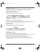
kombk.book Page 19 Tuesday, June 29, 1999 3:25 PM Installing the BayStack 450 Switch IP Configuration/Setup BootP Request Mode: [ BootP Disabled ] Configurable ------------------In-Band Stack IP Address: [ 0.0.0.0 ] In-Band Switch IP Address: [ 0.0.0.0 ] In-Band Subnet Mask: [ 0.0.0.0 ] In Use --------------0.0.0.0 Last BootP --------------0.0.0.0 0.0.0.0 0.0.0.0 Default Gateway: 0.0.0.0 0.0.0.0 [ 0.0.0.0 ] Use space bar to display choices, press or to select choice.
kombk.book Page 20 Tuesday, June 29, 1999 3:25 PM Using the BayStack 450 10/100/1000 Series Switch Stack Setup For the initial setup of a stack configuration, you need to enter the stack IP address, the subnet mask, and the gateway address (see Chapter 3, “Using the Console Interface,” for more information about configuring your BayStack 450 switch).
kombk.book Page 21 Tuesday, June 29, 1999 3:25 PM Installing the BayStack 450 Switch BayStack 450-24T Main Menu IP Configuration/Setup... SNMP Configuration... System Characteristics... Switch Configuration... Console/Comm Port Configuration... Display Hardware Units... Spanning Tree Configuration... TELNET Configuration... Software Download... Configuration File... Display Event Log Reset Reset to Default Settings Logout Use arrow keys to highlight option, press or to select option.
kombk.book Page 22 Tuesday, June 29, 1999 3:25 PM Using the BayStack 450 10/100/1000 Series Switch 4. Select IP Configuration/Setup (or press i) from the Main Menu. This selection displays the IP Configuration/Setup screen (Figure 2-17). Note: The IP interface of the BayStack 450 switch is only on VLAN 1. You can manage the switch only from VLAN 1 (or via routers that connect VLAN 1 to the network management station).
kombk.book Page 23 Tuesday, June 29, 1999 3:25 PM Installing the BayStack 450 Switch Note: IP addresses are written as four decimal numbers (for example, 123.123.123.123). Each decimal number represents an 8-bit octet. When strung together, the four octets form the 32-bit Internet address. This is called dotted-decimal notation. The largest possible value of a field in a dotted-decimal number is 255, which represents an octet of all ones. 6.
kombk.
kombk.book Page 1 Tuesday, June 29, 1999 3:25 PM Chapter 3 Using the Console Interface This chapter describes how to configure and manage the BayStack 450 switch using the menu-driven console interface (CI).
kombk.book Page 2 Tuesday, June 29, 1999 3:25 PM Using the BayStack 450 10/100/1000 Series Switch Using the CI Menus and Screens The CI menus and screens provide options that allow you to configure and manage the BayStack 450 switch. Help prompts at the bottom of each menu and screen explain how to enter data in the highlighted field and how to navigate the menus and screens. Some options allow you to toggle among several possible values; other options allow you to set or modify a parameter.
kombk.book Page 3 Tuesday, June 29, 1999 3:25 PM Using the Console Interface Screen Fields and Descriptions Figure 3-1 shows a map of the CI screens. The remainder of this chapter describes the CI screens and their fields, beginning with the main menu.
kombk.book Page 4 Tuesday, June 29, 1999 3:25 PM Using the BayStack 450 10/100/1000 Series Switch Main Menu This section describes the options available from the CI main menu (Figure 3-2). The CI screens and submenus for these options are described in the following sections. Note: Some menu options shown in this main menu example and in other screen examples in this chapter may not appear on your screen, depending on the switch options installed.
kombk.book Page 5 Tuesday, June 29, 1999 3:25 PM Using the Console Interface Table 3-1 describes the CI main menu options. Table 3-1. Console Interface Main Menu options Option Description IP Configuration/ Setup... Displays the IP Configuration/Setup screen (see “IP Configuration/Setup” on page 3-8). This screen allows you to set or modify IP configuration parameters. SNMP Configuration... Displays the SNMP Configuration screen (see “SNMP Configuration” on page 3-13).
kombk.book Page 6 Tuesday, June 29, 1999 3:25 PM Using the BayStack 450 10/100/1000 Series Switch Table 3-1. Console Interface Main Menu options (continued) Option Description Display Hardware Units Displays the Hardware Unit Information screen (see “Hardware Unit Information” on page 3-67). This screen lists the switch models, including any installed MDA and Cascade modules, that are configured in your standalone or stack configuration. Spanning Tree Configuration...
kombk.book Page 7 Tuesday, June 29, 1999 3:25 PM Using the Console Interface Table 3-1. Option Console Interface Main Menu options (continued) Description Caution: If you choose the Reset to Default Settings option, all of your configured settings will be replaced with factory default settings when you press [Enter].
kombk.book Page 8 Tuesday, June 29, 1999 3:25 PM Using the BayStack 450 10/100/1000 Series Switch IP Configuration/Setup The IP Configuration/Setup screen (Figure 3-3) allows you to set or modify the BayStack 450 switch IP configuration parameters. Data that you enter in the user-configurable fields takes effect as soon as you press [Enter]. Choose IP Configuration/Setup (or press i) from the main menu to open the IP Configuration/Setup screen.
kombk.book Page 9 Tuesday, June 29, 1999 3:25 PM Using the Console Interface Table 3-2. IP Configuration/Setup Screen Fields Field Description BootP Request Mode One of four modes of operation for BootP. (See “Choosing a BootP Request Mode” on page 3-10 for details about the four modes.) Default Value BootP Disabled Range BootP When Needed, BootP Always, BootP Disabled, BootP or Last Address Configurable Column header for the user-configurable fields in this screen.
kombk.book Page 10 Tuesday, June 29, 1999 3:25 PM Using the BayStack 450 10/100/1000 Series Switch Table 3-2. IP Configuration/Setup Screen Fields (continued) Field Description Default Gateway The IP address of the default gateway. Default Value 0.0.0.
kombk.book Page 11 Tuesday, June 29, 1999 3:25 PM Using the Console Interface • When the in-band IP address is not set from the console terminal, the switch broadcasts BootP requests until it receives a BootP reply containing an IP address. If the switch does not receive a BootP reply that contains an IP address, the switch cannot be managed in-band. If an IP address is not currently in use, these actions take effect immediately.
kombk.book Page 12 Tuesday, June 29, 1999 3:25 PM Using the BayStack 450 10/100/1000 Series Switch BootP or Last Address Allows the switch to be managed even if a BootP server is not reachable. When selected, this mode operates as follows: • When the IP data is entered from the console terminal, the data becomes the in-band address of the switch and BootP requests are not broadcast. The switch can be managed using this in-band IP address.
kombk.book Page 13 Tuesday, June 29, 1999 3:25 PM Using the Console Interface SNMP Configuration The SNMP Configuration screen (Figure 3-4) allows you to set or modify the SNMP configuration parameters. Choose SNMP Configuration (or press m) from the main menu to open the SNMP Configuration screen.
kombk.book Page 14 Tuesday, June 29, 1999 3:25 PM Using the BayStack 450 10/100/1000 Series Switch Table 3-3. SNMP Configuration Screen Fields (continued) Field Description Read-Write Community String The community string used for in-band read-write SNMP operations. Trap #1 IP Address 1 Community String Authentication Trap Link Up/Down Trap Default Value private Range Any ASCII string of up to 32 printable characters Number one of four trap IP addresses.
kombk.book Page 15 Tuesday, June 29, 1999 3:25 PM Using the Console Interface System Characteristics The System Characteristics screen (Figure 3-5) allows you to view system characteristics and contains three user-configurable fields: sysContact, sysName, and sysLocation. Choose System Characteristics (or press s) from the main menu to open the System Characteristics screen.
kombk.book Page 16 Tuesday, June 29, 1999 3:25 PM Using the BayStack 450 10/100/1000 Series Switch Table 3-4. System Characteristics Screen Fields Field Description Operation Mode Read-only field that indicates the operation mode of the unit, for example: • • When the unit is part of a stack configuration, the (read-only) field indicates the unit is operational in a stack, and lists the current unit number of this switch.
kombk.book Page 17 Tuesday, June 29, 1999 3:25 PM Using the Console Interface Table 3-4. System Characteristics Screen Fields (continued) Field Description sysObjectID A read-only field that provides a unique identification of the switch, which contains the vendor’s private enterprise number. sysUpTime A read-only field that shows the length of time since the last reset. Note that this field is updated when the screen is redisplayed.
kombk.book Page 18 Tuesday, June 29, 1999 3:25 PM Using the BayStack 450 10/100/1000 Series Switch Switch Configuration The Switch Configuration Menu screen (Figure 3-6) allows you to set or modify your switch configuration. Note: The High Speed Flow Control Configuration option only appears when an optional gigabit MDA is installed. Choose Switch Configuration (or press w) from the main menu to open the Switch Configuration Menu screen. Switch Configuration Menu MAC Address Table VLAN Configuration...
kombk.book Page 19 Tuesday, June 29, 1999 3:25 PM Using the Console Interface Table 3-5. Switch Configuration Menu Screen Options Option Description MAC Address Table Displays the MAC Address Table screen (see “MAC Address Table” on page 3-20). This screen allows you to view all MAC addresses and their associated port or trunk that the switch has learned, or to search for a particular MAC address (to see if the switch has learned the address). VLAN Configuration...
kombk.book Page 20 Tuesday, June 29, 1999 3:25 PM Using the BayStack 450 10/100/1000 Series Switch Table 3-5. Switch Configuration Menu Screen Options (continued) Option Description Display Port Statistics Displays the Port Statistics screen (see “Port Statistics” on page 3-54). This screen allows you to view detailed information about any switch port. Clear All Port Statistics Allows you to clear all port statistics.
kombk.book Page 21 Tuesday, June 29, 1999 3:25 PM Using the Console Interface MAC Address Table Aging Time: Find an Address: Port Mirroring Address A: Port Mirroring Address B: 00-60-FD-00-02-30 00-00-A2-85-BB-26 00-60-FD-12-02-15 00-08-C7-1D-4F-38 [ [ [ [ 300 seconds ] 00-00-00-00-00-00 ] 00-44-55-44-55-22 ] 00-33-44-33-22-44 ] Port: 1 Port: 1 Trunk:3 End of Address Table. Press Ctrl-P to see previous display. Press Ctrl-R to return to previous menu. Press Ctrl-C to return to Main Menu. Figure 3-7.
kombk.book Page 22 Tuesday, June 29, 1999 3:25 PM Using the BayStack 450 10/100/1000 Series Switch Table 3-6. MAC Address Table Screen Fields (continued) Field Description Port Mirroring Address A Only appears when you select any of the five address-based monitoring modes from the Port Mirroring Configuration screen. When you enter a MAC address in this field, it is also configured into the Port Mirroring Configuration screen.
kombk.book Page 23 Tuesday, June 29, 1999 3:25 PM Using the Console Interface VLAN Configuration Menu VLAN Configuration... VLAN Port Configuration... VLAN Display by Port... Traffic Class Configuration... Return to Switch Configuration Menu Use arrow keys to highlight option, press or to select option. Press Ctrl-R to return to previous menu. Press Ctrl-C to return to Main Menu. Figure 3-8.
kombk.book Page 24 Tuesday, June 29, 1999 3:25 PM Using the BayStack 450 10/100/1000 Series Switch VLAN Configuration The VLAN Configuration screen (Figure 3-9) allows you to assign standalone or stacked unit switch ports as VLAN port members. When you configure ports as VLAN port members, they become part of a set of ports that form a broadcast domain for a specific VLAN. You can assign switch ports, whether standalone or stacked unit ports, as VLAN port members of one or more VLANs.
kombk.book Page 25 Tuesday, June 29, 1999 3:25 PM Using the Console Interface Table 3-8 describes the VLAN Configuration screen fields. Table 3-8. VLAN Configuration Screen Fields Field Description Create VLAN Allows you to set up or view configured VLAN workgroups. Enter the number of the new VLAN you want to create or view, then press [Return]. The Port Membership fields indicate the corresponding VLAN workgroup configuration, if configured, or all dashes (-), indicating no VLAN Members configured.
kombk.book Page 26 Tuesday, June 29, 1999 3:25 PM Using the BayStack 450 10/100/1000 Series Switch Table 3-8. Field VLAN Configuration Screen Fields (continued) Description The Port Membership fields are displayed in six-port groups (for example, 1-6, 7-12, 13-18). The number of ports displayed depends on the switch model or type of optional MDA installed in the Uplink Module slot. Default U (All ports are assigned as untagged members of VLAN 1.
kombk.book Page 27 Tuesday, June 29, 1999 3:25 PM Using the Console Interface VLAN Port Configuration Unit: Port: Filter Tagged Frames: Filter Untagged Frames: Filter Unregistered Frames: Port Name: PVID: Port Priority: Tagging: [ 1 ] [ 12 ] [ No ] [ No ] [ No ] [ Unit 1, Port 12 ] [ 1 ] [ 0 ] [Untagged Access] Use space bar to display choices, press or to select choice. Press Ctrl-R to return to previous menu. Press Ctrl-C to return to Main Menu. Figure 3-10.
kombk.book Page 28 Tuesday, June 29, 1999 3:25 PM Using the BayStack 450 10/100/1000 Series Switch Table 3-9. VLAN Port Configuration Screen Fields (continued) Field Description Filter Untagged Frames Sets this port to filter (discard) all received untagged packets. Filter Unregistered Frames Port Name PVID Port Priority Tagging Default No Range No, Yes Sets this port to filter (discard) all received unregistered packets.
kombk.book Page 29 Tuesday, June 29, 1999 3:25 PM Using the Console Interface VLAN Display by Port The VLAN Display by Port screen (Figure 3-9) allows you to view VLAN characteristics associated with a specified switch port. Choose VLAN Display by Port (or press d) from the VLAN Configuration Menu screen to open the VLAN Display by Port screen.
kombk.book Page 30 Tuesday, June 29, 1999 3:25 PM Using the BayStack 450 10/100/1000 Series Switch Table 3-10 describes the VLAN Display by Port screen fields. Table 3-10. VLAN Display by Port Screen Fields Field Description Unit Allows you to select the unit number (when stacking is configured) to view. To view another unit, type its unit number and press [Enter], or press the spacebar to toggle the unit numbers. Port Allows you to select the number of the port you want to view.
kombk.book Page 31 Tuesday, June 29, 1999 3:25 PM Using the Console Interface Traffic Class Configuration User Priority ------------Priority 0: Priority 1: Priority 2: Priority 3: Priority 4: Priority 5: Priority 6: Priority 7: Traffic Class ------------[ Low ] [ Low ] [ Low ] [ Low ] [ Low ] [ Low ] [ Low ] [ Low ] Changing the priorities of the traffic classes will cause an automatic Reset to Current Settings to occur across the entire stack.
kombk.book Page 32 Tuesday, June 29, 1999 3:25 PM Using the BayStack 450 10/100/1000 Series Switch Port Configuration The Port Configuration screen (Figures 3-13 and 3-14) allows you to configure specific switch ports or all switch ports.
kombk.
kombk.book Page 34 Tuesday, June 29, 1999 3:25 PM Using the BayStack 450 10/100/1000 Series Switch Table 3-12. Port Configuration Screen Fields (continued) Field Description Port Indicates the switch port numbers that correspond to the field values in that row of the screen (for example, the field values in row 2 apply to switch port 2).
kombk.book Page 35 Tuesday, June 29, 1999 3:25 PM Using the Console Interface Choose High Speed Flow Control Configuration (or press h) from the Switch Configuration Menu screen to open the High Speed Flow Control Configuration screen. High Speed Flow Control Configuration Unit: [ 2 ] Autonegotiation: Flow Control: Preferred Phy: [ Enabled ] [ Disabled ] [ Right ] Active Phy: None Use space bar to display choices, press or to select choice. Press Ctrl-R to return to previous menu.
kombk.book Page 36 Tuesday, June 29, 1999 3:25 PM Using the BayStack 450 10/100/1000 Series Switch Table 3-13. High Speed Flow Control Configuration Screen Fields (continued) Field Description Autonegotiation When enabled, the port only advertises support for 1000 Mb/s operation, in full-duplex mode. Flow Control Default Value Enabled Range Enabled, Disabled Allows you to control traffic and avoid congestion on the gigabit MDA port.
kombk.book Page 37 Tuesday, June 29, 1999 3:25 PM Using the Console Interface When a pause frame is received (by either the gigabit MDA port or its link partner), the port suspends transmission of frames for a number of slot times specified in the control frame or until a pause-release control frame is received. Both devices on the link must support this mode when it is selected. Asymmetric This mode allows the link partner to send flow control pause frames to the gigabit MDA port.
kombk.book Page 38 Tuesday, June 29, 1999 3:25 PM Using the BayStack 450 10/100/1000 Series Switch MultiLink Trunk Configuration Menu MultiLink Trunk Configuration... MultiLink Trunk Utilization... Return to Switch Configuration Menu Use arrow keys to highlight option, press or to select option. Press Ctrl-R to return to previous menu. Press Ctrl-C to return to Main Menu. Figure 3-16.
kombk.book Page 39 Tuesday, June 29, 1999 3:25 PM Using the Console Interface MultiLink Trunk Configuration Screen The MultiLink Trunk Configuration screen (Figure 3-17) allows you to configure up to six trunks in a standalone switch or stack. In a stack configuration, trunk members can be distributed between any of the units within the same stack configuration.
kombk.
kombk.book Page 41 Tuesday, June 29, 1999 3:25 PM Using the Console Interface Table 3-15. MultiLink Trunk Configuration Screen Fields (continued) Field Description STP Learning The STP Learning column contains a single field for each row that, when enabled, allows the specified trunk to participate in the spanning tree. This setting overrides those of the individual trunk members. Fast is the same as Normal, except that the state transition timer is shortened to two seconds.
kombk.book Page 42 Tuesday, June 29, 1999 3:25 PM Using the BayStack 450 10/100/1000 Series Switch MultiLink Trunk Utilization Trunk ----1 Traffic Type ------------[ Rx and Tx ] Unit/Port --------3/6 3/7 3/9 3/17 4/25 4/26 2 [ Rx and Tx ] 3 [ Rx and Tx ] 6/13 6/14 4 [ Rx and Tx ] 5/19 5/20 Last 5 Minutes -------------90.0% 20.0% 35.0% 85.0% 45.0% 25.0% Last 30 Minutes --------------70.0% 55.0% 45.0% 35.0% 45.0% 70.0% Last Hour --------90.0% 80.0% 45.0% 20.0% 50.0% 35.0% 35.0% 30.0% 35.
kombk.book Page 43 Tuesday, June 29, 1999 3:25 PM Using the Console Interface MultiLink Trunk Utilization Trunk ----5 6 Traffic Type ------------[ Rx and Tx ] [ [ [ [ Rx Rx Rx Rx and and and and Tx Tx Tx Tx Unit/Port --------8/22 8/23 ] ] ] ] Last 5 Minutes -------------45.0% 55.0% 3/2 1/2 7/2 5/6 65.0% 45.0% 25.0% 75.0% Last 30 Minutes --------------35.0% 25.0% Last Hour --------50.0% 70.0% 30.0% 50.0% 40.0% 80.0% 55.0% 35.0% 50.0% 55.0% Press Ctrl-P to display utilization for trunks 1-4.
kombk.book Page 44 Tuesday, June 29, 1999 3:25 PM Using the BayStack 450 10/100/1000 Series Switch Table 3-16. MultiLink Trunk Utilization Screen Fields (continued) Field Description Last 5 Minutes This read-only field indicates the percentage of packets (of the type specified in the Traffic Type field) utilized by the port in the last 5 minutes. This field provides a running average of network activity and is updated every 15 seconds.
kombk.book Page 45 Tuesday, June 29, 1999 3:25 PM Using the Console Interface Port Mirroring Configuration The Port Mirroring Configuration screen allows you to configure a specific switch port to monitor up to two specified ports or two MAC addresses. You can specify port-based monitoring or address-based monitoring. In a stack configuration, you can monitor ports that reside on different units within the stack.
kombk.book Page 46 Tuesday, June 29, 1999 3:25 PM Using the BayStack 450 10/100/1000 Series Switch Table 3-17 describes the Port Mirroring Configuration screen fields. Table 3-17. Port Mirroring Configuration Screen Fields Field Description Monitoring Mode Allows a user to select any one of six port-based monitoring modes or any one of five address-based monitoring modes (see Table 3-18).
kombk.book Page 47 Tuesday, June 29, 1999 3:25 PM Using the Console Interface Table 3-17. Port Mirroring Configuration Screen Fields (continued) Field Description Address B Indicates the MAC addresses that will be monitored by the designated port monitor when one of the address-based monitoring modes is selected. This port will be monitored according to the value of Address B in the selected Monitoring Mode field (see Table 3-18).
kombk.book Page 48 Tuesday, June 29, 1999 3:25 PM Using the BayStack 450 10/100/1000 Series Switch Rate Limiting Configuration The Rate Limiting Configuration screen allows you to limit the forwarding rate of broadcast and multicast packets. Figures 3-21 and 3-22 show sample rate-limiting values for the two Rate Limiting Configuration screens. Note: If a port is configured for rate-limiting, and it is a MultiLink trunk member, all trunk member ports implement rate-limiting.
kombk.book Page 49 Tuesday, June 29, 1999 3:25 PM Using the Console Interface Port Packet Type ---------------15 [ Both ] 16 [ Both ] 17 [ Multicast ] 18 [ Both ] 19 [ Both ] 20 [ Both ] 21 [ Broadcast ] 22 [ Both ] 23 [ Both ] 24 [ Multicast ] 25 [ Both ] 26 [ Both ] 27 [ Both ] 28 [ Both ] Switch[ Both ] Stack [ Both ] Rate Limiting Configuration Unit: [ 1 ] Limit Last 5 Minutes Last Hour ----------------------------[ None ] 44.0% 56.0% [ None ] 67.0% 34.0% [ 10% ] 65.0% 48.0% [ None ] 77.0% 74.
kombk.book Page 50 Tuesday, June 29, 1999 3:25 PM Using the BayStack 450 10/100/1000 Series Switch Table 3-19 describes the Rate Limiting Configuration screen fields. Table 3-19. Rate Limiting Configuration Screen Fields Field Description Unit Only appears if the switch is participating in a stack configuration. The field allows you to select the number of the unit you want to view or configure.
kombk.book Page 51 Tuesday, June 29, 1999 3:25 PM Using the Console Interface IGMP Configuration The IGMP Configuration screen allows you to set your switch ports to optimize IP multicast packets in a bridged Ethernet environment (see “IGMP Snooping” on page 1-48). Figure 3-23 shows an example of the IGMP Configuration screen in a stacked configuration. When installed as a standalone switch, the screen does not display the Unit # field designation.
kombk.book Page 52 Tuesday, June 29, 1999 3:25 PM Using the BayStack 450 10/100/1000 Series Switch Table 3-20 describes the IGMP Configuration screen fields. Table 3-20. IGMP Configuration Screen Fields Field Description VLAN Allows you to set up or view IGMP VLAN configurations on specified VLANs. You can use the space bar to toggle to any existing IGMP VLAN configurations (the maximum number of VLANs that can be displayed is 64).
kombk.book Page 53 Tuesday, June 29, 1999 3:25 PM Using the Console Interface Table 3-20. IGMP Configuration Screen Fields (continued) Field Description Query Time Allows a user to control the number of IGMP messages allowed on the subnet by varying the Query Interval (the Query Interval is the interval between general queries sent by the multicast router).
kombk.book Page 54 Tuesday, June 29, 1999 3:25 PM Using the BayStack 450 10/100/1000 Series Switch Port Statistics The Port Statistics screen (Figure 3-24) allows you to view detailed information about any switch port in a stacked or standalone configuration. The screen is divided into two sections (Received and Transmitted) so that you can compare and evaluate throughput or other port parameters. All screen data is updated approximately every 2 seconds.
kombk.book Page 55 Tuesday, June 29, 1999 3:25 PM Using the Console Interface Table 3-21 describes the Port Statistics screen fields. Note: In a stacked configuration, the Port Statistics screen appears in a slightly different format when the port selected in the Unit/Port field is configured with a gigabit MDA. Table 3-21. Port Statistics Screen Fields Field Description Unit Only appears if the switch is participating in a stack configuration.
kombk.book Page 56 Tuesday, June 29, 1999 3:25 PM Using the BayStack 450 10/100/1000 Series Switch Table 3-21. Port Statistics Screen Fields (continued) Field Description Packets 64 bytes Received column: Indicates the total number of 64-byte packets received on this port. Transmitted column: Indicates the total number of 64-byte packets transmitted successfully on this port. 65-127 bytes Received column: Indicates the total number of 65-byte to 127-byte packets received on this port.
kombk.book Page 57 Tuesday, June 29, 1999 3:25 PM Using the Console Interface Table 3-21. Port Statistics Screen Fields (continued) Field Description Collisions Indicates the total number of collisions detected on this port. Single Collisions Indicates the total number of packets that were transmitted successfully on this port after a single collision. Multiple Collisions Indicates the total number of packets that were transmitted successfully on this port after more than one collision.
kombk.book Page 58 Tuesday, June 29, 1999 3:25 PM Using the BayStack 450 10/100/1000 Series Switch Console/Comm Port Configuration The Console/Comm Port Configuration screen (Figure 3-25) allows you to configure and modify the console/comm port parameters of a standalone switch or any participating switch in a stack configuration. Choose Console/Comm Port Configuration (or press o) from the main menu to open the Console/Comm Port Configuration screen.
kombk.book Page 59 Tuesday, June 29, 1999 3:25 PM Using the Console Interface Table 3-22. Console/Comm Port Configuration Screen Fields (continued) Field Description Comm Port Stop Bits A read-only field that indicates the current console/comm port stop bit setting. Console Port Speed Allows you to set the console/comm port baud rate to match the baud rate of the console terminal.
kombk.book Page 60 Tuesday, June 29, 1999 3:25 PM Using the BayStack 450 10/100/1000 Series Switch Table 3-22. Console/Comm Port Configuration Screen Fields (continued) Field Description Console Switch Password Enables password protection for accessing the console interface (CI) of a standalone switch through a TELNET session, a console terminal, or both. If you set this field to Required, you can use the Logout option to restrict access to the CI.
kombk.book Page 61 Tuesday, June 29, 1999 3:25 PM Using the Console Interface Table 3-22. Console/Comm Port Configuration Screen Fields (continued) Field Description Console Read-Write Switch Password When the Console Switch Password field is set to Required (for TELNET, for Console, or for Both), this field allows read-write password access to the CI of a standalone switch. Users can log in to the CI using the correct password (see default), and can change any parameter, except the stack passwords.
kombk.book Page 62 Tuesday, June 29, 1999 3:25 PM Using the BayStack 450 10/100/1000 Series Switch Table 3-22. Console/Comm Port Configuration Screen Fields (continued) Field Description Precaución: Si modifica las contraseñas predeterminadas asignadas por el sistema, asegúrese de anotar las nuevas contraseñas y guárdelas en un lugar seguro. Si olvida las nuevas contraseñas, no podrá acceder al interfaz de la consola. En ese caso, póngase en contacto con Nortel Networks para obtener ayuda al respecto.
kombk.book Page 63 Tuesday, June 29, 1999 3:25 PM Using the Console Interface Table 3-22. Console/Comm Port Configuration Screen Fields (continued) Field Description Console Read-Write Stack Password When the Console Switch Password field is set to Required (for TELNET, for Console, or for Both), this field allows read-write password access to the CI of any participating switch in a stack configuration.
kombk.book Page 64 Tuesday, June 29, 1999 3:25 PM Using the BayStack 450 10/100/1000 Series Switch Table 3-22. Field Console/Comm Port Configuration Screen Fields (continued) Description Precaución: Si modifica las contraseñas predeterminadas asignadas por el sistema, asegúrese de anotar las nuevas contraseñas y guárdelas en un lugar seguro. Si olvida las nuevas contraseñas, no podrá acceder al interfaz de la consola. En ese caso, póngase en contacto con Nortel Networks para obtener ayuda al respecto.
kombk.book Page 65 Tuesday, June 29, 1999 3:25 PM Using the Console Interface Renumber Stack Units The Renumber Stack Units screen (Figure 3-26) allows you to renumber the units configured in the stack. When selected, this option identifies the unit number of each unit in the stack configuration by lighting the corresponding number of (100 Mb/s port) LEDs on each unit for approximately 10 seconds. For example, unit 3 will display three LEDs.
kombk.book Page 66 Tuesday, June 29, 1999 3:25 PM Using the BayStack 450 10/100/1000 Series Switch Table 3-23 describes the Renumber Stack Units screen options: Table 3-23. Renumber Stack Units Screen Options Option Description Current Unit Number Read-only fields listing the current unit number of each of the configured stack units.
kombk.book Page 67 Tuesday, June 29, 1999 3:25 PM Using the Console Interface Hardware Unit Information The Hardware Unit Information screen (Figure 3-27) lists the switch models, including any installed MDA and Cascade modules, that are configured in your standalone or stack configuration. Choose Display Hardware Units (or press h) from the main menu to open the Hardware Unit Information screen.
kombk.book Page 68 Tuesday, June 29, 1999 3:25 PM Using the BayStack 450 10/100/1000 Series Switch Choose Spanning Tree Configuration (or press p) from the main menu to open the Spanning Tree Configuration Menu screen. Spanning Tree Configuration Menu Spanning Tree Port Configuration... Display Spanning Tree Switch Settings Return to Main Menu Use arrow keys to highlight option, press or to select option. Press Ctrl-R to return to previous menu. Press Ctrl-C to return to Main Menu.
kombk.book Page 69 Tuesday, June 29, 1999 3:25 PM Using the Console Interface Spanning Tree Port Configuration The Spanning Tree Port Configuration screen allows you to configure individual switch ports or all switch ports for participation in the spanning tree. Note: If spanning tree participation of any trunk member is changed (enabled or disabled), the spanning tree participation of all members of that trunk is changed similarly.
kombk.
kombk.book Page 71 Tuesday, June 29, 1999 3:25 PM Using the Console Interface Table 3-25. Spanning Tree Port Configuration Screen Fields (continued) Field Description Participation Allows you to configure any (or all) of the switch ports for Spanning tree participation. When an individual port is a trunk member (see Trunk field), changing this setting for one of the trunk members changes the setting for all members of that trunk.
kombk.book Page 72 Tuesday, June 29, 1999 3:25 PM Using the BayStack 450 10/100/1000 Series Switch Display Spanning Tree Switch Settings The Spanning Tree Switch Settings screen (Figure 3-31) allows you to view spanning tree parameter values for the BayStack 450 switch. Choose Display Spanning Tree Switch Settings (or press d) from the Spanning Tree Configuration Menu screen to open the Spanning Tree Switch Settings screen.
kombk.book Page 73 Tuesday, June 29, 1999 3:25 PM Using the Console Interface Table 3-26 describes the Spanning Tree Switch Settings parameters. Table 3-26. Spanning Tree Switch Settings Parameters Parameter Description Bridge Priority Indicates the management-assigned priority value of the bridge ID in hexadecimal notation, which is the most significant byte of the bridge ID. The STA uses this parameter to determine the root bridge (or designated bridge).
kombk.book Page 74 Tuesday, June 29, 1999 3:25 PM Using the BayStack 450 10/100/1000 Series Switch Table 3-26. Spanning Tree Switch Settings Parameters (continued) Parameter Description Forward Delay Indicates the Forward Delay parameter value that the root bridge is currently using. This value specifies the amount of time that the bridge ports remain in the Listening and Learning states before entering the Forwarding state.
kombk.book Page 75 Tuesday, June 29, 1999 3:25 PM Using the Console Interface TELNET Configuration The TELNET Configuration screen (Figure 3-32) allows a user at a remote console terminal to communicate with the BayStack 450 switch as if the console terminal were directly connected to it. You can have up to four active TELNET sessions at one time. Choose TELNET Configuration (or press t) from the main menu to open the TELNET Configuration screen.
kombk.book Page 76 Tuesday, June 29, 1999 3:25 PM Using the BayStack 450 10/100/1000 Series Switch Table 3-27. Field TELNET Configuration Screen Fields Description TELNET Access Allows a user remote access to the CI through a TELNET session. Login Timeout Login Retries Inactivity Timeout Event Logging Default Value: Enabled Range: Enabled, Disabled Specifies the amount of time a user has to enter the correct password at the console-terminal prompt.
kombk.book Page 77 Tuesday, June 29, 1999 3:25 PM Using the Console Interface Table 3-27. Field TELNET Configuration Screen Fields (continued) Description Allowed Source Specifies up to 10 user-assigned host IP addresses that are allowed TELNET access to the CI. IP Address Default Value: 0.0.0.
kombk.book Page 78 Tuesday, June 29, 1999 3:25 PM Using the BayStack 450 10/100/1000 Series Switch Software Download Caution: Do not interrupt power to the device during the software download process. If the power is interrupted, the firmware image can become corrupted. Achtung: Unterbrechen Sie die Stromzufuhr zum Gerät nicht, während die Software heruntergeladen wird. Bei Unterbrechung der Stromzufuhr kann das Firmware-Image beschädigt werden.
kombk.book Page 79 Tuesday, June 29, 1999 3:25 PM Using the Console Interface You can monitor the software download process by observing the BayStack 450 switch LEDs (see “LED Indications During the Download Process” on page 3-80). Software Download Image Filename: TFTP Server IP Address: [ b4501102.img ] [ 192.0.1.12 ] Start TFTP Load of New Image: [ Yes ] The Software Download process has started. Do NOT power down the switch before the process has completed (approximately 10 minutes).
kombk.book Page 80 Tuesday, June 29, 1999 3:25 PM Using the BayStack 450 10/100/1000 Series Switch Table 3-28. Software Download Screen Fields (continued) Field Description TFTP Server IP Address The IP address of your TFTP load host. Default Value 0.0.0.
kombk.book Page 81 Tuesday, June 29, 1999 3:25 PM Using the Console Interface Note: The LED indications described in Table 3-29 apply to a 24-port switch model. Although a 12-port switch provides similar LED indications, the LED indication sequence is associated within the 12-port range. Table 3-29. LED Indications During the Software Download Process Phase Description LED Indications 1 The switch downloads the new software image.
kombk.book Page 82 Tuesday, June 29, 1999 3:25 PM Using the BayStack 450 10/100/1000 Series Switch Configuration File The Configuration File Download/Upload screen (Figure 3-34) allows you to store your switch/stack configuration parameters on a TFTP server. You can retrieve the configuration parameters of a standalone switch or an entire stack and use the retrieved parameters to automatically configure a replacement switch or stack.
kombk.book Page 83 Tuesday, June 29, 1999 3:25 PM Using the Console Interface Table 3-30. Configuration File Download/Upload Screen Fields Field Description Configuration Image Filename The file name you have chosen for the configuration file. Choose a meaningful file name that will allow you to identify the file for retrieval when required. The file must already exist on your TFTP server and must be read/write enabled.
kombk.book Page 84 Tuesday, June 29, 1999 3:25 PM Using the BayStack 450 10/100/1000 Series Switch • A configuration file obtained from a standalone switch can only be used to configure other standalone switches that have the same firmware revision and model type as the donor standalone switch.
kombk.book Page 85 Tuesday, June 29, 1999 3:25 PM Using the Console Interface Display Event Log This section describes the various functions of the Event Log screen (Figure 3-35). When the switch is part of a stack configuration, the Event Log screen displays only the data for the specific unit you are connected to through the Console/ Comm port. However, if you are connected to a stack unit through a TELNET session, the Event Log screen displays the data for the base unit of that stack configuration.
kombk.book Page 86 Tuesday, June 29, 1999 3:25 PM Using the BayStack 450 10/100/1000 Series Switch The Event Log screen provides the following information: • Software download: Indicates the new software version. • Authentication failure: Indicates any attempted SNMP get or set access that specified an invalid community string. • TELNET session status: Indicates various TELNET events. (For details on configuring this feature, see “TELNET Configuration” on page 3-75.
kombk.book Page 87 Tuesday, June 29, 1999 3:25 PM Using the Console Interface Figure 3-37 shows an example of the event log entry for this type of event. Entry Number: 3 sysUpTime: 02:29:44 Reset Count: 2 The last event exceeded the write threshold. Further write attempts by this event are blocked. The write threshold will be cleared when the switch is reset or when the Event Log is compressed. Figure 3-37.
kombk.book Page 88 Tuesday, June 29, 1999 3:25 PM Using the BayStack 450 10/100/1000 Series Switch Reset The Reset option (accessed from the main menu) allows you to reset a standalone switch, a specific unit in a stack configuration, or an entire stack without erasing any configured switch parameters. Resetting the switch takes approximately 5 seconds. During this time, the switch initiates a self-test that comprises various diagnostic routines and subtests.
kombk.book Page 89 Tuesday, June 29, 1999 3:25 PM Using the Console Interface *********************************************** * Nortel Networks * * Copyright (c) 1996,1999 * * All Rights Reserved * * BayStack 450- xxx * * Versions: HW:Rev x FW:V x.xx SW:v x.x.x.x * *********************************************** Enter Ctrl-Y to begin. Figure 3-40.
kombk.book Page 90 Tuesday, June 29, 1999 3:25 PM Using the BayStack 450 10/100/1000 Series Switch Reset to Default Settings Caution: If you choose the Reset to Default Settings command, all of your configured settings will be replaced with factory default settings when you press [Enter]. Achtung: Bei Auswahl des Befehls zur Rücksetzung auf die Standardeinstellungen werden alle von Ihnen konfigurierten Einstellungen durch die werkseitigen Standardeinstellungen ersetzt, wenn Sie die Eingabetaste drücken.
kombk.book Page 91 Tuesday, June 29, 1999 3:25 PM Using the Console Interface The results of the self-test are displayed briefly (5 or 10 seconds) in the Self-Test screen (Figure 3-41), which is followed by the Nortel Networks logo screen (Figure 3-42). BayStack 450-24T Self-Test CPU RAM test ASIC addressing test ASIC buffer RAM test Port internal loopback test Fan Test ... ... ... ... Pass Pass Pass Pass .Pass Self-test complete. Figure 3-41.
kombk.book Page 92 Tuesday, June 29, 1999 3:25 PM Using the BayStack 450 10/100/1000 Series Switch *********************************************** * Nortel Networks * * Copyright (c) 1996,1999 * * All Rights Reserved * * BayStack 450- xxx * * Versions: HW:Rev x FW:V x.xx SW:v x.x.x.x * *********************************************** Enter Ctrl-Y to begin. Figure 3-42.
kombk.book Page 93 Tuesday, June 29, 1999 3:25 PM Using the Console Interface Logout The Logout option (accessed from the main menu) allows a user working at a password-protected console terminal or in an active TELNET session to terminate the session. The Logout option works as follows: • If the user is accessing the BayStack 450 switch through a TELNET session, the Logout option terminates the TELNET session.
kombk.
kombk.book Page 1 Tuesday, June 29, 1999 3:25 PM Chapter 4 Troubleshooting This chapter describes how to isolate and diagnose problems with your BayStack 450 switch. This chapter covers the following topics: • Interpreting the LEDs • Diagnosing and correcting the problem -- Normal power-up sequence -- Port connection problems The chapter topics lead you through a logical process for troubleshooting the BayStack 450 switch.
kombk.book Page 2 Tuesday, June 29, 1999 3:25 PM Using the BayStack 450 10/100/1000 Series Switch Interpreting the LEDs Figure 4-1 shows the BayStack 450-24T and BayStack 450-12T LED display panels. Figure 4-2 shows the BayStack 450-12F LED display panel. Table 4-1 describes the LEDs.
kombk.book Page 3 Tuesday, June 29, 1999 3:25 PM Troubleshooting BayStack 450-12F Switch Pwr Cas Up 1 2 4 3 5 6 7 8 9 10 11 12 Link Status Dwn F Dx RPSU Base Activity BayStack 450-12F = Dual color LED BS45071A Figure 4-2. Table 4-1. BayStack 450-12F LED Display Panel BayStack 450 Switch LED Descriptions Label Type Color State Meaning Pwr Power status Green On DC power is available to the switch’s internal circuitry. Off No AC power to switch or power supply failed.
kombk.book Page 4 Tuesday, June 29, 1999 3:25 PM Using the BayStack 450 10/100/1000 Series Switch Table 4-1. Label BayStack 450 Switch LED Descriptions (continued) Type Color State Meaning Amber or Green Blinking Incompatible software revision or unable to obtain a unit ID (Renumber Stack Unit table full). The unit is on the ring but cannot participate in the stack configuration. Off The switch is in standalone mode.
kombk.book Page 5 Tuesday, June 29, 1999 3:25 PM Troubleshooting Table 4-1. BayStack 450 Switch LED Descriptions (continued) Label Type Color State Meaning 10/100 10/100 Mb/s port speed indicator Green On The corresponding port is set to operate at 100 Mb/s and the link is good. Green Blinking The corresponding port has been disabled by software. Amber On The corresponding port is set to operate at 10 Mb/s and the link is good.
kombk.book Page 6 Tuesday, June 29, 1999 3:25 PM Using the BayStack 450 10/100/1000 Series Switch Avertissement: Pour éviter tout risque d'électrocution, ne jamais retirer le capot de l'appareil. Cet appareil ne contient aucune pièce accessible par l'utilisateur. Advertencia: A fin de evitar daños personales por corrientes eléctricas peligrosas, no desmonte nunca la cubierta superior de este dispositivo. Los componentes internos no son reparables por el usuario.
kombk.book Page 7 Tuesday, June 29, 1999 3:25 PM Troubleshooting Table 4-2. Corrective Actions Symptom Probable cause Corrective action All LEDs are off. The switch is not receiving AC Verify that the AC power cord is fastened securely power. at both ends and that power is available at the AC power outlet. The fans are not operating or Verify that there is sufficient space for adequate the airflow is blocked, causing airflow on both sides of the switch. the unit to overheat.
kombk.book Page 8 Tuesday, June 29, 1999 3:25 PM Using the BayStack 450 10/100/1000 Series Switch Autonegotiation Modes Port connection problems can occur when a port (or station) is connected to another port (or station) that is not operating in a compatible mode (for example, connecting a full-duplex port on one station to a half-duplex port on another station). The BayStack 450 switch negotiates port speeds according to the IEEE 802.3u autonegotiating standard.
kombk.
kombk.
kombk.book Page 1 Tuesday, June 29, 1999 3:25 PM Appendix A Technical Specifications This appendix lists the technical specifications for the BayStack 450 10/100/1000 Series Switches.
kombk.book Page 2 Tuesday, June 29, 1999 3:25 PM Using the BayStack 450 10/100/1000 Series Switch Physical Dimensions Parameter Specifications Height 7.03 cm (2.77 in.) Width 44.07 cm (17.55 in.) Depth 38.1 cm (15.0 in) Weight 5.26 kg (11.
kombk.book Page 3 Tuesday, June 29, 1999 3:25 PM Technical Specifications Interface Options • 10BASE-T/100BASE-TX -- RJ-45 (8-pin modular) connectors for MDI-X interface • 100BASE-FX Fiber -- SC and MT-RJ connectors for switched 100 Mb/s (100BASE-FX) connections over 50/125 and 62.
kombk.book Page 4 Tuesday, June 29, 1999 3:25 PM Using the BayStack 450 10/100/1000 Series Switch Declaration of Conformity The Declaration of Conformity for the BayStack 450 switches complies with ISO/ IEC Guide 22 and EN45014. The declaration identifies the product models, the Nortel Networks name and address, and the specifications recognized by the European community.
kombk.book Page 1 Tuesday, June 29, 1999 3:25 PM Appendix B Gigabit Fiber Optical Characteristics The Uplink/Expansion Module on the BayStack 450 switch supports 1000BASE-X (Gigabit Ethernet) MDAs. This appendix describes the optical characteristics of the 1000BASE-X MDAs. See Appendix C, “Media Dependent Adapters,” for more information about MDAs. 1000BASE-SX Models The 450-1SX and 450-1SR MDAs provide 1000BASE-SX (850 nanometers, short wavelength, Gigabit Ethernet) connectivity.
kombk.book Page 2 Tuesday, June 29, 1999 3:25 PM Using the BayStack 450 10/100/1000 Series Switch Transmit Characteristics Table B-2 lists the transmit characteristics for the 1000BASE-SX models: Table B-2. 1000BASE-SX Transmit Characteristics Description 62.5 Micron Multimode Fiber 50 Micron Multimode Fiber Transmitter type Shortwave Laser Shortwave Laser Signaling speed 1.25 ± 100 ppm 1.
kombk.book Page 3 Tuesday, June 29, 1999 3:25 PM Gigabit Fiber Optical Characteristics Receive Characteristics Table B-3 lists the receive characteristics for the 1000BASE-SX models: Table B-3. 1000BASE-SX Receive Characteristics Description 62.5 Micron Multimode Fiber 50 Micron Multimode Fiber Units Signaling Speed (range) 1.25 ± 100 ppm 1.
kombk.book Page 4 Tuesday, June 29, 1999 3:25 PM Using the BayStack 450 10/100/1000 Series Switch Table B-4. Worst-Case 1000BASE-SX Power Budget and Penalties 62.5 Micron Multimode Fiber 50 Micron Multimode Fiber Units Modal bandwidth as measured at 850 nm (minimum, overfilled launch) 160 200 400 500 MHz · km Link power budget 7.5 7.5 7.5 7.5 dB Operating distance 220 275 500 550 m Channel insertion loss 1, 2 2.38 2.60 3.37 3.56 dB Link power penalties 4.27 4.29 4.07 3.
kombk.book Page 5 Tuesday, June 29, 1999 3:25 PM Gigabit Fiber Optical Characteristics Transmit Characteristics Table B-6 lists the transmit characteristics for the 1000BASE-LX models: Table B-6. 1000BASE-LX Transmit Characteristics Description 62.5 Micron Multimode Fiber 50 Micron Multimode Fiber 10 Micron Single-Mode Fiber Transmitter type Longwave Laser Longwave Laser Longwave Laser Signaling speed (range) 1.25 ± 100 ppm 1.25 ± 100 ppm 1.
kombk.book Page 6 Tuesday, June 29, 1999 3:25 PM Using the BayStack 450 10/100/1000 Series Switch Table B-7. 1000BASE-LX Receive Characteristics (continued) Description Value Units Receive sensitivity – 19 dBm 12 dB Stressed receive sensitivity , – 14.4 dBm Receive electrical 3 dB upper cutoff frequency (maximum) 1500 MHz Vertical eye-closure penalty 2.60 Return loss (minimum) 1 2 3 dB 1 Measured with conformance test signal at TP3 (see IEEE 802.3, Clause 38.6.
kombk.book Page 1 Tuesday, June 29, 1999 3:25 PM Appendix C Media Dependent Adapters This appendix describes the optional media dependent adapters (MDAs) that are available from Nortel Networks. The MDAs can support high-speed connections to servers, shared Fast Ethernet hubs, or backbone devices. Note: The MDAs are not hot-swappable. Power down the switch before installing or removing an MDA.
kombk.book Page 2 Tuesday, June 29, 1999 3:25 PM Using the BayStack 450 10/100/1000 Series Switch 10BASE-T/100BASE-TX MDA The 400-4TX MDA (Figure C-1) uses four 10BASE-T/100BASE-TX RJ-45 (8-pin modular) port connectors to attach Ethernet devices. Table C-1 describes the 400-4TX MDA components and LEDs. 1 2 100 10 F Dx Activity 400-4TX MDA 5 4 3 BS45042A Figure C-1. Table C-1.
kombk.book Page 3 Tuesday, June 29, 1999 3:25 PM Media Dependent Adapters The RJ-45 ports are configured as media-dependent interface-crossover (MDI-X) connectors. These ports connect over straight cables to the network interface controller (NIC) card in a node or server, similar to a conventional Ethernet repeater hub. If you are connecting to another Ethernet hub or Ethernet switch, you need a crossover cable unless an MDI connection exists on the associated port of the attached device.
kombk.book Page 4 Tuesday, June 29, 1999 3:25 PM Using the BayStack 450 10/100/1000 Series Switch There are two 100BASE-FX models (Figure C-2): • 400-2FX MDA The 400-2FX MDA uses two longwave 1300 nm SC connectors to attach devices over 62.5/125 or 50/125 micron multimode fiber optic cable. • 400-4FX MDA The 400-4FX MDA uses four longwave 1300 nm MT-RJ connectors to attach devices over 62.5/125 or 50/125 micron multimode fiber optic cable.
kombk.book Page 5 Tuesday, June 29, 1999 3:25 PM Media Dependent Adapters For installation instructions, see “Installing an MDA” on page C-11. Table C-2. 100BASE-FX MDA Components Item Label Description 1 Link Communications link LEDs (green): On: Valid communications link established. Off: The communications link connection is bad or there is no connection to this port. Blinking: The corresponding port is management disabled.
kombk.book Page 6 Tuesday, June 29, 1999 3:25 PM Using the BayStack 450 10/100/1000 Series Switch 1000BASE-SX MDAs Warning: This is a Class 1 Laser/LED product. It contains a laser light source that can injure your eyes. Never look into an optical fiber or connector port. Always assume that the fiber optic cable or connector is connected to a laser light source. Vorsicht: Dieses Laser/LED-Produkt der Klasse 1 enthält eine Laserlichtquelle, die zu Augenverletzungen führen kann.
kombk.book Page 7 Tuesday, June 29, 1999 3:25 PM Media Dependent Adapters There are two 1000BASE-SX (shortwave gigabit) MDA models (Figure C-3): • The 450-1SR MDA is a single MAC MDA with a separate redundant Phy (backup Phy port). Only one Phy port can be active at any time. If the active Phy port fails, the redundant Phy port automatically becomes the active port. • The 450-1SX MDA is a single PHY MDA. Both models conform to the IEEE 802.
kombk.book Page 8 Tuesday, June 29, 1999 3:25 PM Using the BayStack 450 10/100/1000 Series Switch Table C-3. 1000BASE-SX MDA Components Item Label Description 1 Link Communication link LEDs (green): On: Valid communications link. Off: The communications link connection is bad or there is no connection to this port. Blinking: The corresponding port is management disabled. 2 PHY (or) Phy Select Phy status LEDs (green): On: The corresponding Phy port is active.
kombk.book Page 9 Tuesday, June 29, 1999 3:25 PM Media Dependent Adapters M1000BASE-LX MDAs Warning: This is a Class 1 Laser/LED product. It contains a laser light source that can injure your eyes. Never look into an optical fiber or connector port. Always assume that the fiber optic cable or connector is connected to a laser light source. Vorsicht: Dieses Laser/LED-Produkt der Klasse 1 enthält eine Laserlichtquelle, die zu Augenverletzungen führen kann.
kombk.book Page 10 Tuesday, June 29, 1999 3:25 PM Using the BayStack 450 10/100/1000 Series Switch There are two 1000BASE-LX (longwave gigabit) MDA models (Figure C-4): • The 450-1LR MDA is a single MAC MDA with a separate redundant Phy (backup Phy port). Only one Phy port can be active at any time. If the active Phy port fails, the redundant Phy port automatically becomes the active port. • The 450-1LX MDA is a single Phy MDA. Both models conform to the IEEE 802.
kombk.book Page 11 Tuesday, June 29, 1999 3:25 PM Media Dependent Adapters For installation instructions, see “Installing an MDA” on page C-11. Table C-4. 1000BASE-LX MDA Components Item Label Description 1 Link Communication link LEDs (green): On: Valid communications link. Off: The communications link connection is bad or there is no connection to this port. Blinking: The corresponding port is management disabled.
kombk.book Page 12 Tuesday, June 29, 1999 3:25 PM Using the BayStack 450 10/100/1000 Series Switch Note: If you are replacing an installed MDA with another type of MDA, see “Replacing an MDA with a Different Model” on C-13. 3. Insert the MDA into the Uplink Module card guides (Figure C-5). Make sure the MDA slides in on the card guides. Failure to align the MDA to the card guides could damage the pins. BS35046A Figure C-5. 4. Installing an MDA Press the MDA firmly into the Uplink Module slot.
kombk.book Page 13 Tuesday, June 29, 1999 3:25 PM Media Dependent Adapters 1. Power down the switch. Remove the AC power cord from the power source. 2. Remove the installed MDA. Loosen the thumbscrews and remove the MDA. 3. Cycle the switch power. Power up the switch and wait for the Nortel Networks logo screen to appear (approximately 10 seconds); then power down the switch. 4. Install the replacement MDA. Be sure to firmly tighten the two thumbscrews on the MDA front panel. 5.
kombk.
kombk.book Page 1 Tuesday, June 29, 1999 3:25 PM Appendix D Quick Steps to Features If you are a system administrator with experience configuring BayStack 450 switch VLANs, MultiLink Trunking, Port Mirroring, and IGMP Snooping, use the flowcharts on the following pages as quick configuration guides. The flowcharts refer you to the “configuration rules” appropriate for each feature. The flowcharts cover the following features: 302401-D Rev 00 • 802.
kombk.book Page 2 Tuesday, June 29, 1999 3:25 PM Using the BayStack 450 10/100/1000 Series Switch Configuring 802.1Q VLANs To create or modify an 802.1Q VLAN, follow the flowcharts in Figures D-1 and D-2). Choose VLAN Configuration (or press v) from the VLAN Configuration Menu screen to open the VLAN Configuration screen. 2 VLAN Configuration screen Select the appropriate value for the Create VLAN field.
kombk.book Page 3 Tuesday, June 29, 1999 3:25 PM Quick Steps to Features 1 Is VLAN tag correct? No Set Tagging field on VLAN Port Configuration screen. Yes Is filtering correct? No Set tagged, untagged, unregistered filters, if necessary. Yes Is Port Priority correct? No Set Port Priority. See also the Traffic Class Configuration screen, if necessary. Yes Are all VLANs configured? Yes No 2 Key Off-page reference Done On-page reference BS45048B Figure D-2.
kombk.book Page 4 Tuesday, June 29, 1999 3:25 PM Using the BayStack 450 10/100/1000 Series Switch Configuring MultiLink Trunks To create or modify a MultiLink trunk, follow the flowchart in Figure D-3. Choose MultiLink Trunk Configuration (or press t) from the MultiLink Trunk Configuration Menu screen to open the MultiLink Trunk Configuration screen. MultiLink Trunk Configuration screen Are all trunk members configured? No Configure trunk members (see "MultiLink Trunking Configuration Rules").
kombk.book Page 5 Tuesday, June 29, 1999 3:25 PM Quick Steps to Features Configuring Port Mirroring To create or modify port-mirroring ports, follow the flowcharts in Figures D-4 and D-5). Choose Port Mirroring Configuration (or press i) from the Switch Configuration Menu screen to open the Port Mirroring Configuration screen. Port Mirroring Configuration screen Is Monitoring Mode field set? No Set Monitoring Mode field.
kombk.book Page 6 Tuesday, June 29, 1999 3:25 PM Using the BayStack 450 10/100/1000 Series Switch 1 2 Are Address A and B configured? No Configure Addresses. Yes Is Port Mirroring Enabled? No Enable Port Mirroring (see "Port Mirroring Configuration Rules"). Yes Key Done Off-page reference On-page reference BS45052A Figure D-5.
kombk.book Page 7 Tuesday, June 29, 1999 3:25 PM Quick Steps to Features Configuring IGMP Snooping To create or modify IGMP Snooping ports, follow the flowcharts in Figures D-6 to D-8. Choose IGMP Configuration (or press g) from the Switch Configuration Menu screen to open the IGMP Configuration screen. IGMP Configuration screen Are VLANs created/port members configured? No Go to VLAN flowchart. Create VLANs/ configure port members, as required.
kombk.book Page 8 Tuesday, June 29, 1999 3:25 PM Using the BayStack 450 10/100/1000 Series Switch 2 Is the Robust Value field set correctly? No Set the correct value for the Robust Value field. No Set the correct value for the Query Timer field. Yes Is the Query Timer field set correctly? Yes Is the Set Router Ports field set correctly? No Set the correct value for the IGMP version in the Set Router Ports field.
kombk.book Page 9 Tuesday, June 29, 1999 3:25 PM Quick Steps to Features 3 Are all IGMP members configured? No Configure all IGMP members (see "IGMP Configuration Rules"). Yes All VLANs on this port are now configured as IGMP router ports. Is the Port a trunk member? No Yes All trunk members for that trunk are automatically configured as IGMP Static Router Ports. Key Off-page reference Done On-page reference BS45055B Figure D-8.
kombk.
kombk.book Page 1 Tuesday, June 29, 1999 3:25 PM Appendix E Connectors and Pin Assignments This appendix describes the BayStack 450 switch port connectors and pin assignments. RJ-45 (10BASE-T/100BASE-TX) Port Connectors The RJ-45 port connectors (Figure E-1) are wired as MDI-X ports to connect end stations without using crossover cables. (See “MDI and MDI-X Devices” on page E-2 for information about MDI-X ports.) For 10BASE-T connections, use Category 3 (or higher) UTP cable.
kombk.book Page 2 Tuesday, June 29, 1999 3:25 PM Using the BayStack 450 10/100/1000 Series Switch Table E-1 lists the RJ-45 (8-pin modular) port connector pin assignments. Table E-1.
kombk.book Page 3 Tuesday, June 29, 1999 3:25 PM Connectors and Pin Assignments MDI-X to MDI Cable Connections BayStack 450 switches use MDI-X ports that allow you to connect directly to end stations without using crossover cables (Figure E-2). BayStack 450 switch 1 8 T R End station 8 1 8 1 1 8 1 RX+ 1 1 TX+ 1 2 RX- 2 2 TX- 2 3 TX+ 3 3 RX+ 3 4 4 4 4 5 5 5 5 6 TX- 6 6 7 7 7 7 8 8 8 8 MDI-X port Straight-through cable RX- T R 6 MDI port BS45056A Figure E-2.
kombk.book Page 4 Tuesday, June 29, 1999 3:25 PM Using the BayStack 450 10/100/1000 Series Switch MDI-X to MDI-X Cable Connections If you are connecting the BayStack 450 switch to a device that also implements MDI-X ports, use a crossover cable (Figure E-3).
kombk.book Page 5 Tuesday, June 29, 1999 3:25 PM Connectors and Pin Assignments DB-9 (RS-232-D) Console/Comm Port Connector The DB-9 Console/Comm Port connector (Figure E-4) is configured as a data communications equipment (DCE) connector. The DSR and CTS signal outputs are always asserted; the CD, DTR, RTS, and RI signal inputs are not used. This configuration enables a management station (a PC or console terminal) to connect directly to the switch using a straight-through cable.
kombk.
kombk.book Page 1 Tuesday, June 29, 1999 3:25 PM Appendix F Default Settings Table F-1 lists the factory default settings for the BayStack 450 switch. Table F-1. Factory Default Settings for the BayStack 450 Switch Field Default setting Appears in this CI screen BootP Request Mode BootP Disabled IP Configuration/Setup (page 3-8) In-Band Stack IP Address 0.0.0.0 (no IP address assigned) In-Band Switch IP Address 0.0.0.0 (no IP address assigned) In-Band Subnet Mask 0.0.0.
kombk.book Page 2 Tuesday, June 29, 1999 3:25 PM Using the BayStack 450 10/100/1000 Series Switch Table F-1.
kombk.book Page 3 Tuesday, June 29, 1999 3:25 PM Default Settings Table F-1.
kombk.book Page 4 Tuesday, June 29, 1999 3:25 PM Using the BayStack 450 10/100/1000 Series Switch Table F-1.
kombk.book Page 5 Tuesday, June 29, 1999 3:25 PM Default Settings Table F-1.
kombk.book Page 6 Tuesday, June 29, 1999 3:25 PM Using the BayStack 450 10/100/1000 Series Switch Table F-1. Factory Default Settings for the BayStack 450 Switch (continued) Field Default setting Appears in this CI screen Configuration Image Filename Zero-length string Configuration File (page 3-82) TFTP Server IP Address 0.0.0.
kombk.book Page 1 Tuesday, June 29, 1999 3:25 PM Appendix G Sample BootP Configuration File This appendix provides a sample BootP configuration file. The BootP server searches for this file, called bootptab (or BOOTPTAB.TXT, depending on your operating system), which contains the site-specific information (including IP addresses) needed to perform the software download and configuration. You can modify this sample BootP configuration file or create one of your own.
kombk.book Page 2 Tuesday, June 29, 1999 3:25 PM Using the BayStack 450 10/100/1000 Series Switch # Caution # # Omitting a Forward slash (/) when the entry is continued to the next # line, can cause the interruption of the booting process or the # incorrect image file to download. Always include forward slashes # where needed. # # Important Note: # # If a leading zero (0) is used in the IP address it is calculated as an # octal number.
kombk.
kombk.
kombk.
kombk.book Page 4 Tuesday, June 29, 1999 3:25 PM MAC Address Table, 3-19 MultiLink Trunk Configuration, 3-19 Port Configuration, 3-19 Port Mirroring Configuration, 3-19 Rate Limiting Configuration, 3-19 Reset, 3-5 Reset to Default Settings, 3-6 SNMP Configuration, 3-5 Software Download, 3-6 Spanning Tree Configuration, 3-6 Spanning Tree Port Configuration, 3-68 Switch Configuration, 3-5 System Characteristics, 3-5 TELNET Configuration, 3-6 VLAN Configuration, 3-19 IEEE 802.
kombk.
kombk.book Page 6 Tuesday, June 29, 1999 3:25 PM TFTP. See Trivial File Transfer Protocol Total Octets field, 3-55 Trap IP Address fields, 3-14 traps, 1-18 Trivial File Transfer Protocol (TFTP) software download, 3-78 using to upgrade firmware, 1-12 troubleshooting port interface, 4-8 power-up sequence, 4-6 Tutorial IEEE 802.1Q tagging, 1-33 IEEE 802.