703t Server Hardware Installation CallPilot Release 4.0 Document Number: 555-7101-226 Document Version: Standard 1.
Standard 1.04 Copyright © 2006 Nortel Networks. All Rights Reserved. The information in this document is subject to change without notice. The statements, configurations, technical data, and recommendations in this document are believed to be accurate and reliable, but are presented without express or implied warranty. Users must take full responsibility for their applications of any products specified in this document. The information in this document is proprietary to Nortel Networks.
October 2006 CRYSTAL REPORTS is a trademark of Seagate Software Inc. EUDORA is a trademark of Qualcomm. eTrust and InoculateIT are trademarks of Computer Associates Think Inc. DIRECTX, EXCHANGE.NET, FRONTPAGE, INTERNET EXPLORER, LINKEXCHANGE, MICROSOFT, MICROSOFT EXCHANGE SERVER, MS-DOS, NETMEETING, OUTLOOK, POWERPOINT, VISUAL STUDIO, WINDOWS, WINDOWS MEDIA, and WINDOWS NT are trademarks of Microsoft Corporation. GROUPWISE and NOVELL are trademarks of Novell Inc. LOGITECH is a trademark of Logitech, Inc.
Standard 1.04 WINZIP is a trademark of Nico Mark Computing, Inc. XEON is a trademark of Intel, Inc. All other trademarks and registered trademarks are the property of their respective owners.
October 2006 があります。この場合には使用者が適切な対策を取るように要求されることがあ ります。 This is a Class A product based on the standard of the Voluntary Control Council for Interference by Information Technology Equipment (VCCI). If this equipment is used in a domestic environment, radio disturbance may occur, in which case, the user may be required to take corrective action.
Standard 1.
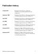
Publication history October 2006 Standard 1.04 of 703t Server Hardware Installation is issued for general release for CallPilot 4.0. September 2006 Standard 1.03 of 703t Server Hardware Installation is issued for general release for CallPilot 4.0. April 2006 Standard 1.02 of 703t Server Hardware Installation is issued for general release for CallPilot 4.0. July 2005 Standard 1.01 of 703t Server Hardware Installation is issued for general release for CallPilot 4.0. July 2005 Standard 1.
Publication history 8 Standard 1.
Task List To unpack the equipment ............................................................... 37 To remove the side panel ............................................................... 39 To inspect the server interior........................................................... 42 To replace the side cover ............................................................. 43 To install the chassis feet ............................................................. 45 To install the server ....................
Task List 10 Standard 1.
Contents 1 How to get Help 13 2 703t server description 15 Server features . . . . . . . . . . . . . . . . . . . . . . . . . . . . . . . . . . . . . . . . . . . . . . Slot assignments . . . . . . . . . . . . . . . . . . . . . . . . . . . . . . . . . . . . . . . . . . . . . Network connectivity . . . . . . . . . . . . . . . . . . . . . . . . . . . . . . . . . . . . . . . . . Supported peripheral devices . . . . . . . . . . . . . . . . . . . . . . . . . . . . . . . . . . . Reference documents . . . . .
Contents 12 Standard 1.
Chapter 1 How to get Help This section explains how to get help for Nortel products and services. Getting Help from the Nortel Web site The best way to get technical support for Nortel products is from the Nortel Technical Support Web site: http://www.nortel.com/support This site provides quick access to software, documentation, bulletins, and tools to address issues with Nortel products.
How to get Help Standard 1.04 Outside North America, go to the following Web site to obtain the phone number for your region: http://www.nortel.com/callus Getting Help from a specialist by using an Express Routing Code To access some Nortel Technical Solutions Centers, you can use an Express Routing Code (ERC) to quickly route your call to a specialist in your Nortel product or service. To locate the ERC for your product or service, go to: http://www.nortel.
Chapter 2 703t server description In this chapter Server features 16 Slot assignments 23 Network connectivity 25 Supported peripheral devices 30 Reference documents 31 703t Server Hardware Installation 15
703t server description Standard 1.04 Server features This section provides a general overview of the 703t server. Server dimensions Height chassis only: 420 mm (16.75 in.) with chassis feet: 440 mm (17.5 in.) Width chassis only: 215 mm (8.6 in.) with chassis feet: 320 mm (12.7 in.) Depth (distance from front to back) Clearance 650 mm (26 in.) front: 250 mm (10 in.) rear: 125 mm (5 in.) side: 75 mm (3 in.) Note: Additional side clearance is required for service.
October 2006 703t server description Environmental specifications Environmental condition Specification Operating temperature 10°C to 35°C (50°F to 95°F) Maximum rate of change must not exceed 10°C (50°F) per hour. Non-operating (storage) temperature -40°C to 70°C (-40°F to 158°F) Non-operating humidity 95%, non-condensing at 30°C (86°F) Altitude 1829 m (6000 ft) Electrostatic discharge 15 kV or more Acoustic noise 50 dBA in a typical office ambient temperature (18°C to 25°C [64.
703t server description Standard 1.
October 2006 703t server description The table below describes the parts that are identified in the preceding diagram: Part Function Reset button Triggers a hardware (cold) reset. Do not use this button to perform a server restart. Restart the server as described in “Restarting the server” in the Installation and Configuration Task List (555-7101-210).
703t server description 20 Standard 1.04 Part Function IDE CD-ROM drive (5.25 in.) Enables you to use the CallPilot software and documentation CD-ROMs. CD drive eject button Opens the CD-ROM drawer. Push the button again to close the drawer. Backup tape drive Allows backup of hard drive data. Hard drive 1 10,000 rpm hard drive Hard drive 2 10,000 rpm hard drive Drive bay Vacant Drive bay Vacant Drive bay Vacant Air flow slot Must remain empty for proper system cooling.
October 2006 703t server description Rear panel diagram The following diagram shows the 703t server’s rear panel features: Power connector PS/2 mouse connector USB connectors (future use) PS/2 keyboard connector Serial port (COM1) Parallel port Monitor connector 10/100/1000Base-T CLAN Ethernet connector (NIC2 1 GB) 10/100Base-T ELAN Ethernet connector (NIC1 10/100 MB) PCI slots Serial port (COM2) (not installed) 6 5 4 3 2 1 G101760 Note: For more information, see “Slot assignments” on page 23.
703t server description Standard 1.
October 2006 703t server description Slot assignments The slot assignment tables show the physical location of boards inside the server, relative to other boards the order in which boards are installed (for example, board #1, 2, 3, and so on) how the boards are represented in CallPilot Manager applications (that is, on the Maintenance Administration page) the maximum capacity for each switch connectivity Note: Your server may vary depending on what was ordered from Nortel; therefore, your
703t server description Standard 1.04 Slot definition and numbering In the following table, the term “slot” refers to the available slot openings in the chassis, not the PCI connectors inside the server. The slots are numbered from the bottom of the server to the top. Slot 1 is the bottom slot in the chassis when the chassis is standing upright.
October 2006 703t server description Network connectivity This section describes how the 703t server can be integrated into your network. The integration depends on the type of switch you are using. ATTENTION To secure the CallPilot server from unauthorized access, ensure that the CallPilot network is inside your organization’s firewall.
703t server description Standard 1.04 Sample network setup: Meridian 1 The Meridian 1 switch can be one of the following: Option 11C or Option 11C Mini using fiber connections Option 51C Option 61C Options 81 and 81C The following diagram shows a CallPilot 703t server network setup with a Meridian 1 switch.
October 2006 703t server description Sample network setup: Succession 1000 The following diagram shows a CallPilot 703t server network setup with a Succession 1000 system: Web-enabled CallPilot administrative PC i2004 Internet phonesets Desktop client PC Telephony LAN/Customer LAN (10/100/1000Base-T) Succession 1000 Internet Telephony Media Gateway Expansion Gateway Line Card Modem CallPilot server CE-MUX Internet Telephony Gateway Line Card Succession 1000 Call Server Router or Ethernet switch (o
703t server description Standard 1.04 In the previous diagram, the telephony LAN (TLAN) provides IP connectivity between the Succession 1000 system and the i2004 Internet phonesets. The connection between the Call Server and Media Gateway can be point-to-point, or it can be through the LAN, if the system is installed in a distributed data network.
October 2006 703t server description Network requirements Appropriate networking equipment must be available for the ELAN and the optional CLAN if it is used. The ELAN (and the optional CLAN if used) must be properly configured for correct CallPilot operation. To ensure correct configuration, Nortel recommends that you consult a network specialist. Remote access connectivity The RS-232 COM1 connector on the rear of the 703t server provides the connection to an external dial-up modem.
703t server description Standard 1.04 Supported peripheral devices This section identifies external devices that are supported by the 703t server. The following table describes the supported peripheral devices: Device Description Modem A 56 Kbps external modem (NTRH9078 in North America only) provides remote access to the 703t server. The modem connects to the RS-232 COM1 connector on the rear of the server.
October 2006 703t server description Reference documents CallPilot Customer Documentation Map Fundamentals CallPilot Fundamentals Guide (555-7101-010) Planning and Engineering Planning and Engineering Guide (555-7101-101) Network Planning Guide (555-7101-102) Data Networking for Voice over IP Guide (553-3001-160) Installation and Configuration Upgrade and Platform Migration Guide (555-7101-207) Installation and Configuration Task List Guide (555-7101-210) Server Installation Guides 201i Server Hardware
703t server description 32 Standard 1.
Chapter 3 Preinstallation requirements In this chapter Installation overview 34 Unpacking the 703t server 37 Removing the side cover 39 Inspecting the server interior 42 Replacing the side cover 43 Installing the chassis feet 45 703t Server Hardware Installation 33
Preinstallation requirements Standard 1.04 Installation overview Introduction This section provides an overview of the steps required to install the 703t server and peripheral devices. For detailed instructions, see Chapter 4, “Installing the server and connecting the peripheral devices.
October 2006 Preinstallation requirements Step Description 5 Place the 703t server in the chosen location (see page 48). ❒ 6 Set the DIP switches on the modem (see page 51). ❒ 7 Connect the 703t server and devices as follows: 8 Check Connect the monitor, keyboard, and mouse (see page 55). ❒ Connect the modem (see page 55). ❒ Connect the 703t server to the ELAN hub (see page 58). ATTENTION To comply with EMC requirements, a Class A hub must be located 10 m (33 ft.
Preinstallation requirements Standard 1.04 Conventions for warnings You may encounter the following types of warnings in this guide. Do not ignore them. DANGER Risk of electric shock . Warns you of an immediate electrical hazard, which, if not avoided, will result in shock, serious injury, or death. WARNING Risk of personal injury . Warns you of a situation in which you can be injured if instructions are not followed exactly as stated. CAUTION Risk of data loss or equipment damage .
October 2006 Preinstallation requirements Unpacking the 703t server Introduction Follow this procedure to unpack the server and peripherals. WARNING Risk of personal injury . The 703t CallPilot server weighs approximately 22 kg (46 lb) as shipped from manufacturing. If necessary, and to prevent personal injury, ask someone to help you unpack and position the server.
Preinstallation requirements Standard 1.04 5 Save all packing materials and cartons in case you must return any equipment to the carrier. What’s next? Remove the server side cover so that you can inspect the interior of the server. See “Removing the side cover” on page 39.
October 2006 Preinstallation requirements Removing the side cover Introduction This section describes how to remove the server side cover so that you can work with the interior components. The side cover is on the server’s left side when the front of the server is facing you. To remove the side panel WARNING Risk of personal injury . Be careful when you handle the sharp edges of the side panel and chassis to prevent personal injury. CAUTION Risk of equipment damage .
Preinstallation requirements Standard 1.04 The following diagram shows how to remove the side panel. See the instructions for removal below. 1 2 3 G101761 1 Place the server on its side on your working surface. 2 Turn the two thumbscrews on the back of the server counter-clockwise to loosen them. Note: The thumbscrews are not removable. Note: If a removable screw is present, remove it. This screw secures the cover to the server during shipping.
October 2006 Preinstallation requirements 4 Use one hand to pull the top edge of the cover away from the server to disengage the top row of tabs on the cover from the notches in the chassis. 5 Use both hands to lift the cover upward to disengage the bottom row of tabs from the notches in the chassis. 6 Set the cover aside. 7 Continue with “Inspecting the server interior” on page 42.
Preinstallation requirements Standard 1.04 Inspecting the server interior Introduction Before you install the server, you should perform a visual inspection for loose components, foreign matter, or shipping damage inside the server. CAUTION Risk of equipment damage . When working with interior components, use an ESD wrist strap to protect static-sensitive components. To inspect the server interior 1 Ensure that all the cards are fully seated on the baseboard.
October 2006 Preinstallation requirements Replacing the side cover Introduction When you are satisfied that the server was not damaged during shipment, reinstall the side cover. To replace the side cover CAUTION Risk of equipment damage . Ensure that there are no tools or loose parts inside the server chassis before replacing the side cover. 1 Align the right edge of the server side cover with the inside ledge at the front of the server. 2 Ensure that the cover lays flat along the side of the server.
Preinstallation requirements Standard 1.04 The following diagram shows how to: 1) align the tabs, 2) engage the cover, and 3) tighten the thumbscrews. Top and bottom tabs on cover Top and bottom slots in chassis 1 2 3 G101762 What’s next? If you want to install the chassis feet on the bottom of the server, continue with “Installing the chassis feet” on page 45. Otherwise, continue with the hardware installation. For more information, see “Installation checklist” on page 34.
October 2006 Preinstallation requirements Installing the chassis feet Introduction You can install feet on the bottom of the server. The feet stabilize the server and will help prevent the server from accidentally falling over on its side.
Preinstallation requirements Standard 1.04 1 Ensure that the server is laying on its side, supported to give the server bottom four to five inches clearance above the work surface. 2 Attach the feet as shown in the preceding diagram. Use four screws to attach each foot to the chassis. The holes in the feet line up with only one set of holes in the chassis, as follows: front foot: The middle hole is towards the front of the chassis. back foot: The middle hole is towards the back of the chassis.
Chapter 4 Installing the server and connecting the peripheral devices In this chapter Installing the server 48 Preparing the modem 49 Connecting peripherals to the server 53 Connecting the server to the ELAN 58 Connecting the server to the CLAN (optional) 60 Installing the Nortel software feature dongle 61 Connecting the server to power 63 703t Server Hardware Installation 47
Installing the server and connecting the peripheral devices Standard 1.04 Installing the server Before you install the 703t server, ensure that the chosen location meets the requirements identified in the “Site inspection checklist” provided in the Installation and Configuration Task List (555-7101-210). To install the server 1 Place the 703t server in its chosen location. Note: The server must be placed within 20 m (60 feet) of the Meridian 1 switch or Succession 1000 system.
October 2006 Installing the server and connecting the peripheral devices Preparing the modem You require a modem to support remote dial-up access to the CallPilot server. The modem also enables Nortel technical support to connect to your CallPilot server for troubleshooting purposes. Nortel connects to your server only when you request technical assistance.
Installing the server and connecting the peripheral devices Standard 1.
October 2006 Installing the server and connecting the peripheral devices To set the modem DIP switches Use a pair of tweezers or a small screwdriver to set the DIP switches as described in the “Change to” column of the following table: Note: ON is down. OFF is up. DIP switch Default setting Change to Function 1 OFF OFF Data Terminal Ready (DTR) override 2 3 4 5 OFF ON OFF ON OFF ON OFF ON 703t Server Hardware Installation OFF: Normal DTR operations.
Installing the server and connecting the peripheral devices DIP switch Default setting Change to Function 6 OFF OFF Carrier Detect (CD) override 7 8 OFF ON OFF ON Standard 1.04 OFF: The modem sends a CD signal when it connects with another modem; it drops the CD on disconnect. ON: CD is always on (override). Power-on and ATZ reset software defaults OFF: Loads Y or Y1 configuration from NVRAM. ON: Loads &F0-Generic template from read-only memory (ROM).
October 2006 Installing the server and connecting the peripheral devices Connecting peripherals to the server This section describes how to connect the monitor, keyboard, mouse, and modem to the server. Rear panel The peripheral device connection panel at the back of the server provides a legend that shows the symbol for each peripheral device and which connector to use. CAUTION Risk of system failure . You can install or use only Nortel-supplied peripheral devices on your server.
Installing the server and connecting the peripheral devices Standard 1.04 The diagram below shows the connectors for the power cord and the peripheral devices on the 703t server.
October 2006 Installing the server and connecting the peripheral devices To connect the mouse, keyboard, and monitor to the server 1 Place the monitor, keyboard, and mouse in the same location as the server. 2 Plug the keyboard and mouse into the appropriate PS/2 connectors on the chassis rear panel. See the diagram on page 54. 3 Plug in the monitor connector. Tighten the screws on the connector.
Installing the server and connecting the peripheral devices Standard 1.04 7 Connect the power cord to the modem, and plug the other end into a wall receptacle or power bar. 8 Turn on the modem.
October 2006 Installing the server and connecting the peripheral devices What’s next? Connect the server to the ELAN and CLAN hubs (if applicable). IF the server will THEN be connected to the ELAN continue with page 58. be connected only to a CLAN continue with page 60. not be connected to either the ELAN or CLAN continue with installing the software feature dongle. See page 61.
Installing the server and connecting the peripheral devices Standard 1.04 Connecting the server to the ELAN Connect the CallPilot server to the Meridian 1 switch or Succession 1000 system using the Embedded LAN (ELAN). ATTENTION ATTENTION For important considerations about using the ELAN in your network, see the Planning and Engineering Guide (555-7101-101). To comply with EMC requirements, a Class A hub must be located 10 m (33 feet) away from the 703t server.
October 2006 Installing the server and connecting the peripheral devices 3 At the switch, connect the ELAN network cable to an MAU (Ethernet) transceiver. Then complete the connection from the transceiver to the switch. DANGER Risk of fire hazard . The NTRH9069 MAU is not suitable for installation in ducts, plenums, or other spaces used for environmental air.
Installing the server and connecting the peripheral devices Standard 1.04 Connecting the server to the CLAN (optional) This section provides instructions to connect the server to the Customer LAN (CLAN). Note: The CLAN connection is optional. However, connection to a CLAN is required for support of desktop and web messaging users, or administration by means of a web-enabled PC. Make sure that your latest antivirus programs and Nortel security updates are installed.
October 2006 Installing the server and connecting the peripheral devices Installing the Nortel software feature dongle The software feature key is a security device that stores the unique serial number of the server. The feature key is embedded in the Nortel software feature dongle, which plugs into the parallel port.
Installing the server and connecting the peripheral devices Standard 1.04 Requirements For installation, you require a Phillips No. 1 screwdriver. To install the software feature dongle 1 Ensure that there is no cable connected to the parallel port. Note: The parallel port is also known as the printer port or LPT1. It is located at the back of the server. See the diagram on page 54.
October 2006 Installing the server and connecting the peripheral devices Connecting the server to power Before you begin Ensure that proper power and grounding are available for all the power outlets serving the CallPilot server and its associated peripherals. Power for these devices must be wired and fused independently of all other receptacles and referenced to the same ground as the PBX system.
Installing the server and connecting the peripheral devices Standard 1.
October 2006 Installing the server and connecting the peripheral devices WARNING Risk of personal injury and risk of hardware failure . You must connect the power outlets that are used by the CallPilot server and its peripheral devices to the same single-point ground reference as the one used by the switching system connected to the CallPilot server. If this requirement is not met, power transients can cause personal injury, hardware failure, or both.
Installing the server and connecting the peripheral devices 66 Standard 1.
Index Numerics B 703t server CLAN connection, establishing 60 connections establishing 63 power 63 dimensions 16 ELAN connection, establishing 58–59 environmental specifications 17 feet, installing 45–46 front panel, description 18–20 hard drive bays 20 installing 48 LEDs 19 PCI slots 22 peripheral device connections, diagram board labels, CallPilot Manager 24 63 peripheral devices, connecting 53 power connection, establishing 65 rear panel, description 53–54 side cover removing 39–41 replacing 43–44 s
Index side cover removing 40 replacing 44 software feature key adapter 61 TLAN (Succession 1000) 27 dimensions, 703t server 16 DIP switches, setting modem 51–52 dongle 61 E ELAN connecting server to 58–59 Embedded LAN See ELAN environmental specifications, 703t server 17 Ethernet hub 30 F fax modem diagram 50 required equipment 49 front panel, description 18–20 Standard 1.
October 2006 monitor 30 mouse 30 power connecting server to 65 grounding, requirement 65 protocols, supported network 28 R rear panel, description 21–22, 53–54 regulatory information 2 remote access connectivity 29 RS-232 connection 29 S serial number 61 server CLAN connection, establishing 60 connections establishing 63 power 63 dimensions 16 ELAN connection, establishing 58–59 environmental specifications 17 feet, installing 45–46 front panel, description 18–20 hard drive bays 20 installing 48 interior
Index 70 Standard 1.
703t Server Hardware Installation CallPilot Release 4.0 Document Number: 555-7101-226 Document Version: Standard 1.04 October 2006 To provide feedback or to report a problem in this document, go to http://www.nortel.com/documentfeedback All Rights Reserved. The information in this document is subject to change without notice. The statements, configurations, technical data, and recommendations in this document are believed to be accurate and reliable, but are presented without express or implied warranty.