Part No.
Copyright © 2001 Nortel Networks All rights reserved. March 2001. The information in this document is subject to change without notice. The statements, configurations, technical data, and recommendations in this document are believed to be accurate and reliable, but are presented without express or implied warranty. Users must take full responsibility for their applications of any products specified in this document. The information in this document is proprietary to Nortel Networks NA Inc.
EC Declaration of Conformity This product conforms (or these products conform) to the provisions of the R&TTE Directive 1999/5/EC.
1. License grant. Nortel Networks NA Inc.
5. Government licensees. This provision applies to all Software and documentation acquired directly or indirectly by or on behalf of the United States Government. The Software and documentation are commercial products, licensed on the open market at market prices, and were developed entirely at private expense and without the use of any U.S. Government funds. The license to the U.S. Government is granted only with restricted rights, and use, duplication, or disclosure by the U.S.
209564-A
Contents Preface . . . . . . . . . . . . . . . . . . . . . . . . . . . . . . . . . . . . . . . . . . . . . . . . . . . . . . 17 Before you begin . . . . . . . . . . . . . . . . . . . . . . . . . . . . . . . . . . . . . . . . . . . . . . . . . . . . . 17 Text conventions . . . . . . . . . . . . . . . . . . . . . . . . . . . . . . . . . . . . . . . . . . . . . . . . . . . . . 18 Related publications . . . . . . . . . . . . . . . . . . . . . . . . . . . . . . . . . . . . . . . . . . . . . . . . . . .
Contents Chapter 3 Installing the Passport 8683POS Module . . . . . . . . . . . . . . . . . . . . . . . . . . 35 Safety and environmental precautions . . . . . . . . . . . . . . . . . . . . . . . . . . . . . . . . . . . . . 35 Installing the Passport 8683POS Module . . . . . . . . . . . . . . . . . . . . . . . . . . . . . . . . . . 37 Verifying installation . . . . . . . . . . . . . . . . . . . . . . . . . . . . . . . . . . . . . . . . . . . . . . . . . . . 40 Initialization . . . . . . . . . . . . . .
Contents 9 Chapter 5 Graphing statistics in Device Manager . . . . . . . . . . . . . . . . . . . . . . . . . . . . 79 Overview . . . . . . . . . . . . . . . . . . . . . . . . . . . . . . . . . . . . . . . . . . . . . . . . . . . . . . . . . . . 79 Displaying statistics . . . . . . . . . . . . . . . . . . . . . . . . . . . . . . . . . . . . . . . . . . . . . . . . . . . 80 Viewing POS statistics . . . . . . . . . . . . . . . . . . . . . . . . . . . . . . . . . . . . . . . . . . . . . .
Contents show ports stats pos lqrstatus . . . . . . . . . . . . . . . . . . . . . . . . . . . . . . . . . . . . . . . 115 show ports stats pos pathcurrent . . . . . . . . . . . . . . . . . . . . . . . . . . . . . . . . . . . . . 116 show ports stats pos pathinterval . . . . . . . . . . . . . . . . . . . . . . . . . . . . . . . . . . . . 117 show ports stats pos pppiftbl . . . . . . . . . . . . . . . . . . . . . . . . . . . . . . . . . . . . . . . . 118 show ports stats pos sectioncurrent . . . . . . . .
Figures Figure 1 Passport 8683POS Module . . . . . . . . . . . . . . . . . . . . . . . . . . . . . . . . . . . 25 Figure 2 1-port OC-12c/STM-4 MDA . . . . . . . . . . . . . . . . . . . . . . . . . . . . . . . . . . . 26 Figure 3 2-port OC-3c/STM-1 MDA . . . . . . . . . . . . . . . . . . . . . . . . . . . . . . . . . . . . 26 Figure 4 Passport 868POS module with an OC-12c/STM-4 MDA . . . . . . . . . . . . . 27 Figure 5 Removing the filler panel . . . . . . . . . . . . . . . . . . . . . . . . . .
Figures Figure 31 graphSonetPort dialog box — Path tab . . . . . . . . . . . . . . . . . . . . . . . . . . 88 Figure 32 graphSonetPort dialog box — FE Path tab . . . . . . . . . . . . . . . . . . . . . . . 89 Figure 33 config pos info command sample output . . . . . . . . . . . . . . . . . . . . . . . . . 98 Figure 34 show ports info pos all command output . . . . . . . . . . . . . . . . . . . . . . . .
Tables Table 1 Passport 8683POS Module online LED indications . . . . . . . . . . . . . . . . . 27 Table 2 MDA LED indications . . . . . . . . . . . . . . . . . . . . . . . . . . . . . . . . . . . . . . . . 28 Table 3 Passport 8683POS Module access levels . . . . . . . . . . . . . . . . . . . . . . . . 47 Table 4 Passport Device Manager port color codes . . . . . . . . . . . . . . . . . . . . . . . 49 Table 5 Passport Device Manager buttons . . . . . . . . . . . . . . . . . . . . . . . . . . .
Tables Table 30 config poscard command parameters and variables . . . . . . . . . . . . . . . . 93 Table 31 config pos command parameters and variables . . . . . . . . . . . . . . . . . . . . 94 Table 32 config pos ip command parameters and variables . . . . . . . . . . . . . . . . . 95 Table 33 config pos ppp command parameters and variables . . . . . . . . . . . . . . . . 96 Table 34 config pos sonet command parameters and variables . . . . . . . . . . . . . . .
Tables 15 Table 52 Information fields for output of the show tech command . . . . . . . . . . . . 126 Table 53 test led command parameters and variables . . . . . . . . . . . . . . . . . . . . . 129 Table 54 System page fields . . . . . . . . . . . . . . . . . . . . . . . . . . . . . . . . . . . . . . . . . 133 Table 55 SONET page fields . . . . . . . . . . . . . . . . . . . . . . . . . . . . . . . . . . . . . . . . . 135 Table 56 Link page fields . . . . . . . . . . . . . . . . . . . . . . . . .
Tables 209564-A
Preface The Passport® 8683POS Module is part of the Nortel Networks Passport® 8600 Series line of communications products. This module is the Passport Packet over SONET (POS) module for the Passport 8600 chassis. This guide describes the features and operations of the Passport 8683POS Module and provides instructions for installing and managing the module.
Preface Text conventions This guide uses the following text conventions: angle brackets (< >) Indicate that you choose the text to enter based on the description inside the brackets. Do not type the brackets when entering the command. Example: If the command syntax is ping , you enter ping 192.32.10.12 bold Courier text Indicates command names and options and text that you need to enter. Example: Use the dinfo command. Example: Enter show ip {alerts|routes}.
Preface 19 italic text Indicates new terms, book titles, and variables in command syntax descriptions. Where a variable is two or more words, the words are connected by an underscore. Example: If the command syntax is show at , valid_route is one variable and you substitute one value for it. plain Courier text Indicates command syntax and system output, for example, prompts and system messages. Example: Set Trap Monitor Filters separator ( > ) Shows menu paths.
Preface Related publications For more information about Passport 8600 series products and management software, refer to the following publications: • • • • • • • • • • • Installing the Passport 8683POS Module MDAs (part number 209565-A) Getting Started with the Passport 8000 Series Management Software (part number 209663-C) Using the Passport 8600 Modules (part number 207306-C) Installation Instructions for the Passport 8600 Modules (part number 207372-C) Networking Concepts for the Passport 8000 Seri
Preface 21 How to get help If you purchased a service contract for your Nortel Networks product from a distributor or authorized reseller, contact the technical support staff for that distributor or reseller for assistance.
Preface 209564-A
Chapter 1 About the Passport 8683POS Module The Passport 8683POS Module provides network transmission using packet over Synchronous Optical Network (SONET) services. The Passport 8683POS Module for the Passport 8600 series routing switches provides WAN support to the Passport product line by allowing access to SONET services in the metropolitan area. Where multiple campuses exist in a single metropolitan area, you can connect these campuses without compromising performance or increasing complexity.
Chapter 1 About the Passport 8683POS Module Refer to Networking Concepts for the Passport 8000 Series Switch, Release 3.1 for a thorough discussion of the complete functionality of the Passport product line, including the Passport 8683POS Module.
Chapter 1 About the Passport 8683POS Module • • • 25 — PPP over SONET: RFC 2615 — SONET/SDH: RFC 2558 — PPP: RFC 1471, RFC 1473, RFC 1474, and RFC 1661 — LQM: RFC 1989 — SNMP: RFC 1213 — IPCP: RFC 1332 — IPXCP: RFC1552 — BCP: RFC 1638_ Multiple spanning tree groups - bridge mode only Manageable through the Passport CLI or Device Manager, the SNMP-based graphical user interface Monitored through a World Wide Web browser from anywhere on the network Physical description The Passport 8683POS Module (Figure
Chapter 1 About the Passport 8683POS Module Media dependent adapters The Passport 8683POS Module has slots for three media dependent adapters (MDAs) that have their own LEDs. You can use up to three of the following MDAs with the Passport 8683POS Module: • • 1-port OC-12c/STM-4: SMF or MMF using SONET/SDH 2-port OC-3c/STM-1: SMF or MMF using SONET/SDH You can mix these MDAs on the Passport 8683POS Module. Figure 2 shows the OC-12c/STM-4 MDA, and Figure 3 shows the OC-3c/STM-1 MDA.
Chapter 1 About the Passport 8683POS Module 27 Figure 4 shows the Passport 8683POS Module with the OC-12c/STM-4 MDA installed. (For information on installing the MDAs, refer to Installing the Passport 8683POS Module MDAs.
Chapter 1 About the Passport 8683POS Module MDA LEDs Table 2 lists the MDA LED indications.
Chapter 2 Using the Passport 8683POS Module A typical application consists of a single Passport 8683POS Module in an Passport 8600 series switch, but multiple modules are also supported. This chapter briefly explains how the Passport 8683POS Module operates within the Passport switch.
Chapter 2 Using the Passport 8683POS Module SONET terms and acronyms This section provides a brief listing of common Synchronous Optical Network (SONET) terms. SONET is a medium for transmitting data that uses fiber-optic cables. The following terms and acronyms are frequently used with SONET information: • • • • • • SONET: Synchronous Optical Network. SONET is a family of fiber optic transmission rates that provides the flexibility to transport many digital signals with different capacities.
Chapter 2 Using the Passport 8683POS Module • • 31 Single-mode fiber (SMF) Multimode fiber (MMF). Note: The estimated maximum transmission distance for OC-3c SMF is 20 kilometers (km); for OC-3c MMF is 2 km; for OC-12c SMF is 15 km; for OC-12c MMF is 500 m. Point-to-Point Protocol The PPP family of protocols is divided into three categories: • • • Control protocols control operation and maintenance of the PPP link.
Chapter 2 Using the Passport 8683POS Module For example, a configure-request packet may specify the link’s maximum transmission unit (MTU) size. The configure-request packet contains the user-configured values, which the sending device and the receiving device may need to negotiate.
Chapter 2 Using the Passport 8683POS Module 33 Negotiating network layer protocols PPP uses various network control protocols to determine the values of parameters during network layer negotiations, which is the final phase of PPP initialization. Similar to the LCP, each network control protocol allows the devices to negotiate various network options over the data link by transmitting configure-request, configure-ACK, configure-NAK, and configure-reject packets.
Chapter 2 Using the Passport 8683POS Module 209564-A
Chapter 3 Installing the Passport 8683POS Module This chapter describes the procedure for installing the Passport 8683POS Module.
Chapter 3 Installing the Passport 8683POS Module • When handling modules, do not touch components on the modules; always handle modules by their edges. Store unused modules in their protective packaging. Warning: Fiber optic equipment can emit laser or infrared light that can injure your eyes. Never look into an optical fiber or connector port. Always assume that fiber optic cables are connected to a light source. Vorsicht: Glasfaserkomponenten können Laserlicht bzw.
Chapter 3 Installing the Passport 8683POS Module 37 Installing the Passport 8683POS Module To install the Passport 8683POS Module: 1 Remove the filler panel from the module slot in the Passport 8000 series chassis (Figure 5). Figure 5 Removing the filler panel 9058FB Note: If you are removing a module from the slot in which you want to place the new Passport 8683POS Module, be sure to: • Remove all port interface cables • Release the insertor/extractor levers of the I/O module, and swing them out.
Chapter 3 Installing the Passport 8683POS Module Figure 6 Extending the inserter/extractor levers 9059FA Note: Always handle an I/O module by the sides and carefully slide it out of the chassis. Place the module on a grounded work surface and in an antistatic bag for storage. 3 Handling the Passport 8683POS Module by the sides only, carefully align it with the card guides in the chassis. Slide the module into the slot until the module connectors touch the chassis backplane (Figure 7).
Chapter 3 Installing the Passport 8683POS Module 39 Figure 8 Closing the inserter/extractor levers MDA 1 MDA 2 8672 ATM Online 10037FA 5 Tighten the retaining screws (Figure 9). Figure 9 Tightening the retainer screws MDA 1 MDA 2 8672 ATM Online 10038FA 6 Connect the interface cables. You must install at least one MDA on the Passport 8683POS Module in order to pass traffic. For instructions on installing MDAs, refer to Installing the Passport 8683POS Module MDAs.
Chapter 3 Installing the Passport 8683POS Module Verifying installation The Passport 8683POS Module front panel has an Online LED that indicates whether or not the module has power applied and is initialized correctly. For information on online LEDs, see “Online LED” on page 27. Note: You cannot configure the Passport 8683POS Module until the online LED on the module is steadily lit and you have inserted at least one MDA.
Chapter 3 Installing the Passport 8683POS Module 41 The Passport 8683POS Module requests a redownload from the Passport 8690SF module, and the screen displays this message: Redownload requested by POS card in slot . The Passport 8683POS Module attempts a redownload three times. If the download is still unsuccessful, the Passport 8683POS Module goes offline and the screen displays this message: Redownload of POS card in slot failed maximum 3 times; POS card is offline.
Chapter 3 Installing the Passport 8683POS Module If you have one MDA installed, you can proceed to configure the Passport 8683POS Module. Note: You must save your configuration (using either the CLI or Device Manager) to preserve the configuration changes you made to the Passport 8683POS Module across reboots.
Chapter 3 Installing the Passport 8683POS Module 43 Replacing a module You can hot-swap Passport 8683POS Modules as long as the module you are removing has the same MDAs installed as the module you are inserting. In this case, the system saves the configuration. If you hot-swap the module with a module that has different MDAs installed, you must reconfigure the module.
Chapter 3 Installing the Passport 8683POS Module 209564-A
Chapter 4 Managing the Passport 8683POS Module Two management tools enable you to manage the Passport 8683POS Module: Device Manager and command line interface (CLI). You can also use the embedded web-based management feature to monitor the Passport 8683POS Module. See Chapter 7, “Web management,” on page 131 for information on using the web-based management feature.
Chapter 4 Managing the Passport 8683POS Module slot regardless of the actual physical number of ports. Port numbers 3 and 4 apply to the MDA in the middle slot regardless of the actual physical number of ports; and port numbers 5 and 6 apply to the MDA in the right slot regardless of the physical number of ports.
Chapter 4 Managing the Passport 8683POS Module 47 For detailed information on all aspects of installing and running Device Manager, refer to: • • • Getting Started with the Passport 8000 Series Management Software Reference for Passport 8000 Series Management Software Routing Operations, and Reference for Passport 8000 Series Management Software Switching Operations. This section describes the Device Manager features that are specific to the Passport 8683POS Module.
Chapter 4 Managing the Passport 8683POS Module When you launch Device Manager, a graphical image of the Passport 8600 chassis with the Passport 8683POS Module installed is displayed (Figure 10).
Chapter 4 Managing the Passport 8683POS Module 49 The ports on the graphical image are color-coded to provide at-a-glance port status. Table 4 shows the status assigned to each color code. Table 4 Passport Device Manager port color codes Field Description Green Port is operating. Red Port has been manually disabled. Orange Port has no link. Light blue Port is in standby mode. Dark blue Port is being tested. Gray Port is unmanageable.
Chapter 4 Managing the Passport 8683POS Module Resetting the module To reset the module: 1 Highlight the card. 2 Choose Edit > Card. The Card dialog box opens with the Card tab displayed (Figure 11).
Chapter 4 Managing the Passport 8683POS Module 51 Table 6 describes the fields in the Card tab. Table 6 Card tab fields Field Description FrontType Card type. FrontDescription Packet Over Sonet. FrontAdminStatus The administrative status of the card. FrontOperStatus The operational status of the card. FrontSerialNum Serial number of card. FrontHwVersion Hardware version. FrontPartNumer Part number. FrontDateCode Date code. FrontDeviations Deviations. BackType Card back type.
Chapter 4 Managing the Passport 8683POS Module Table 7 describes the fields in the POS tab. Table 7 POS tab fields Field Description Action: reset Resets the card. ImageFileName Name of the image file which downloads at initialization. 4 Click reset. 5 Click Apply. To reset the card using the CLI, see “Configuration commands” on page 92. Viewing MDA information To view information on the MDA you are using: 1 Highlight the MDA. 2 Select Edit > Mda. The MDA dialog box opens (Figure 13).
Chapter 4 Managing the Passport 8683POS Module 53 Table 8 describes the fields in the MDA dialog box.
Chapter 4 Managing the Passport 8683POS Module Configuration procedures You can configure the Passport 8683POS Module in two basic modes: • • Bridging: Bridging mode is enabled by default. Bridging is configured for connections between two Passport 8683POS Modules and between Passport 8683POS Modules and other devices that support PPP bridging. Routing: You select routing mode for connections between your Passport 8683POS Module and other POS-capable routers for IP and IPX routing.
Chapter 4 Managing the Passport 8683POS Module 55 Table 9 Passport 8683POS Module default settings (continued) Parameter Default Lock False Lqr interval 100 Lqr status Enabled Lqr threshold 95 Magic number True Oversize frame Disabled Perform tagging Disabled Scramble Enabled Signal-Label (C2) 0x16 Section trace (J0) 1 (0x01) STP RFC 1638 Enabled Tagged frame discard Disabled Unknown MAC discard Disabled Untagged frame discard Disabled Device Manager interval 10 seconds Bas
Chapter 4 Managing the Passport 8683POS Module Figure 14 Port dialog box — Interface tab 209564-A
Chapter 4 Managing the Passport 8683POS Module 57 Table 10 describes the Interface tab items. Table 10 Interface tab items Item Description Index Unique value assigned to each interface. The value ranges between 16 and 255. Name Displays the name of this port. To assign or change a name to the port, highlight the field and enter alphanumeric characters. Descr Type of interface, either: • OC-3c MMF or SMF • OC-12c MMF or SMF Type Media type of this interface.
Chapter 4 Managing the Passport 8683POS Module Table 10 Interface tab items (continued) Item Description LastChange Value of sysUpTime at the time the interface entered its current operational state. If the current state was entered prior to the last reinitialization of the local network management subsystem, the value is zero. LinkTrap Sets whether or not link Up/link Down traps should be generated for this interface.
Chapter 4 Managing the Passport 8683POS Module 59 Enabling or disabling a port Note: When you change configurations in Device Manager, and hit the Apply button, the system will disable and re-enable the port automatically. You can enable or disable a port by two methods. To enable or disable a port through the Device Manager menu bar: 1 Highlight the port. 2 From the Device Manager menu bar, choose Edit > Port. The Port dialog box opens with the Interface tab displayed (Figure 14 on page 56).
Chapter 4 Managing the Passport 8683POS Module 2 Choose Edit > Port. The Port dialog box opens with the Interface tab displayed (Figure 14 on page 56). 3 Disable the port as described in “Enabling or disabling a port” on page 59. 4 In the Interface tab, click the POS SONET tab. The POS SONET tab opens (Figure 15).
Chapter 4 Managing the Passport 8683POS Module 61 Table 11 describes the items in the POS SONET tab. Table 11 POS SONET tab items Item Description SonetFraming Sets the framing for the port to: • SONET—Synchronous Optical Network format; standard format used in North America (default) • SDH—Synchronous Digital Hierarchy clock format; standard format used in Europe. SonetOperStatusFraming Operational value of SONET framing.
Chapter 4 Managing the Passport 8683POS Module 5 Select the SonetClockSource, either line or internal. If two Passport POS Modules are operating directly (that is, connected back to back, without any intervening Sonet equipment), one port must provide the clock source. Set the clock source of one port to internal, and the opposite port must be set to line. 6 Select other SONET parameters. 7 Click Apply. 8 Re-enable the port as described in “Enabling or disabling a port” on page 59.
Chapter 4 Managing the Passport 8683POS Module 63 Configuring routing A POS port configured for IPCP and/or IPXCP encapsulation must be the sole member of the VLAN. You cannot add any other port to a VLAN which already has a POS port with IPCP and/or IPXCP encapsulation enabled. You cannot add a POS port which is configured for IPCP and/or IPXCP encapsulation to a VLAN which already has other ports as members.
Chapter 4 Managing the Passport 8683POS Module Figure 16 Port dialog box — POS PPP tab 209564-A
Chapter 4 Managing the Passport 8683POS Module 65 Table 12 describes the POS PPP tab items Table 12 POS PPP tab items Area Item Description Link LinkConfigMagicNumber If set to enable, selects a random number (“magic number”) used in loopback detection. Enable detects loopback; disable does not detect loopback. OperStatusLinkMagicNumber Operational value of LinkConfigMagicNumber. Bridge IP IPX LinkConfigFcsSize Configures the size (in bits) of cyclic redundancy check field used in PPP frame.
Chapter 4 Managing the Passport 8683POS Module 5 To enable IP routing, in the IpConfigAdminStatus field, click open. 6 To configure an IP address for the port: a Highlight the port. b Choose Edit > Port. The Port dialog box opens with the Interface tab displayed (Figure 14 on page 56). c Click the IP Address tab. The IP address tab opens (Figure 17). Figure 17 Port dialog box — IP Address tab Table 13 describes the fields in the IP Address tab.
Chapter 4 Managing the Passport 8683POS Module 67 Figure 18 Port, Insert IP Address dialog box Table 14 describes the Port, Insert IP Address dialog box items. Table 14 Insert IP Address dialog box items Item Description Ip Address IP address to which the entry’s addressing information pertains. Net Mask The subnet mask associated with the IP address of the entry. VlanId Unique VLAN identifier. e Type the IP address and click Insert.
Chapter 4 Managing the Passport 8683POS Module 3 To configure IP routing, enter: config pos > ppp ip-admin-status open 4 To configure an IP address on the selected port on both Passport 8683POS Modules, enter: config pos ip create 5 To enable the selected port on both Passport 8683POS Modules, enter: config pos state enable See Chapter 6, “Command line interface,” on page 91 for descriptions of the CLI commands.
Chapter 4 Managing the Passport 8683POS Module 69 The VLAN dialog box opens with the Basic tab displayed (Figure 19). Figure 19 VLAN dialog box — Basic tab Table 15 describes the fields in the Basic tab. Table 15 Basic tab fields Field Description Id Unique VLAN identifier. Name An administratively-assigned name for this VLAN. ColorIdentifier An administratively-assigned color code for this VLAN.
Chapter 4 Managing the Passport 8683POS Module Table 15 Basic tab fields (continued) Field Description SubnetAddr IP subnet address of this VLAN. This value is meaningful only if rcVlanType is equal to byIpSubnet(2). For other VLAN types it should have the value 0.0.0.0. SubnetMask IP subnet mask of this VLAN. This value is meaningful only if rcVlanType is equal to byIpSubnet(2). For other VLAN types it should have the value 0.0.0.0.
Chapter 4 Managing the Passport 8683POS Module 71 Configuring IPX routing using the CLI To configure the Passport 8683POS Modules for IPX routing using the CLI: 1 Configure a protocol-based VLAN. and assign the port to the VLAN as a static member and ensure that no other ports are allowed to join. Refer to Reference for Passport 8000 Management Software Routing Operations for information on how to configure VLANs using CLI.
Chapter 4 Managing the Passport 8683POS Module Figure 20 Chassis dialog box — System tab 3 Click the Trap Receivers tab. The Trap Receivers tab opens (Figure 21).
Chapter 4 Managing the Passport 8683POS Module 73 Table 16 describes the fields in the Trap Receivers tab. Table 16 Trap Receivers tab fields Field Description IpAddress IP address to which the entry’s addressing information pertains. Community Community string used for trap messages to this trap receiver. Version Version 4 Click Insert. The Chassis, Insert Trap Receivers dialog box opens (Figure 22).
Chapter 4 Managing the Passport 8683POS Module Viewing the Trap Log To view the Trap Log that contains SONET-specific traps: Click the bell icon on the toolbar. The Trap dialog box opens (Figure 23). Figure 23 Trap Log dialog box Table 18 describes the fields in the Trap Log dialog box. Table 18 Trap Log dialog box fields 209564-A Field Description Node IP address of the device sending SONET trap. Time Timestamp in the trap. Type Type of SONET trap: Section/Line/Path alarm.
Chapter 4 Managing the Passport 8683POS Module 75 SONET loopback test feature This section describes the loopback test features in Device Manager available for the Passport 8683POS Module. For information on the CLI test commands, see “Test commands” on page 127. Note: All ports must be in test mode to conduct any testing. To test for loopback: 1 Highlight the port. 2 Choose Edit > port. The Port dialog box opens with the Interface tab displayed (Figure 14 on page 56).
Chapter 4 Managing the Passport 8683POS Module Table 19 Test tab items Item Description Result Result of the test. Code Code used for test. PassCount Number of events which passed the test. FailCount Number of events which failed the test. 6 Click Ext. Loopback to test the external loopback or click Int. Loopback to test the internal loopback. A dialog box displays the test results. 7 Click Stop to cease testing. 8 Click Close. 9 Click the Interface tab.
Chapter 4 Managing the Passport 8683POS Module 77 Alarms Using Device Manager or the CLI, you can enable RMON globally or on a port-by-port basis. Implementing RMON lets you set alarms relating to specific events or variables. Refer to Reference for the Passport 8000 Series Management Software Switching Operations for more information on alarms. Table 20 lists the alarms that are specific to the Passport 8683POS Module. The alarms are listed in order of priority.
Chapter 4 Managing the Passport 8683POS Module 209564-A
Chapter 5 Graphing statistics in Device Manager This chapter contains information on the following topics: • • “Overview,” next “Displaying statistics” on page 80 For more information about using Passport Device Manager, refer to Reference for Passport 8000 Series Management Software Switching Operations, Release 3.1 and Reference for Passport 8000 Series Management Software Routing Operations, Release 3.
Chapter 5 Graphing statistics in Device Manager Table 21 Types of statistics Field Description AbsoluteValue The total count since the last reset of counters. A system reboot resets all counters. Cumulative The total count since the statistics tab was first opened. The elapsed time for the cumulative counter is displayed at the bottom of the statistics window. Average The cumulative count divided by the cumulative elapsed time.
Chapter 5 Graphing statistics in Device Manager 81 Note: The windows displaying statistics are read-only. Viewing POS statistics To display statistics POS statistics: 1 On the device view, right-click the port. 2 Choose Graph POS. The graphSonetPort dialog box opens with the POS tab displayed (Figure 25). Figure 25 graphSonetPort dialog box — POS tab Table 22 describes the fields in the POS tab.
Chapter 5 Graphing statistics in Device Manager Table 22 POS tab fields (continued) Field Description HCInOctets The total number of octets received on the interface, including framing characters. HCInUcastPkts Number of packets delivered by this sub-layer to a higher (sub-)layer, which were not addressed to a multicast or broadcast address at this sub-layer.
Chapter 5 Graphing statistics in Device Manager 83 The graphSonetPort dialog box opens with the POS statistics tab displayed (Figure 25). 3 Click the PPP Link tab. The PPP Link tab opens (Figure 26). Figure 26 graphSonetPort dialog box — PPP Link tab Table 23 describes the fields in the PPP Link tab. Table 23 PPP Link tab fields Field Description BadAddresses Number of packets received with an Incorrect Address Field.
Chapter 5 Graphing statistics in Device Manager Viewing PPP LQR To display PPP LQR statistics: 1 On the device view, right-click the port. 2 Choose Graph Port. The graphSonetPort dialog box opens with the POS statistics tab displayed (Figure 25). 3 Click the PPP LQR tab. The PPP LQR tab opens (Figure 27). Figure 27 graphSonetPort dialog box — PPP LQR tab Table 24 describes the fields in the PPP LQR tab.
Chapter 5 Graphing statistics in Device Manager 85 Table 24 PPP LQR tab fields Field Description Quality Quality number. InGoodOctets Number of good octets received on the interface. LocalPeriod Time interval in 100th of a second between link quality reporting from local end. RemotePeriod Time interval in 100th of a second between link quality reporting from remote end. OutLQRs Value of the OutLQRs counter on the local node for the link.
Chapter 5 Graphing statistics in Device Manager Table 25 describes the fields in the Section tab. Table 25 Section tab fields Field Description ESs Errored Second (ES) is a second with one or more Coding Violations or one or more incoming defects, for example, SEF, LOS, AIS, LOP. SESs Severely Errored Second (SES) is a second with x or more CVs, or a second during which at least one or more incoming defects.
Chapter 5 Graphing statistics in Device Manager 87 Table 26 Line tab fields Field Description ESs Errored Second (ES) is a second with one or more Coding Violations or one or more incoming defects, for example, SEF, LOS, AIS, or LOP. SESs Severely Errored Second (SES) is a second with x or more CVs, or a second during which at least one or more incoming defects. CVs Coding Violations (CV) are Bit Interleaved Parity (BIP) errors that are detected in the incoming signal.
Chapter 5 Graphing statistics in Device Manager Table 27 describes the fields in the FE Line tab. Table 27 FE Line tab fields Field Description ESs Errored Second (ES) is a second with one or more Coding Violations or one or more incoming defects, for example, SEF, LOS, AIS, or LOP. SESs Severely Errored Second (SES) is a second with x or more CVs, or a second during which at least one or more incoming defects.
Chapter 5 Graphing statistics in Device Manager 89 Table 28 describes the fields in the Path tab. Table 28 Path tab fields Field Description ESs Errored Second (ES) is a second with one or more Coding Violations or one or more incoming defects, for example, SEF, LOS, AIS, or LOP. SESs Severely Errored Second (SES) is a second with x or more CVs, or a second during which at least one or more incoming defects.
Chapter 5 Graphing statistics in Device Manager Table 29 describes the fields in the FE Path tab. Table 29 FE Path tab fields 209564-A Field Description ESs Errored Second (ES) is a second with one or more Coding Violations or one or more incoming defects, for example, SEF, LOS, AIS, or LOP. SESs Severely Errored Second (SES) is a second with x or more CVs, or a second during which at least one or more incoming defects.
Chapter 6 Command line interface This chapter contains information about the CLI commands relevant to the Passport 8683POS Module. For more information about the CLI for Passport 3.1, refer to: • • • Getting Started with Passport 8000 Series Management Software, Release 3.1 Reference for the Passport 8000 Series Command Line Interface Switching Operations, Release 3.1 Reference for the Passport 8000 Series Command Line Interface Routing Operations, Release 3.
Chapter 6 Command line interface Configuration commands This section describes the configuration commands available with the Passport 8683POS Module. There are two types of configuration commands: • • Module commands Port commands Note: If you replace one card with another type of card, Nortel Networks recommends that you go to the root level of the CLI directory before you use any CLI commands.
Chapter 6 Command line interface 93 Table 30 config poscard command parameters and variables Parameters and variables Description card-reset Resets the card. debug Enables or disables trace messages on the module to be displayed on the console of the switch. info Displays the image filename and debug mode for the module. pos-console Prints the trace message POS card. This is a priv command.
Chapter 6 Command line interface Table 31 config pos command parameters and variables Parameters and variables Description default-vlan-id Directs the switch to send the untagged frames to a default VLAN if received on a tagged port. is the VLAN ID of the default VLAN to which the discarded frames are sent. info Shows the last saved port settings and the next-level CLI commands. Note that this does not show the current settings, but the last saved settings.
Chapter 6 Command line interface 95 Table 32 config pos ip command parameters and variables Parameters and variables Description create [mac_offset ] Creates an IP address and assigns it to a VLAN, with the VLAN ID. delete Deletes the IP address. info Shows the last saved port settings and the next-level CLI commands. Note that this does not show the current settings, but the last saved settings.
Chapter 6 Command line interface Table 33 config pos ppp command parameters and variables Parameters and variables Description bridge-admin-status Enables or disables the bridge control protocol. fcs-size<32 | 16> Sets the length of the redundancy check (fcs) to either 32 or 16. info Shows the last saved port settings and the next-level CLI commands. Note that this does not show the current settings, but the last saved settings.
Chapter 6 Command line interface 97 Table 34 config pos sonet command parameters and variables Parameters and variables Description clock-source Sets the clock source to: • , which means clocking is derived from on-board clock. • , which means clocking is derived from line. Note that if you have two connected modules, you must set both to internal or one to line and one to internal; do not set both to line.
Chapter 6 Command line interface Table 35 describes the parameters and variables for the config pos stg command. Table 35 config pos stg command parameters and variables Parameters and variables Description faststart Enables or disables the fast start flag. info Shows the last saved port settings and the next-level CLI commands. Note that this does not show the current settings, but the last saved settings. pathcost Sets the contribution of this port to the path cost.
Chapter 6 Command line interface 99 Show commands This section describes the show commands available with the Passport 8683POS Module.
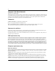
Chapter 6 Command line interface show ports info pos The show ports info pos command displays information (Figure 34) about the configuration for a specified port on the Passport 8683POS Module.
Chapter 6 Command line interface 101 Figure 34 show ports info pos all command output Passport-8610:5/show/ports/info/pos# all ======================================================================== SONET Config Info ======================================================================== PORT FRAMING CLOCK SECTION SIGNAL NUM MODE SOURCE TRACE LABEL SCRAMBLE -----------------------------------------------------------------------10/1 sonet line 1 0x16 enable 10/3 sonet internal 1 0x16 enable =============
Chapter 6 Command line interface Figure 35 show ports info pos all command output (continued) PORT PPP FCS IPX ROUTE LQR-QUAL LQR-QUAL NUM LQSTATUS MRU SIZE PROTOCOL THRESHOLD PERIOD REMOTE IP ----------------------------------------------------------------------------10/1 enable 1936 32 none 95 100 10.32.6.14 10/3 enable 1936 32 none 95 100 10.32.6.
Chapter 6 Command line interface 103 . Table 36 Information fields for output of the show ports info pos all command Field Description PORT NUM Port number. FRAMING MODE Indicates whether the framing mode is either: • sonet • sdh CLOCK SOURCE Indicates whether the clock source is either: • line • internal SECTION TRACE Indicates the integer that the section trace flag (j0) is set to. SIGNAL LABEL Operational value of Path Signal Label (C2).
Chapter 6 Command line interface Table 36 Information fields for output of the show ports info pos all command (continued) Field Description MRU Size (in octets) of the largest packet that can be sent or received on the interface. For IPCP and IPXCP, the maximum is 1936. When BCP is enabled, however, the maximum is 1934. Check which NCP is enabled before configuring the Mru. Note: The Bridge Control Protocol (BCP) is enabled on the Passport 8683POS Module by default.
Chapter 6 Command line interface 105 Figure 36 show ports stats pos activealarms command output Passport-8610:5/show/ports# stats pos activealarms ======================================================= Active Alarms ======================================================= PORT NUM ACTIVE ALARM --------------------------------------------------------10/5 No Defect 10/6 LOS Passport-8610:5/show/ports/stats/pos# Table 37 describes the information fields for output for the show ports stats pos activealarms
Chapter 6 Command line interface Figure 37 show ports stats pos felinecurrent command output Passport-8610:5/show/ports/stats/pos# felinecurrent ====================================================================== POS Far End Line Current Stats ====================================================================== PORT ERRORED SECONDS SEVERELY ERRORED CODE VIOLATION UNAVAILABLE NUM COUNT (ES) COUNT (SES) COUNT (CV-L) SECONDS(UAS) ---------------------------------------------------------------------
Chapter 6 Command line interface 107 show ports stats pos felineinterval This command displays statistics (Figure 38) on the far end line over a 15-minute interval. You specify which interval, or span of intervals, to display for the command.
Chapter 6 Command line interface Table 39 Information fields for output of the show ports stats pos felineinterval command Field Description PORT NUM Port number. ERRORED SECONDS COUNT (ES) Errored Second (ES) is a second with one or more Coding Violations (CV) or one or more incoming defects (for example, SEF, LOS, AIS, LOP). SEVERELY ERRORED COUNT (SES) Severely Errored Second (SES) is a second with x or more CVs, or one or more incoming defects.
Chapter 6 Command line interface 109 Table 40 describes the information fields for output of the show ports stats pos fepathcurrent command. Table 40 Information fields for output of the show ports stats pos fepathcurrent command Field Description PORT NUM Port number. ERRORED SECONDS COUNT (ES) Errored Second (ES) is a second with one or more Coding Violations (CV) or one or more incoming defects (for example, SEF, LOS, AIS, LOP).
Chapter 6 Command line interface Figure 40 show ports stats pos fepathinterval command output Passport-8610:5/show/ports/stats/pos# fepathinterval 1 ========================================================================= POS Far End Path Interval Stats ========================================================================= PORT ERRORED SECONDS SEVERELY ERRORED CODE VIOLATION UNAVAILABLE NUM COUNT (ES) COUNT (SES) COUNT (CV-P) SECONDS(UAS) -----------------------------------------------------------
Chapter 6 Command line interface 111 show ports stats pos linecurrent This command displays current statistics (Figure 41) for the line.
Chapter 6 Command line interface Table 42 Information fields for output of the show ports stats pos linecurrent command Field Description PORT NUM Port number. ERRORED SECONDS COUNT (ES) Errored Second (ES) is a second with one or more Coding Violations (CV) or one or more incoming defects (for example, SEF, LOS, AIS, LOP). SEVERELY ERRORED COUNT (SES) Severely Errored Second (SES) is a second with x or more CVs, or one or more incoming defects.
Chapter 6 Command line interface 113 Figure 42 show ports stats pos lineinterval command output Passport-8610:5/show/ports# stats pos lineinterval 1 ============================================================================ POS Line Interval Stats ============================================================================ PORT ERRORED SECONDS SEVERELY ERRORED CODE VIOLATION UNAVAILABLE NUM COUNT (ES) COUNT (SES) COUNT (CV-L) SECONDS (UAS) ---------------------------------------------------------------
Chapter 6 Command line interface show ports stats pos linkstatus This command displays current statistics (Figure 43) on the frames coming across the PPP link.
Chapter 6 Command line interface 115 show ports stats pos lqrstatus This command displays current statistics (Figure 44) on the link quality reporting.
Chapter 6 Command line interface show ports stats pos pathcurrent This command displays current statistics (Figure 45) on the path, on the transmitting end.
Chapter 6 Command line interface 117 Table 46 Information fields for output of the show ports stats pos pathcurrent command Field Description PORT NUM Port number. ERRED SECS COUNT (ES) Errored Second (ES) is a second with one or more Coding Violations (CV) or one or more incoming defects (for example, SEF, LOS, AIS, LOP). SEVERELY ERRED COUNT (SES) Severely Errored Second (SES) is a second with x or more CVs, or one or more incoming defects.
Chapter 6 Command line interface Table 47 describes the information fields for output of the show ports stats pos pathinterval command. Table 47 Information fields for output of the show ports stats pos pathinterval command Field Description PORT NUM Port number. ERRORED SECONDS COUNT (ES) Errored Second (ES) is a second with one or more Coding Violations (CV) or one or more incoming defects (for example, SEF, LOS, AIS, LOP).
Chapter 6 Command line interface 119 Figure 47 show ports stats pos pppiftbl command output Passport-8610:5/show/ports/stats/pos# pppiftbl ========================================================================= PPP IF Table Contents ========================================================================= PORT OCTETS PACKETS DROPPED ERRORED UNKNOWN NUM RECEIVED RECEIVED RX PACKETS RX PACKETS PROTOCOLS ------------------------------------------------------------------------10/1 4637499 65449 0 0 0 10/3
Chapter 6 Command line interface show ports stats pos sectioncurrent This command displays the current statistics (Figure 48) on the section.
Chapter 6 Command line interface 121 Table 49 Information fields for output of the show ports stats pos sectioncurrent command Field Description PORT NUM Port number. ERRORED SECONDS COUNT (ES) Errored Second (ES) is a second with one or more Coding Violations (CV) or one or more incoming defects (for example, SEF, LOS, AIS, LOP). SEVERELY ERRORED COUNT (SES) Severely Errored Second (SES) is a second with x or more CVs, or one or more incoming defects.
Chapter 6 Command line interface Figure 49 show ports stats pos sectioninterval command output Passport-8610:5/show/ports/stats/pos# sectioninterval 3 =========================================================================== POS Section Interval Stats =========================================================================== PORT ERRORED SECONDS SEVERELY ERRORED CODE VIOLATION SEVERELY ERRORED NUM COUNT (ES) COUNT (SES) COUNT (CV-S) FRAMES (SEF) ----------------------------------------------------
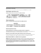
Chapter 6 Command line interface 123 show ports stats pos sonetmediumtbl This command displays statistics (Figure 50) on the SONET medium.
Chapter 6 Command line interface Table 51 Information fields for output of the show ports stats pos sonetmediumtbl command Field Description PORT NUM Port number. MEDIUM TYPE Identifies whether a sonet or sdh signal is used across the interface. TIME ELAPSED Number of seconds, including partial seconds, that have elapsed since the beginning of the current measurement period. If the current interval exceeds the maximum value, the agent will return the maximum value.
Chapter 6 Command line interface 125 Figure 51 show tech command output Passport-8610:5/show/tech General Info SysName SysUpTime SysContact SysLocation 95052 : : : : : Passport-8610 0 day(s), 17:00:58 support@nortelnetworks.
Chapter 6 Command line interface Table 52 Information fields for output of the show tech command Field Description SysName System name. SysUpTime Period for which the system has been active. SysContact Support contact. SysLocation Physical location of the system. Chassis Info Description of the chassis. Chassis Module number. Serial Serial number. HwRev Hardware revision information. NumSlots Number of slots. NumPorts Number of ports.
Chapter 6 Command line interface monitor ports monitor ports monitor ports monitor ports monitor ports monitor ports monitor ports monitor ports [] monitor ports stats stats stats stats stats stats stats stats pos pos pos pos pos pos pos pos 127 lineinterval [] linkstatus [] lqrstatus [] pathcurrent [] pathinterval [] pppiftbl [] sectioncurrent [] sectioninterval stats pos sonetmediumtbl [] Test comma
Chapter 6 Command line interface Using the test commands Note: You must specify a slot and port number with the test commands. Refer to the Reference for the Passport 8000 Series Command Line Interface Switching Operations, Release 3.1 and Reference for the Passport 8000 Series Command Line Interface Routing Operations, Release 3.1 for a complete list of CLI test commands. test hardware Use the test hardware command to run diagnostics on the Passport 8683POS Module.
Chapter 6 Command line interface 129 Note: You must physically inspect the LEDs on the actual Passport 8683POS Module to view the results of these tests. Table 53 describes the parameters and variables for the test led command. Table 53 test led command parameters and variables Parameters and variables Description tx Tests the LED for transmitting data on each port. rx Tests the LED for receiving data on each port. off Tests whether the LEDs go off correctly.
Chapter 6 Command line interface 3 To stop the loopback testing, enter: test stop loopback Figure 53 shows output for the test loopback command. Figure 53 test loopback command output Passport-8610:5/show/test# loopback 10/6 Running an internal loopback test...
Chapter 7 Web management This chapter contains information about the Web management interface available with the Passport 8683POS Module. The Web interface allows you to monitor the Passport 8683POS Module through a World Wide Web browser from anywhere on your network. The Web interface provides many of the same monitoring features as the Device Manager software.
Chapter 7 Web management Figure 54 System page Table 54 describes the fields displayed in the System page.
Chapter 7 Web management 133 Table 54 System page fields Field Description sysDescr System description. sysUpTime Period for which the system has been active. sysContact Support contact. sysName System name. sysLocation Physical location of the system. Authentication Traps Indicates whether traps have been generated for the interface. EnableWebServer Indicates whether the web server has been enabled. EnableAccessPolicy Indicates whether access policy has been enabled.
Chapter 7 Web management Figure 55 System page showing the POS menu To view the current SONET parameters, in the POS menu, click Sonet. The Sonet page opens (Figure 56).
Chapter 7 Web management 135 Figure 56 SONET page Table 55 describes the fields displayed in the SONET page. Table 55 SONET page fields Field Description Index Unique value assigned to each interface. Framing Indicates if framing is enabled or disabled. Section Trace Indicates the integer that the section trace is set to. Signal Label Indicates operational value of Path Signal Label. Clock Source Indicates setting of the clock source. Scramble Indicates operational value of SONET scramble.
Chapter 7 Web management Figure 57 Link page Table 56 describes the fields displayed in the Link page. Table 56 Link page fields Field Description Index Unique value assigned to each interface. Link Config Magic Number If set to enable, selects a random number (“magic number”) used in loopback detection. Link Config Crc Size Indicates if the size of redundancy check field used in PPP framing has been configured. To view the current bridging parameters, in the POS menu, click Bridge.
Chapter 7 Web management 137 Figure 58 Bridge page Table 57 describes the fields displayed in the Bridge page. Table 57 Bridge page fields Field Description Index Unique value assigned to each interface. Bcp Admin Status Indicates the status of bridging. Oper Status Indicates the operational state of bridging. To view the current IP parameters, in the POS menu, click IP. The IP page opens (Figure 59).
Chapter 7 Web management Figure 59 IP page Table 58 describes the fields displayed in the IP page. Table 58 IP page Field Description Index Unique value assigned to each interface. Ipcp Admin Status Indicates the status of IP routing, either enabled or disabled. Oper Status Indicates the operational value of IP link. To view the current IPX parameters, in the POS menu, click IPX. The IPX page opens (Figure 60).
Chapter 7 Web management 139 Figure 60 IPX page Table 59 describes the fields displayed in the IPX page. Table 59 IPX page fields Field Description Index Unique value assigned to each interface. Ipxcp Admin Status Indicates the status of IPX routing, either enabled or disabled. Oper Status Indicates the operational value of IPX link. Net Addr Network address. To view the current Lqr parameters, in the POS menu, click Lqr. The Lqr page opens (Figure 61).
Chapter 7 Web management Figure 61 Lqr page Table 60 describes the fields displayed in the Lqr page. Table 60 Lqr page fields Field Description Index Unique value assigned to each interface. Config Status Status of link quality reporting. Config Interval Link quality reporting interval. To view the current Line parameters, in the POS menu, click Line. The Line page opens (Figure 62).
Chapter 7 Web management 141 Figure 62 Line page Table 61 describes the fields displayed in the Line page. Table 61 Line page fields Field Description Index Unique value assigned to each interface. Config PPP Stp Status of PPP bridging. Local Ip Addr Local Internet Protocol address. Remove IP Addr Remote Internet Protocol address. Config Lqr Threshold Link quality reporting threshold. To view the current Sonet Medium parameters, in the POS menu, click Sonet Medium.
Chapter 7 Web management Figure 63 SONET Medium page Table 62 describes the fields displayed in the SONET Medium page. Table 62 SONET Medium page fields 209564-A Field Description Index Unique value assigned to each interface. Type Signal type, whether sonet or sdh. Time Elapsed Number of seconds that have elapsed since the beginning of the current measurement period. Valid Intervals Number of previous 15-minute intervals for which data was collected.
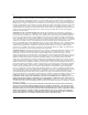
Chapter 7 Web management 143 Statistics Use the Web interface to view the Passport 8683POS Module statistics. Under the Statistics heading in the navigation pane, there are two options: Chassis and Port. Click Port to view the options. Sonet is the last entry in the Port folder. The Sonet heading contains the options shown in Figure 64. Figure 64 Sonet options Click any of the headings to view the relevant statistics. See Figure 65 for an example of PPP Link statistics.
Chapter 7 Web management Figure 65 PPP Link statistics page 209564-A
Appendix A Technical Specifications This appendix lists the technical specifications for the Passport 8683POS Module.
Appendix A Technical Specifications Environmental specifications Operating temperature: 5° to 40° C (41° to 104° F) Storage temperature: -25° to 70° C (-13° to 158° F) Operating humidity: 85% maximum relative humidity, noncondensing Storage humidity: 95% maximum relative humidity, noncondensing Operating altitude 3,000 m (10,000 feet) maximum Storage altitude Up to 9,000 m (30,000 feet) above sea level Free Fall/drop: ISO 4180-s, NSTA 1A Vibration: IEC 68-2-6/34 Shock/bump: IEC 68-2-2
Appendix A Technical Specifications 147 Electromagnetic emissions Meets requirements of: US: FCC, CFR 47, Part 15, Subpart B, Class A Canada: ICES-003, Issue-2, Class A Australia/New Zealand: AS/NZS 3548:1995, Class A Japan: VCCI V-3/97.
Appendix A Technical Specifications 209564-A
Index A clocking 97 AbsoluteValue statistics 80 clock-source command 97 Action field 58 Close button 49 AdminStatus field 57 command line interface 53 alarm statistics 104 config pos command 93 applications, typical 29 config pos info command 98 Apply button 49 Average statistics 80 configuration connecting to a switch fabric module 25 installing MDAs 42 with Device Manager 46 B configuring bridging 62 BCP 63 console port 28 Bridge Control Protocol (BCP, bcp) disabling 96 enabling 62,
Index distance, maximum 31 downloading image 41 E enabling trace messages 92 environmental precautions 35 environmental specifications 146 F info command displaying the image file name 93 last saved ports 94 next-level CLI commands 94 information 100 initial setup 40 initialization 40 Insert button 49 Insert Trap Receiver dialog box 73 installing a module 37 failover 23 interface options 146 far end line interval statistics 107 far end path interval statistics 109 Interface tab graphic 56 tab i
Index link quality interval 96 link quality reporting statistics 115 151 N name field 57 link quality threshold 96 LinkConfigMagicNumber field 65 linktrap command 94 LinkTrap field 58 lock command 94 Locked field 58 locking a port 58 O off command 129 onfiguration procedures 54 OperDuplex field 58 OperSpeed field 58 OperStatus field 57 loopback 75, 127 loopback detection 65, 96 lqr-interval command 96 lqr-status command 96 lqr-threshold command 96 M magic-number command 96 management 25, 46 Maximum st
Index POS Graph statistics tab 81 SDH 30, 61, 97 POS Interface, in Device Manager 49 section interval statistics 121 POS PPP tab graphic 64 tab items 65 section statistics 120 POS SONET tab graphic 60 tab items 61 Section tab 85 section-trace command 97 security 97 show ports info pos command 100 POS Statistics tab 83 show ports stats pos activealarms command 104 PPP 29, 30, 31, 33 show ports stats pos felinecurrent command 105 PPP configuration commands 95, 97 show ports stats pos feline
Index support, Nortel Networks 21 switching 24 T tagged-frames-discard command 94 153 U untagged-frames-discard command 94 V VendorDescr field 57 tagging 94 tagging frames 94 technical publications 20 Y yellow command 129 technical specifications 145 technical support 21 test hardware command 128 test led command 128 test mode 75, 127 testing 128 text conventions 18 The 84 timing 97 transmission distance 31 transmission rates 30 trap log 71 Trap Receivers tab 72 traps 71 troubleshooting CPU failover
Index 209564-A