
User's Manual
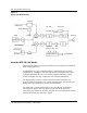
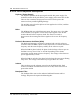
Table Of Contents
- Publication history
- BTR 38 GHz Release 1.2
- Grounding and Surge Protection
- List of terms

BTR 38 GHz Release 1.2 1-3
BTR 38 GHz Installation Guide
1. The BTR transceiver’s input coaxial cable carries the IF signals and the
power supply to the diplexer. The diplexer distributes the power to the
power supply unit and interfaces with the mixer for the IF signals.
2. The 450-650 MHz transmit IF signals enter the mixer which upconverts
the signals to the 39.45 to 39.65 GHz band for the transmit path. The
received RF band is downconverted to a receive signal in the 50-250 MHz
range.
3. The local oscillator (LO) provides local oscillator signal to the mixer. The
LO uses a phase-locked dielectric resonance oscillator (DRO) with an
oven controlled crystal oscillator (OCXO).
4. The bandpass filters remove the undesired sideband signals, in both the
transmit and receive paths.
5. The upconverted signal is fed into the power amplifier which provides the
required gain to the microwave signals. The power amplifier output is
connected to the antenna through the antenna mounting flange.
6. The received RF simultaneously passes through the antenna mounting
flange, where the pass band is filtered and amplified by the Low Noise
Amplifier (LNA). The signal is fed into the mixer path.
7. The downconverted signal is fed into the IF amplifier which provides the
required gain to the IF signals. The IF amplifier’s output is connected to
the IF (RX) output port.
8. The remote monitor unit is monitoring the BTR 38 GHz working status,
(temperature, RF output power, power supply voltage and local oscillator
status).
There are five connectors on the outside of the transceiver case:
• The IF (TX) power supply input uses a Type N female jack
• The IF (RX) output uses a Type N female jack
• Telemetry connector uses a 6 pin military style connector
• Test Port (2) use female SMA jack