
User's Manual
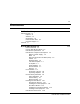
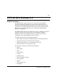
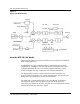
Table Of Contents
- Publication history
- BTR 38 GHz Release 1.2
- Grounding and Surge Protection
- List of terms

1-6 BTR 38 GHz Release 1.2
411-1333-204.01.02 Preliminary March 1999
BTR 38 GHz Component Descriptions
Diplexer / Power Supply
The diplexer separates the IF input signals and the DC power supply. The
isolation between the IF path and the power supply path is more than 35 dB.
There is also a transient voltage protector on the board to protect the
transceiver from possible lightning damage.
The 48 VDC power from the diplexer is first regulated to 12 VDC, and then
sent to all the modules.
Mixer
The BTR 38 GHz uses a third harmonic mixer. The mixer uses a 13.0 GHz
local oscillator (LO) signal to convert the IF input signals to the 39.450-
39.650 GHz microwave frequency band. The same LO is used to
downconvert the incoming microwave signals to the receive IF frequency
band.
Dielectric Resonance Oscillator (DRO)
The Dielectric Resonance Oscillator is equipped with a OCXO reference
oscillator. When the DRO is phase-locked, it provides a 13.0 GHz microwave
frequency with the same frequency stability as the reference crystal.
When the DRO is phase-locked, the phase-locked voltage at the test port on
the DRO can vary from 3 VDC to 10 VDC depending on the chassis
temperature and the input reference frequency. The voltage at the alarm test
port is approximately 5 VDC.
When the DRO is unlocked, the phase-locked voltage becomes an oscillating
ramp wave. The voltage at the alarm test port goes down to 0 VDC.
Isolator
Three isolators provide adequate return loss in the BTR 38 GHz. Each
isolator’s maximum forward insertion loss is 0.5 dB, and its return loss is
greater than 18 dB.
Bandpass Filter
The bandpass filter removes the undesired sideband elements and LO
leakage, and passes the required sideband signals.