
User's Manual
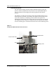
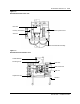
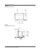
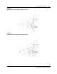
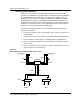
Table Of Contents
- Publication history
- BTR 38 GHz Release 1.2
- Grounding and Surge Protection
- List of terms

BTR 38 GHz Release 1.2 1-11
BTR 38 GHz Installation Guide
Installing the Tower Equipment
Install the BTR 38 GHz microwave transceiver as follows:
The radio mounting saddle has no paint on the inside surface in order to
provide a grounding.
1. Ensure that the radio mounting surface on the pole is free of paint to
provide a grounding.
2. Mount the BTR 38 GHz to a stable pole using the supplied mounting
brackets. The mounting brackets accommodate poles with outside
diameters from 2.5" to 4.5". See Figures 1-11, 1-12, 1-15, 1-16, and 1-21.
3. There are four 1/2” 13 UNC threaded rods, along with four hex head nuts
and flat and lock washers. Thread the rod into the saddle bracket, then
tighten with the nut. The flat washer is against the exterior of the bracket,
followed by the lock washer and then the nut.
4. Ensure connectors are facing down.
5. Install the BTR 38 GHz so that the fin array (heat sink) is positioned away
from external barriers to allow heat dissipation through natural convection
and radiation. See Figures 1-11, 1-17, 1-18, and 1-21.
The BTR 38 GHz requires 48 VDC power supply unit.
6. Connect the TX/power coaxial cable from the RPE 9000’s TX female N-
Type connector to the BTR’s N-type IF and PS IN port.
7. Connect the RF coaxial cable from the RPE 9000’s RX female N-Type
connector to the BTR’s N-type IF OUT port.
8. Connect the telemetry cable from the BTR 38 GHz to the RPE 9000’s
telemetry connector. There is a 300 baud modem connection between the
BTR 38 GHz, the RPE 9000 and the RSM 9016.
See Figures 1-11 and 1-17.
9. Seal all connections using Coax-Seal®, cold shrink or hot shrink
tubing.
10. Ground all RF cables at the recommended spacing intervals. (Refer to
tower and cable manufacturers’ specifications).
11. Ensure that all feed lines are securely attached to the support structure.
Plan for drip (service) loops on all cables.
12. The BTR 38 GHz has a vertical range of motion of +7° over and -23°
under the horizon, as shown in Figures 1-13 and 1-14.
13. Refer to Outline and Installation Drawing # PO 883482 and the Reunion
Redundancy Switching Matrix Installation Guide, 411-1313-201.
Caution
Do not turn on the power supply until the installation is
complete.
After you install the equipment, check the cable connections.