
User's Manual
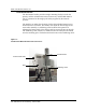
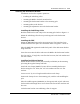
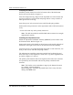
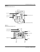
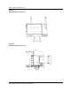
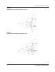
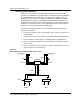
Table Of Contents
- Publication history
- BTR 38 GHz Release 1.2
- Grounding and Surge Protection
- List of terms

1-14 BTR 38 GHz Release 1.2
411-1333-204.01.02 Preliminary March 1999
Installing the Radios
Install the primary transceiver on the left exterior side of the dual mount
bracket (front view). Refer to Figure 1-3.
Insert the compression lug, adjacent to the unpainted area of the bracket unit,
and secure with 3/8" screw and flat and spring washers. Crimp a number 6
AWG ground wire to the lug.
Insert the top two 3/8" screws and secure with flat and spring washers.
Position the back-up transceiver on the right interior side of the bracket (front
view).
Secure it the same way as the primary transceiver.
Note: The dual mount bracket with the RPE and two transceivers weighs
approximately 100 lbs.
Installing the Adjustment Arm
Mount the adjustment arm/handle assembly (P0888357) to the bottom of the
dual mount bracket. Refer to Figure 1-3.
Position the left side of the handle on the left interior side and the right side of
the handle on the right exterior side of the dual mount bracket assembly.
Screw four 3/8" by 7/8" long bolts through the mount to each transceiver, two
bolts per side. Secure with flat and spring washers.
The adjustment arm with the transceivers attached can be adjusted up and
down vertically. It can be adjusted 23° down and 7° up, that is angled down or
up. Refer to Figures 1-7 and 1-8.
The polarity of the transmit and receive signals at the transceivers’ antennas
are separated by 90°. Horizontal and vertical polarity is marked on the
antennas.
Note: The bracket can accommodate a range in pole diameter between
2.5" and 4.5" (outside diameter).
Wind loading spec: maximum 45 pounds lateral force in any direction
during a 100 MPH wind