Nortel CallPilot Troubleshooting Reference Guide NN44200-700 .
Document status: Standard Document version: 01.05 Document date: 26 June 2007 Copyright © 2007, Nortel Networks All Rights Reserved. Sourced in Canada The information in this document is subject to change without notice. The statements, configurations, technical data, and recommendations in this document are believed to be accurate and reliable, but are presented without express or implied warranty. Users must take full responsibility for their applications of any products specified in this document.
QUICKTIME is a trademark of Apple Computer, Inc. RADISYS is a trademark of Radisys Corporation. ROLM is a trademark of Siemens ROLM Communications Inc. SLR4, SLR5, and TANDBERG are trademarks of Tandberg Data ASA. SONY is a trademark of Sony Corporation. SYBASE is a trademark of Sybase, Inc. TEAC is a trademark of TEAC Corporation. US ROBOTICS, the US ROBOTICS logo, and SPORTSTER are trademarks of US Robotics. WINZIP is a trademark of Nico Mark Computing, Inc. XEON is a trademark of Intel, Inc.
Publication History June 2007 CallPilot 5.0, Standard 01.05 of the Troubleshooting Reference Guide is updated as per the CR Q01665596. May 2007 CallPilot 5.0, Standard 01.04 of the Troubleshooting Reference Guide is issued for general release. April 2007 CallPilot 5.0, Standard 01.03 of the Troubleshooting Reference Guide is issued for general release. April 2007 CallPilot 5.0, Standard 01.02 of the Troubleshooting Reference Guide is issued for general release. March 2007 CallPilot 5.0, Standard 01.
Publication History Nortel CallPilot Troubleshooting Reference Guide NN44200-700 01.05 Standard 5.0 26 June 2007 Copyright © 2007, Nortel Networks .
Contents Chapter 1 How to get help 9 Getting Help from the Nortel Web site 9 Getting Help over the phone from a Nortel Solutions Center 9 Getting Help from a specialist by using an Express Routing Code Getting Help through a Nortel distributor or reseller 10 10 Chapter 2 Overview General 11 Reference documents 11 12 Chapter 3 Hardware troubleshooting 13 201i server 13 703t server 17 1002rp server 28 1005r server 41 600r server 50 Chapter 4 Network troubleshooting 59 Check cabling 59 Check end
Contents RAS dial-up required to establish RDC 124 Double-Hop remote control 124 Transferring files in Remote Desktop Connection sessions 126 Terminal Server Maximum Connections Exceeded error 126 Disconnecting the Remote Desktop Connection session 127 View or disconnect concurrent or previous stale sessions 127 Troubleshooting tips 128 Chapter 6 Application troubleshooting 131 Chapter 7 Meridian Mail to CallPilot migration troubleshoot ing 143 General 143 Symptom 1: Error reading tape during data tran
Chapter 1 How to get help This section explains how to get help for Nortel products and services. Getting Help from the Nortel Web site The best way to get technical support for Nortel products is from the Nortel Technical Support Web site: http://www.nortel.com/support This site provides quick access to software, documentation, bulletins, and tools to address issues with Nortel products.
Chapter 1 How to get help Getting Help from a specialist by using an Express Routing Code To access some Nortel Technical Solutions Centers, you can use an Express Routing Code (ERC) to quickly route your call to a specialist in your Nortel product or service. To locate the ERC for your product or service, go to: http://www.nortel.
Chapter 2 Overview In this chapter "General" (page 11) "Reference documents" (page 12) General This troubleshooting reference guide describes symptoms that can appear on all CallPilot server platforms, and provides step-by-step troubleshooting procedures. The troubleshooting procedures can be slightly different for different CallPilot releases. Each troubleshooting area contains symptom tables outlining basic checks that include diagnostics and resolutions for each check.
Chapter 2 Overview Reference documents Nortel CallPilot Troubleshooting Reference Guide NN44200-700 01.05 Standard 5.0 26 June 2007 Copyright © 2007, Nortel Networks .
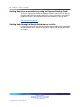
Chapter 3 Hardware troubleshooting In this chapter "201i server" (page 13) "703t server" (page 17) "1002rp server" (page 28) "1005r server" (page 41) "600r" (page 50) 201i server System troubleshooting Trouble Action The system emits beep codes. The state of the PC chip set is associated with beep codes. Some codes indicate relatively harmless failure situations that allow you to start up the CallPilot server, even though the system is not fully functional unless you solve the trouble.
Chapter 3 Hardware troubleshooting Trouble Action The HEX display is not on at startup. The system can be in a catastrophic failure state. • The power supplies have malfunctioned. • The 8051 system controller failed. The 8051 system controller and the HEX display work together and perform a quick system hardware test before the operating system starts up. Refer to the 201i Server Maintenance and Diagnostics document (NN44200-705) for information on interpreting the HEX display.
201i server 15 SCSI peripheral troubleshooting Trouble The system does not start from the CD-ROM. Action Note: The 201i server does not support this feature at this time. The system displays error messages while the operating system is installed from the CD-ROM. Ensure that the most recent version of the CD-ROM SCSI driver is installed on your system. The CD-ROM drive is not shown in the operating system.Errors occur during CD-ROM or tape operation.
Chapter 3 Hardware troubleshooting Trouble Action • The other two LEDs indicate the IDE (I) and SCSI (S) activity of the following devices: — IDE (I) — SCSI (S) If the Ethernet link LEDs are not on, check the Ethernet cabling. Note: The link LEDs blink to indicate network activity. The CallPilot Nortel server subnet does not work when the server is connected to a large Meridian 1 system. The 201i server uses two auto-negotiating Ethernet network interface cards (NIC).
703t server 17 703t server Server LEDs The LEDs indicate the state of your server and can help you troubleshoot startup problems. The following tables provide useful information on the external and internal LEDs. External LEDs Description Information MPB96 DS30 link LEDs (three green LEDs located on the card bracket and visible from the back of the server) When these LEDs are on, all three DS30 connections are working properly and the cables are connected correctly.
Chapter 3 Hardware troubleshooting Description Information started and the CallPilot diagnostic screen has appeared, then the MPB96 board is defective or the DSP and NTBus drivers do not function properly. • RAID controller LEDs The CTbus FPGA Done LED (the farthest from the card I/O bracket) works in tandem with the DSP FPGA Done LED and turns on and off at the same time. The RAID controller has one red LED and eight small LEDs at the back.
703t server System troubleshooting Trouble Action The system does not boot and appears dead. The system does not emit any beeps. The fans do not turn. Verify that the power cord is properly plugged in the power outlet. Check if other equipment plugged in the same power outlet works. Note: If the fans are turning, but the system emits no beeps, verify that: The system does not start, but emits beeps. • The monitor is turned on.
Chapter 3 Hardware troubleshooting Trouble Action The system beeps and displays information on the screen, but the operating system does not start up. This is a typical RAID beep. One of the following condition is present: • One cable or both cables from the hard drives is disconnected or improperly connected. • One or both drives is faulty. In special situations, this symptom indicates that the NVRAM contents and the drive configuration were lost.
703t server 21 Trouble Action The system starts up and, immediately after the video information string displays an error message such as the following: PCI vendor ID does not match the Device ID. This is not a critical error message. The system board displays an error message in red and does not start up. This is a Management Controller failure. This failure is serious and occurs because a board in the system was replaced, but the server was not shut down and unplugged. In CallPilot 3.
Chapter 3 Hardware troubleshooting RAID troubleshooting Trouble Action The system boots and generates beeps. One or more logical drives is in critical mode (one of the drives is in FAIL condition). Rebuild the drives. If the drive rebuilding is unsuccessful, replace the drives. The system does not detect the RAID card. The system detects the RAID card, does not boot, and attempts to boot from the network. The RAID card can be defective. Check the LEDs on the back of the card.
MPB96 board troubleshooting Trouble Action The system does not rebuild a new drive installed to replace a faulty drive. When you replace a defective drive, the new drive must be larger than the original drive. In this case, the system rebuilds the new drive. 23 However, if the new drive is smaller than the original drive, it must not be smaller by more than 1 GB. If the new drive is smaller than the original drive by less than 1 Gbyte, the GBWay setting in the Adapter properties is disabled.
Chapter 3 Hardware troubleshooting • CallPilot 2.0x: version 1.0, May 2003 The CallPilot system contains two types of FPGA firmware. FPGA firmware Description PCI FPGA The version format of the PCI FPGA firmware follows an internal naming convention established to facilitate the tracking of the card release. The tool displays the version in hexadecimal format as follows: xPxx yyaNN, where • x must be 0 • P represents the PCI slot: 8 for 3.
MPB96 board troubleshooting 25 4 Select the board number; that is, the slot in which the board is installed (for example, 4 for a 703t system connected to a Meridian 1 switch). 5 Select option 5 (500 ms polling time) Result: The system launches the nbhaltswmon.exe utility and displays a screen containing all the MPB96 registers. The status of the registers indicates the status of the card. You can interpret the card status by reading the bit significance in the MPB96 Unified document.
Chapter 3 Hardware troubleshooting The dbg128.exe is an extremely powerful tool designed for debugging the MPB96 board. It can replace all the preceding tools and provide full control over all the MPB96 registers and memory. Windows and CallPilot hardware troubleshooting Trouble symptom Action The system beeps, but seems to be running properly and taking calls. This is a RAID card beep indicating that one of the drives does not function properly. Do not shut down the system.
MPB96 board troubleshooting Trouble symptom Action The system starts up, but attempts to boot to the operating system from the network. Shut down the server and open the lid. Turn on the server and check the RAID controller LEDs. If more than four LEDs stay on after the startup, then the problem is related to the RAID controller. • Shut down the system. • Reseat the RAID controller. • Reboot the system.
Chapter 3 Hardware troubleshooting Trouble symptom Action The system detects the MPB96 board only partially, and Configuration Wizard does not run. The MPB96 board is configured incorrectly from the clocking point of view. The system detects the MPB96 board, but does not load correctly the DSP information at startup. The cache.bin file in the D:\nortel\hardware\dsp\c52\ folder is corrupted. Contact your Nortel support representative for assistance.
1002rp server Description Information Network interface card (NIC) LEDs Each NIC has two LEDs: • The upper LED shows that the network cable is connected. • The lower LED blinks to indicate data transfer. 29 Internal LEDs Description Information MPB16-4 board LED The five LEDs at the top of the MPB16-4 board are visible through the grill at the back of the server. • The four DSP Power On LEDs come on when the CallPilot drivers are loaded, right before the diagnostic screen starts.
Chapter 3 Hardware troubleshooting Description Information started and the CallPilot diagnostic screen has appeared, then the MPB96 board is defective or the DSP and NTBus drivers do not function properly. • RAID controller LEDs The CTbus FPGA Done LED (the farthest from the card I/O bracket) works in tandem with the DSP FPGA Done LED and turns on and off at the same time. The RAID card has one red LED and eight small LEDs on the back.
1002rp server 31 Beep count Message Description 7 Processor Exception Interrupt Error The CPU on the processor board generated an exception interrupt. 8 Display Memory Read/Write Error The system video adapter is missing, or its memory is faulty. Note: This error is not fatal. 9 ROM Checksum Error The ROM checksum value does not match the value encoded in the BIOS. System troubleshooting Trouble symptom Action The system appears dead.
Chapter 3 Hardware troubleshooting Trouble symptom Action The system does not start, but emits beeps. No information is displayed on screen. Identify the type of beeps that your system emitted. • The system board beeps are usually short; their pattern is identified in the 1002rp Server Maintenance and Diagnostics guide (NN44200-300). The system board beeps are usually not associated with information displayed on screen.
1002rp server Trouble symptom 33 Action Ctrl+M utility at startup, and ensure that the RAID setup matches the settings indicated in the 1002rp Server Maintenance and Diagnostics guide. The system boots to the operating system and beeps intermittently. ATTENTION Do not reboot your system! This symptom typically indicates a RAID problem: one of the hard drives is in critical condition. Rebuild the drives as soon as your system boots to the operating system.
Chapter 3 Hardware troubleshooting Trouble symptom Action • If the system boots correctly, consider replacing the PCI backplane because it is only partially functional. • If the system does not boot correctly, replace the PCI backplane. Note: Each set of four slots is controlled by a different PCI bridge.
1002rp server Trouble symptom Action The Ethernet controllers are enabled and detected, but the ping command fails when used to check network resources. • Open a DOS command prompt window. • Type ipconfig /all. The software feature key adapter (dongle) is installed properly, but CallPilot cannot detect it. The ipconfig command displays the MAC addresses. If the MAC addresses are missing or have the same value, then they are not programmed. Return the SBC card to the factory.
Chapter 3 Hardware troubleshooting Trouble Action RAID troubleshooting Trouble Action The system boots but emits beeps. One or more logical drives are in critical mode (one of the drives is in FAIL condition). Rebuild the drives. If the drive rebuilding is unsuccessful, replace the drive. The system does not detect the RAID card. The RAID card can be defective. Check the LEDs on the back of the card. If more than four LEDs are lit, the RAID card or the PCI backplane is faulty.
1002rp server Trouble Action The system does not rebuild a new drive installed to replace a faulty drive. When you replace a defective drive, the new drive must be larger than the original drive. In this case, the system rebuilds the new drive. 37 However, if the new drive is smaller than the original drive, it must not be smaller by more than 1 Gbyte. If the new drive is smaller than the original drive by less than 1 Gbyte, the GBWay setting in the Adapter properties is disabled.
Chapter 3 Hardware troubleshooting MPB16-4 board troubleshooting Trouble Action The CallPilot Diagnostics tool reports that all or some of the DSPs have failed. Ensure that the release of your board is 05 or later. CallPilot starts up, but voice services are not available. You have more than one MPB16-4 board on your system. Ensure that the DS30X cable is connected to the correct MPB16-4 board. CallPilot works, but the voice quality is low—T1/SMDI configurations only.
1002rp server 39 Windows and CallPilot hardware troubleshooting Trouble Action The system beeps but otherwise seems to be running properly and taking calls. This is a RAID card beep indicating that one of the drives does not function properly. Do not shut down the system. • Open the MegaRAID utility and check which drive is marked as Dead. • Rebuild the drive marked as Dead. • If the drive rebuild is not successful, ensure that the other drive is functioning correctly.
Chapter 3 Hardware troubleshooting Trouble Action All DSP diagnostics fail at system startup. Ensure that the MPB16-4 boards are release 5 or later. Ensure that the PCI backplane does not have Intel PCI bridge chips. Shut down the server and open the lid. Power up the server and check if the PCI LED on the MPB16-4 board is still on after startup. If the LED still stays on, shut down the server and replace the board.
1005r server Trouble Action The system ELAN or CLAN are not working, even though they are detected and displayed in the operating system control panel. Enable the NIC controllers in the BIOS, and ensure that the BIOS settings are correct. The hard drives have intermittent problems and media errors. 41 Open a DOS command prompt window and type ipconfig /all. The ipconfig command displays the MAC addresses. If the MAC addresses are missing or are the same, the MAC addresses are not programmed.
Chapter 3 Hardware troubleshooting Server LEDs The LEDs indicate the state of your server and can help you troubleshoot startup problems. The following tables provide useful information about the external and internal LEDs. Front panel LEDs LED Functional Description CRT A critical system fault is an error or event that has a fatal system impact. The system cannot continue to operate. MJR A major system fault is an error or event that has a discernible impact on system operation.
1005r server 43 Internal LEDs Description Information MPB96 board LEDs The three red LEDs at the top of the MPB96 board are visible through the grill at the back of the server. • The PCI FPGA Done LED (the closest to the card I/O bracket) comes on at startup and turns off immediately. This indicates that the board works properly and was detected correctly by the system. If this LED stays on after the startup, the card is defective and must be replaced.
Chapter 3 Hardware troubleshooting BIOS error messages appear on the video monitor. Refer to the following table for a description of the messages. Error message Description GA20 Error An error occurred with Gate A20 when switching to protected mode during the memory test. Pri Master HDD Error The system could not read the sector from the corresponding drive.
1005r server 45 Memory Size Decreased The memory size has decreased since the last boot. If you have not removed any memory, then the memory may be faulty. Memory Size Increased The memory size has increased since the last boot. If you have not added any memory, there is a problem with the system. Memory Size Changed The memory size has changed since the last boot. If you did not add or remove any memory, then the memory may be faulty.
Chapter 3 Hardware troubleshooting The system boots but PCI errors appear or fill the screen. Ensure the PCI raiser assembly is plugged in correctly, aligned, and firmly pressed into the slot. You must complete the reseating with the server out of the rack and on a solid surface. Ensure the power cable is plugged in. The system boots, but a blue screen appears. Ensure the PCI raiser assembly is plugged in correctly, aligned, and firmly pressed into the slot.
1005r server 47 8. Boot into service. During startup, a message indicates that the System Event Log is full and the log must be cleared. This is an unusual situation and appears only if the server was booted many times. View the log before clearing it. See the 1005r Hardware Maintenance and Diagnostics guide NN44200-704 for viewing and clearing the System Event Log. After startup, the Intel Server Manager reports that one of the processors is disabled. This causes the system processes to slow down. 1.
Chapter 3 Hardware troubleshooting The system boots but one of the drive LEDs on the front panel is amber. A drive fails and the replacement does not rebuild. The RAID is split, or one of the drives is faulty or offline. Replace or rebuild the drive. No action is required if this is due to a voluntary RAID split. The RAID card settings are incorrect. The coercion algorithm is not set to 1 GB.
1005r server The system displays a blue screen with the following message: Hardware Malfunction, please contact your H/W vendor. The system does not take calls. Ensure the MPB96 board is release 5 or later. All DSP diagnostics fail at system startup. Shut down the server and open the lid. Turn on the server and check if the PCI LED on the MPB96 board is still on after startup. If the LED is still on, then shut down the server, reseat the board, and then turn on the server again.
Chapter 3 Hardware troubleshooting The system detects the MPB96 board only partially, and Configuration Wizard does not run. The MPB96 board is configured incorrectly from the clocking point of view. Contact your Nortel support representative for assistance. The system detects the MPB96 board, but does not correctly load the DSP information at startup. The cache.bin file in the D:\nortel\hardware\dsp\c52\ folder is corrupted. Rerun the Configuration Wizard to reflash the DSPs.
600r server MNR A minor system fault is an error or event that has little impact on system operation. The system continues to operate. PWR A power supply fault indicates that one of the power supplies is not providing power. The MJR LED is also lit.
Chapter 3 Hardware troubleshooting Internal LEDs Description Information MPB96 board LEDs The three red LEDs at the top of the MPB96 board are visible through the grill at the back of the server. • The PCI FPGA Done LED (the closest to the card I/O bracket) comes on at startup and turns off immediately. This indicates that the board works properly and was detected correctly by the system. If this LED stays on after the startup, the card is defective and must be replaced.
600r server 53 BIOS error messages When a recoverable error occurs during the POST, the BIOS displays an error message describing the problem. BIOS error messages appear on the video monitor. Refer to the following table for a description of the messages. Error message Description GA20 Error An error occurred with Gate A20 when switching to protected mode during the memory test. Pri Master HDD Error The system could not read the sector from the corresponding drive.
Chapter 3 Hardware troubleshooting KB/Interface Error The keyboard interface test failed. Memory Size Decreased The memory size has decreased since the last boot. If you have not removed any memory, then the memory may be faulty. Memory Size Increased The memory size has increased since the last boot. If you have not added any memory, there is a problem with the system. Memory Size Changed The memory size has changed since the last boot.
600r server 55 The system boots but a red CRT LED and an amber PWR LED appears. One power supply is faulty, or the AC cable is unplugged (or faulty). The system boots but PCI errors appear or fill the screen. Ensure the PCI raiser assembly is plugged in correctly, aligned, and firmly pressed into the slot. You must complete the reseating with the server out of the rack and on a solid surface. Ensure the power cable is plugged in. The system boots, but a blue screen appears.
Chapter 3 Hardware troubleshooting Ensure the SCSI tape drive has the external SCSI terminator installed. The tape drive is plugged in correctly, but the system experiences errors. (The drive cannot be re-tensioned or go offline randomly). The tape drive may have been plugged into the RAID external SCSI adaptor instead of the SCSI adaptor. Plug the tape into the correct connector at the back of the server. For instructions, see the 600r Server Hardware Installation Guide (NN44200-307).
600r server 57 Dongle troubleshooting Trouble Action The dongle is plugged into the USB slot and is detected in the device manager but CallPilot does not recognize it. Ensure the dongle is in USB slot 0, and not in slot 1 or 2. The dongle is plugged into USB slot 0 but is not visible in the device manager. CallPilot also does not detect it. The dongle holder is not plugged in correctly, or it is defective. Replace it and keep the button. Also, ensure the button is not installed backward.
Chapter 3 Hardware troubleshooting these files and reboot the system. If the PCI LED still stays on, then the MPB96 board is defective and must be replaced. The system starts up, but attempts to boot to the operating system from the network. The RAID card was not detected due to improper seating during PCI assembly. Remove the system from the rack and place it on a table. Re-seat the PCI assembly by securely pushing it into place. Ensure the slots and studs at the back are properly aligned.
Chapter 4 Network troubleshooting In this chapter "Check cabling" (page 59) "Check end-to-end connectivity" (page 59) "Check network adapters and driver installation" (page 59) "Check TCP/IP configuration" (page 60) "Test the TCP/IP" (page 82) "Check event logs" (page 83) Check cabling Ensure that the link LEDs at both ends of each Ethernet cable are on. If the link LEDs are not on, then ensure that the cross-over cables are not being used in error. Try different cables if the link LEDs do not come on.
Chapter 4 Network troubleshooting b. Double-click System. c. Click the Hardware tab. d. Click Device Manager. 2 Expand the Network Adapters tree by clicking the plus sign (+) to the left of this device entry. Result: Two Ethernet adapters are displayed under Network Adapters. 3 Right-click the first network adapter, and then click Properties on the shortcut menu. Result: The network adapter Properties dialog box appears.
Check TCP/IP configuration 2 Right-click CLAN, and then click Status on the shortcut menu. Result:The following dialog box appears. 3 Click the Support tab. Nortel CallPilot Troubleshooting Reference Guide NN44200-700 01.05 Standard 5.0 26 June 2007 Copyright © 2007, Nortel Networks .
Chapter 4 Network troubleshooting 4 Click Details. Result:The following box appears. 5 Click Close. 6 Click Repair on the network adapter status dialog box Result:The following dialog box appears. Nortel CallPilot Troubleshooting Reference Guide NN44200-700 01.05 Standard 5.0 26 June 2007 Copyright © 2007, Nortel Networks .
Check TCP/IP configuration 7 Click OK (this error is normal). 8 Click the General tab of the network adapter status dialog box, and then click Properties. Result:The following dialog box appears. Nortel CallPilot Troubleshooting Reference Guide NN44200-700 01.05 Standard 5.0 26 June 2007 Copyright © 2007, Nortel Networks .
Chapter 4 Network troubleshooting 9 Click the Internet Protocol (TCP/IP) entry to select it. Nortel CallPilot Troubleshooting Reference Guide NN44200-700 01.05 Standard 5.0 26 June 2007 Copyright © 2007, Nortel Networks .
Check TCP/IP configuration 10 Click Properties. Result:The following dialog box appears. Nortel CallPilot Troubleshooting Reference Guide NN44200-700 01.05 Standard 5.0 26 June 2007 Copyright © 2007, Nortel Networks .
Chapter 4 Network troubleshooting 11 Click Advanced. Result:The following dialog box appears. Nortel CallPilot Troubleshooting Reference Guide NN44200-700 01.05 Standard 5.0 26 June 2007 Copyright © 2007, Nortel Networks .
Check TCP/IP configuration 12 Click the DNS tab. Check that the settings are correct for your private network. Nortel CallPilot Troubleshooting Reference Guide NN44200-700 01.05 Standard 5.0 26 June 2007 Copyright © 2007, Nortel Networks .
Chapter 4 Network troubleshooting 13 Click the WINS tab. Nortel CallPilot Troubleshooting Reference Guide NN44200-700 01.05 Standard 5.0 26 June 2007 Copyright © 2007, Nortel Networks .
Check TCP/IP configuration Note: WINS IP addresses must be entered for your private network. 14 Click the Options tab. Check that the settings are correct for your private network. Nortel CallPilot Troubleshooting Reference Guide NN44200-700 01.05 Standard 5.0 26 June 2007 Copyright © 2007, Nortel Networks .
Chapter 4 Network troubleshooting 15 Click Properties on the Options tab to display information about TCP/IP filtering. Check that the settings are correct for your private network. Nortel CallPilot Troubleshooting Reference Guide NN44200-700 01.05 Standard 5.0 26 June 2007 Copyright © 2007, Nortel Networks .
Check TCP/IP configuration 16 Click Cancel to close the TCP/IP filtering dialog box. 17 Click Cancel to close the Advanced TCP/IP Settings dialog box. 18 Click the Authentication tab in the CLAN Properties dialog box. Nortel CallPilot Troubleshooting Reference Guide NN44200-700 01.05 Standard 5.0 26 June 2007 Copyright © 2007, Nortel Networks .
Chapter 4 Network troubleshooting 19 Click the Advanced tab in the CLAN Properties dialog box. Nortel CallPilot Troubleshooting Reference Guide NN44200-700 01.05 Standard 5.0 26 June 2007 Copyright © 2007, Nortel Networks .
Check TCP/IP configuration 20 Click the General tab in the CLAN Properties dialog box. Nortel CallPilot Troubleshooting Reference Guide NN44200-700 01.05 Standard 5.0 26 June 2007 Copyright © 2007, Nortel Networks .
Chapter 4 Network troubleshooting 21 Click Configure. Result: The Ethernet adapter Properties dialog box appears. Nortel CallPilot Troubleshooting Reference Guide NN44200-700 01.05 Standard 5.0 26 June 2007 Copyright © 2007, Nortel Networks .
Check TCP/IP configuration 22 Click the Advanced tab. Nortel CallPilot Troubleshooting Reference Guide NN44200-700 01.05 Standard 5.0 26 June 2007 Copyright © 2007, Nortel Networks .
Chapter 4 Network troubleshooting The default property values in the Advanced tab differ according to the link and CallPilot platform used. The following tables provide the default values for different cases. Note: Other values can work and can be acceptable under certain circumstances.
Check TCP/IP configuration Property Value Speed AutoDetect Transmit Control Blocks 8 77 703t Intel PRO/1000 MT network controller (CLAN) default advanced property values Property Value Fast Transmit Completion On Flow Control Both on Link Speed & Duplex AutoDetect Locally Administer ed Address Not Present Number of Coalesce Buffers 128 Number of Receive Buffers 256 Number of Transm it Descriptors 256 Offload Receive IP checksum On Offload Receive TSP checksum On Offload TCP Segme
Chapter 4 Network troubleshooting Property Value Flow Control Settings Off IP Security Enabled Large Send Enabled Link Speed & Duplex AutoDetect Locally Administer ed Address Not Present Receive Buffers 48 Security Associatio ns 64 Smart Power Down Enabled Transmit Control Blocks 16 1002rp Intel 8255x-based PCI Ethernet adapter (10/100) [CLAN and ELAN] default advanced property values Property Value 802.
Check TCP/IP configuration Property Value Smart Power Down Disabled Transmit Control Blocks 16 79 1005r Intel PRO/1000 MT Dual port Ethernet adaptor - default advanced property values Property Value Adaptive Inter-Frame Spacing Enabled Enable PME OS controlled Express Teaming Teaming disabled Flow Control Generate and Respond Interrupt Moderation Rate Adaptive Jumbo Frames Disabled Link Speed and Duplex Auto Detect Locally Administered Address Not present Log Link State Event Enab
Chapter 4 Network troubleshooting 23 Jumbo Frames Disabled Link Speed and Duplex Auto detect Locally Administered Address Not present Log Link State Event Enabled Offload Receive IP Checksum On Offload Receive TCP Checksum On Offload TCP Segmentation On Offload Transmit IP Checksum On Offload Transmit TCP Checksum On Qos Packet Tagging Disabled Receive Descriptors 256 Smart Power Down Hardware default Transmit Descriptors 256 Wake on Link Settings Disabled Wake on Settings
Check TCP/IP configuration 24 Click the Resources tab.Check that the settings are correct for your private network. Nortel CallPilot Troubleshooting Reference Guide NN44200-700 01.05 Standard 5.0 26 June 2007 Copyright © 2007, Nortel Networks .
Chapter 4 Network troubleshooting 25 Perform steps 2 through 22 for the ELAN adapter. —End— Test the TCP/IP Step Action 1 Open a Command Prompt window. 2 Type ipconfig/all to display the network settings. Nortel CallPilot Troubleshooting Reference Guide NN44200-700 01.05 Standard 5.0 26 June 2007 Copyright © 2007, Nortel Networks .
Check event logs 83 3 Use the ping command to check if other IP addresses are reachable. For example, ping the IP address of the switch. Note: Do not type the IP address shown in the preceding illustration. Use the IP address of your switch. —End— Check event logs Check the system log for problems that occur when protocols are initialized after a reboot. To access the event logs, click Start → Programs → Administrative Tools, and double-click Event Viewer.
Chapter 4 Network troubleshooting Errors in the networking configuration can result in System log events shortly after the system boots up. Look for events with values in the Source column such as E100B (the Intel Pro 100 adapter) and Tcpip. For example, if a duplicate IP address or a duplicate computer name is present on the network, the system issues event logs and networking does not work properly. The following illustration shows the Event Viewer window.
Check event logs 85 Nortel CallPilot Troubleshooting Reference Guide NN44200-700 01.05 Standard 5.0 26 June 2007 Copyright © 2007, Nortel Networks .
Chapter 4 Network troubleshooting Checking the SCSI speed for RAID controllers Check SCSI channel speed if there are issues with the hard drive. Before shutting down and after rebooting, check the previous power up negotiated speed using Power Console Windows Utility. If the speed shown is anything else but Maximum or 160M or if Asynchronous displays, there is a serious issue with the SCSI chain. This could be either a bad termination, SCSI backplane, cable or a drive is about to fail.
Checking the SCSI speed for RAID controllers 87 To check the SCSI speed Step Action 1 Start the system and press CTRL+M when prompted during system startup. The CTRL+M utility can take up to one minute to launch with 1L37 firmware. The system can appear frozen. Do not reset. 2 From the Objects menu, select Adapter > Other Adapter Information. The SCSI speed is displayed here. —End— Nortel CallPilot Troubleshooting Reference Guide NN44200-700 01.05 Standard 5.
Chapter 4 Network troubleshooting Nortel CallPilot Troubleshooting Reference Guide NN44200-700 01.05 Standard 5.0 26 June 2007 Copyright © 2007, Nortel Networks .
Chapter 5 Routing and remote access troubleshooting In this chapter "General" (page 89) "Modem" (page 90) "Routing and Remote Access" (page 99) "Symantec pcAnywhere" (page 109) "Microsoft Remote Desktop Connection (RDC)" (page 112) General Follow these general steps to connect remotely to a CallPilot server. 1. Use dial-up networking on a Windows client PC to dial into the CallPilot server and establish a TCP/IP connection over the dial-up modem link. 2.
Chapter 5 Routing and remote access troubleshooting Modem The preliminary modem troubleshooting routine consists of ensuring that: • The modem is functioning and ready to accept calls. • The modem is properly connected to the COM1 serial port, or the USB port for the 1005r. • The modem is connected to an analog telephone line. Recognizing that the modem is functioning The modem is functioning and ready to accept calls if both the Carrier Sense (CS) and Terminal Ready (TR) lamps are lit.
Modem 91 Result: The list of devices appears. 2 Locate the Modem in the list. If Modems are not listed: a. Right- click on the top device (the computer name) and select Scan for hardware changes. Result: The screen flashes a couple of times and the list of Modems appears. If Modems are listed: b. Click + to expand the list. This makes the connected modem visible. c. Right-click on the active modem and select Disable driver. Result: The message box Disabling this device will cause it to stop functioning..
Chapter 5 Routing and remote access troubleshooting 2 Click the Modems tab. Nortel CallPilot Troubleshooting Reference Guide NN44200-700 01.05 Standard 5.0 26 June 2007 Copyright © 2007, Nortel Networks .
Modem 3 Click Properties. Result: The modem Properties dialog box appears. Nortel CallPilot Troubleshooting Reference Guide NN44200-700 01.05 Standard 5.0 26 June 2007 Copyright © 2007, Nortel Networks .
Chapter 5 Routing and remote access troubleshooting 4 Click the Modem tab. Verify settings. Nortel CallPilot Troubleshooting Reference Guide NN44200-700 01.05 Standard 5.0 26 June 2007 Copyright © 2007, Nortel Networks .
Modem 5 Click the Diagnostics tab. Nortel CallPilot Troubleshooting Reference Guide NN44200-700 01.05 Standard 5.0 26 June 2007 Copyright © 2007, Nortel Networks .
Chapter 5 Routing and remote access troubleshooting 6 Click Query Modem. Result: After a delay of several seconds, the system displays the response from the modem. The following illustration indicates that the modem is working. Nortel CallPilot Troubleshooting Reference Guide NN44200-700 01.05 Standard 5.0 26 June 2007 Copyright © 2007, Nortel Networks .
Modem 7 Click the Advanced tab. Verify settings. Nortel CallPilot Troubleshooting Reference Guide NN44200-700 01.05 Standard 5.0 26 June 2007 Copyright © 2007, Nortel Networks .
Chapter 5 Routing and remote access troubleshooting 8 Click the Driver tab. Verify settings. Nortel CallPilot Troubleshooting Reference Guide NN44200-700 01.05 Standard 5.0 26 June 2007 Copyright © 2007, Nortel Networks .
Routing and Remote Access 9 99 Click Close, and then close the Phone and Modem Options dialog box. —End— Routing and Remote Access The following procedure walks you through the steps necessary for troubleshooting RRAS issues in Windows 2003. Ensure that all settings, as well as the variables specific to your installation (such as server names and IP addresses), are correct. ATTENTION The illustrations show the default RRAS configuration. Under some circumstances, other RRAS configurations can apply.
Chapter 5 Routing and remote access troubleshooting Step Action 1 Start → Programs → Administrative Tools, and double-click Routing and Remote Access. Result: The Routing and Remote Access Window appears. 2 Click the plus sign (+) to the left of the server name in the left pane to expand the tree. 3 Click General under IP Routing. Result: The system displays general information associated with IP Routing in the right pane. 4 Click the ELAN entry to select it.
Routing and Remote Access 6 Click Remote Access Policies in the left pane. 7 Right-click Connections to Microsoft Routing and Remote Access server, and then click Properties on the shortcut menu. Result: The following dialog box appears. Nortel CallPilot Troubleshooting Reference Guide NN44200-700 01.05 Standard 5.0 26 June 2007 Copyright © 2007, Nortel Networks .
Chapter 5 Routing and remote access troubleshooting 8 Click Edit Profile. Result: The Edit Dial-in Profile dialog box appears. Nortel CallPilot Troubleshooting Reference Guide NN44200-700 01.05 Standard 5.0 26 June 2007 Copyright © 2007, Nortel Networks .
Routing and Remote Access 9 Click the IP tab. Nortel CallPilot Troubleshooting Reference Guide NN44200-700 01.05 Standard 5.0 26 June 2007 Copyright © 2007, Nortel Networks .
Chapter 5 Routing and remote access troubleshooting 10 Click OK to close the Edit Dial-in Profile dialog box. 11 Right-click the server name (in this example, cplab237a) in the left pane of the Routing and Remote Access window, and then click Properties on the shortcut menu. Result: The server properties dialog box appears. Nortel CallPilot Troubleshooting Reference Guide NN44200-700 01.05 Standard 5.0 26 June 2007 Copyright © 2007, Nortel Networks .
Routing and Remote Access 12 Click the Security tab. Verify settings. Nortel CallPilot Troubleshooting Reference Guide NN44200-700 01.05 Standard 5.0 26 June 2007 Copyright © 2007, Nortel Networks .
Chapter 5 Routing and remote access troubleshooting 13 Click the IP tab. Verify settings. Nortel CallPilot Troubleshooting Reference Guide NN44200-700 01.05 Standard 5.0 26 June 2007 Copyright © 2007, Nortel Networks .
Routing and Remote Access 14 Click the PPP tab. Verify settings. Nortel CallPilot Troubleshooting Reference Guide NN44200-700 01.05 Standard 5.0 26 June 2007 Copyright © 2007, Nortel Networks .
Chapter 5 Routing and remote access troubleshooting 15 Click the Logging tab. Verify settings. Nortel CallPilot Troubleshooting Reference Guide NN44200-700 01.05 Standard 5.0 26 June 2007 Copyright © 2007, Nortel Networks .
Symantec pcAnywhere 16 109 Click OK to close the server properties dialog box, and then close the Routing and Remote Access window. —End— Symantec pcAnywhere The Symantec pcAnywhere must be running so that the remote connection to a CallPilot server can be established.
Chapter 5 Routing and remote access troubleshooting ATTENTION The illustrations show the default Symantec pcAnywhere configuration. Under some circumstances, it can be useful to define the pcAnywhere host in other ways. Step Action 1 Click Start → Programs → Symantec pcAnywhere. Result: The Symantec pcAnywhere window appears. 2 Right-click CallPilot Support, and then click Properties on the shortcut menu. Result: The host properties dialog box appears. 3 Click the Settings tab. Verify settings.
Symantec pcAnywhere 4 Click the Callers tab. Verify settings. 5 Click the Security Options tab. Verify settings. Nortel CallPilot Troubleshooting Reference Guide NN44200-700 01.05 Standard 5.0 26 June 2007 Copyright © 2007, Nortel Networks .
Chapter 5 Routing and remote access troubleshooting 6 Click Close, and then close the Symantec pcAnywhere window. —End— Microsoft Remote Desktop Connection (RDC) The Remote Desktop Client software is installed by default on Windows XP Professional and on Windows Server 2003. However, the version for Windows Server 2003 is slightly different from the Windows XP version. Obtain the Windows Server 2003 version of the Remote Desktop Connection Client from the Microsoft Web site.
Enable remote desktop feature and set policy on host 113 Result: The End User License Agreement window appears. 3 Accept the terms of the agreement and click on Next. Result: The Customer Information screen appears. 4 Type in your user name, organization, and click the Anyone who Uses this Computer button. Then click Next. Result: The Ready to Install the Program screen appears. 5 Click Install. Result: The Installing Remote Desktop Connection screen appears. A status bar shows installation progress.
Chapter 5 Routing and remote access troubleshooting 2 Ensure the Allow users to connect remotely to this computer option is selected. Click OK to close the window. 3 Open the Group Policy Snap-in to choose from the five options available for remote control settings. Open a command prompt window by clicking Start → Run. Result: The Open window appears. 4 Type gpedit.msc and click OK or press Enter. Result: The Group Policy Object Editor window appears.
Establish a RAS connection 115 5 On the left side of the window, expand Computer Configuration, Administrative Templates, Windows Components, and then select Terminal Services. 6 On the right side of the window, double-click Sets Rules for Remote Control Terminal Services User Sessions. 7 The Sets Rules for Remote Control Terminal Services User Sessions window appears. 8 Select Enabled to load options into the box.
Chapter 5 Routing and remote access troubleshooting Step Action 1 Connect to the CallPilot server using Dial-Up Networking. Use the NGenDist or NGenSys accounts because these accounts are enabled for dial-up access. You will need the password for the account. Note: The details of using Dial-up Networking vary depending on which version of Windows Operating System is running on the Client PC. Refer to the CallPilot NTPs, Windows Help, or other Microsoft documentation for details.
Starting the Remote Desktop Client 117 Starting the Remote Desktop Client Private Session (preferred method) Use this method to perform the following tasks: • Establish a private login session remotely, not visible from the server console. • Utilize the CallPilot Support Tools. • Transfer files from local PC to the CallPilot server. • Install a PEP/Service Update that interacts with the CallPilot database.
Chapter 5 Routing and remote access troubleshooting 3 Type the IP address or computer name, a space, and the suffix /console. 4 Type the User name and Password. 5 Click the Local Resources tab. Result: The Local Resources window appears. 6 Make the disk drives and printers from the client PC available on the target CallPilot server by entering these settings: a. Select Remote Computer Sound → Leave at remote computer. b. Select Keyboard → On the remote computer. c.
Starting the Remote Desktop Client 119 10 Specify the connection speed (broadband or modem) that the connection will be optimized for by entering these recommended settings: a. Select Performance → Modem (28.8 Kbps). b. Select Bitmap caching → Enabled. 11 Click Connect to create the remote desktop connection. Result: The Security Warning window appears. 12 Click OK to continue. Result: A remote desktop session starts in a window on the client PC.
Chapter 5 Routing and remote access troubleshooting Shared Session (only if local console is logged on) Use this method in the following conditions: • You need a shared login session to see exactly what is on the local console, and all tasks are visible from the server console. Use a shared login during mentoring sessions or investigating an existing alarm message displayed on the console, and so on.) • When the transfer of files between the local PC to the CallPilot server will not occur.
Starting the Remote Desktop Client 121 6 Make the disk drives and printers from the client PC available on the target CallPilot server by entering these settings: a. Select Remote Computer Sound → Leave at remote computer. b. Select Keyboard → On the remote computer. c. Select the local devices to be automatically connected. Note 1: Disk drives must be checked to allow the transfer of files (SU/PEP, logs, traces, and so on) to and from the CallPilot server.
Chapter 5 Routing and remote access troubleshooting 13 Within the Remote Desktop session: a. Select Start → Run, then in the Open box type cmd and click OK. b. In the command prompt window, type shadow 0 and press Enter. Result: This step puts your private session on hold and starts a shared session, allowing the local and remote consoles to share/view the same screens. All your remote actions are visible on the local console. Both the local and remote mouse and keyboard are active.
CallPilot support tools 123 Result: The shared disk drives are again visible. You can toggle back and forth using shadow 0 and CTRL num *. —End— Notes: If no numeric keypad exists (for example, using a laptop), use the Function and * keys. If you logout while in a shared session, console shadowing ends and you revert to your initial private session. The local console session logs out.
Chapter 5 Routing and remote access troubleshooting There is no way to send the CTRL-ALT-DEL key combination. If you need to reboot the CallPilot server, use Start → Shutdown. To disconnect, log out from the NGenDist session. Logging out closes any programs you started and terminates the Remote Desktop Client. You can then hang up the RAS connection. RAS dial-up required to establish RDC Unfortunately, it is not possible to use Remote Desktop directly through a modem.
Double-Hop remote control 125 6 Uncheck Use default gateway on remote network. Click OK to close all windows. Result: The warning box appears with the following message: Since this connection is currently active, some setting will not take effect until the next time you dial it. 7 Click OK. 8 Disconnect and re-connect to the remote server. The modified Default gateway setting is now active.
Chapter 5 Routing and remote access troubleshooting Double-Hop remote control is also possible using two Remote Desktop Connections if the intermediate PC is running an operating system that includes the Remote Desktop Connections Server. This method is effective and functions optimally when both sessions are not in full-screen mode. Refrain from maximizing the Remote Desktop windows to see them nested.
View or disconnect concurrent or previous stale sessions 127 If this occurs, it is still possible to make a connection without the need for local intervention. Use a private session to connect, forcing any local user to logout and allowing you to connect. Disconnecting the Remote Desktop Connection session You should not terminate a Remote Desktop Connection by clicking X on the Remote Desktop Window. This action disconnects your session, but the session continues to exist on the CallPilot server.
Chapter 5 Routing and remote access troubleshooting To start the Terminal services Manager select Start → Programs → Administrative Tools → Terminal Services Manager. Note: Similar functionality is also available from the Users tab of the Task Manager. Result: The Terminal Services Manager window appears. Switch between the Users and Sessions tabs.
Troubleshooting tips 129 Step Action 1 Open a command prompt window on your client PC. 2 Type mstsc /console and press Enter. Result: The RDC connection window appears. 3 Type the IP address of the server into the Computer field and click Connect.
Chapter 5 Routing and remote access troubleshooting System monitor or support tools do not return valid or legible information If you connect to the CallPilot server using a shared session but do not issue the shadow 0 command, support tools and diagnostics that access the database, may return invalid results. Use a private session or issue the shadow 0 commend when setting up a shared session. Nortel CallPilot Troubleshooting Reference Guide NN44200-700 01.05 Standard 5.
Chapter 6 Application troubleshooting In this chapter "Symptom 1: CallPilot answers calls, but voice services are not available" (page 132) "Symptom 2: A user cannot log in to the mailbox from an external phone" (page 134) "Symptom 3: Speech recognition does not work" (page 135) "Symptom 4: Users cannot print or receive faxes" (page 136) "Symptom 5: Symposium voice services do not work" (page 137) "Symptom 6: Users cannot send messages to a telephone or a fax machine from Desktop Messaging or My C" (pa
Chapter 6 Application troubleshooting Symptom 1: CallPilot answers calls, but voice services are not available Diagnostic steps Resolution Perform basic checks. A Ensure that the DS30X cable is not defective, the MGate card operates properly, and CallPilot is configured with the correct TNs. Check the DS0s and DSPs. B If the DS0s and DSPs are not active, verify the switch configuration. 4 C If the DS0s and DSPs are active, but voice services are not available, verify the prompt installation.
Diagnostic steps Resolution Verify the prompt installation. H Reinstall the prompts. Refer to the Software Administration and Maintenance guide. I If any one of the verification steps fails, you must reinstall the language. 8 Open the installation log file in the D:\nortel\sysops\MPCX\langprompts folder. 9 Check the last line of the log file. The last line must be "Prompt Installation completed successfully.
Chapter 6 Application troubleshooting Diagnostic steps Resolution Verify the new configuration (continued). 15 If the ASR language component was installed, verify that the ASR load was flashed in the DSP. Verify that the names of the ASR load for a specific language are in the flashnames.dat file, which can be found in the root directory of the language CD. 16 Verify that the MPB cables are not installed inverted on the tower and rack-mount systems.
Symptom 3: Callers hear re-order tone when dialing or being forwarded to CallPilot Diagnostic steps Resolution 1. Ensure the Meridian 1 or CS1000 is not encountering network blocking. This could be caused by installing more than three MGate cards in the same superloop. A Refer to NTP 553-3021-120 CS1000M and Meridian 1 Large System Planning and Engineering. 2 Ensure proper ACD configuration on the Meridian 1 or CS1000. 3 Ensure CDN and SDN have an associated DN on the Meridian 1 or CS1000.
Chapter 6 Application troubleshooting Diagnostic steps Resolution Verify the prompt installation. C Reinstall the language. Refer to the Software Administration and Maintenance Guide. D Contact your Nortel technical support representative for assistance. 5 Check the language installation log file: D:\nortel\sysops\MPCX\ langprompts.xxxx.log. 6 Verify that the last line of the log file is "Prompt Installation completed successfully.
Symptom 6: Contact Center voice services do not work The Event Browser displays a Meridian Link* TSP or ACCESS link event. Mailbox owners notice that calls are not answered. Diagnostic steps Resolution Verify that the voice port configuration is consistent across all subsystems. 1 2 3 Verify the CallPilot server configuration. Verify the Contact Center configuration. Verify the switch configuration. On the CallPilot server, ensure that: • The Contact Center IP address is properly configured.
Chapter 6 Application troubleshooting Diagnostic steps Resolution Verify that the voice port configuration is consistent across all subsystems. 4 Does the problem still exist? • The ACCESS and IVR channels are configured as follows: AST=0, 1 and CLS=MMA, FLXA. • All CallPilot server ELAN VAS IDs are configured as follows: SECU=YES. Contact your Nortel technical support representative for assistance.
Diagnostic steps Resolution Solution 2 1 Leave only the Unauthenticated option selected in Security Modes for SMTP Sessions, and select the correct option in Unauthenticated Access Restrictions. This solution is less secure becauseCallPilot allows unauthenticated desktop users to send messages to external telephone and fax numbers • Log in to CallPilot Manager. • Click Messaging→Message Delivery Configuration.
Chapter 6 Application troubleshooting Diagnostic steps Resolution C Click Refresh on the Internet Explorer toolbar or log in to CallPilot Manager again. Symptom 8: Users cannot access the CallPilot Manager login page from a standalone Web server running Windows 2003 and Internet Information Services 5.0 Diagnostic steps Resolution Open the CallPilot Manager login page. Add Authenticated Users and INTERACTIVE to the Users group for the Web server. 1 On the Web server, open Internet Explorer.
Diagnostic steps Resolution 5 F Check the System Log for the following events: • • 36—The server failed to load application ’/LM/w3svc/1/root/cpmgr’. The error was ’Server execution failed’. The Select Users or Groups dialog box opens. G 10010—The server {A62B60F6-4 508-4E63-9C25-63102FF3E115} did not register with DCOM within the required time-out. These events indicate that the NT AUTHORITY/Authenticated Users or NT AUTHORITY\INTERACTIVE entry has been removed from the Users group.
Chapter 6 Application troubleshooting Diagnostic steps Resolution The available services appear in the right pane. O In the right pane, right-click IIS Admin Services, and then click Restart on the shortcut menu. The Restart Other Services confirmation dialog box opens. P Click Yes. The IIS Admin Service restarts. 6 Go to the CallPilot Manager login page. 7 Does the problem still exists? Q Contact your Nortel technical support representative for assistance.
Chapter 7 Meridian Mail to CallPilot migration troubleshooting In this chapter "General" (page 11) "Symptom 1: Error reading tape during data transfer or message migration" (page 144) "Symptom 2: All users cannot be migrated due to an invalid user-preferred language ID" (page 145) "Symptom 3: The system failed to create a map directory" (page 145) "Symptom 4: The automatic log file backup failed" (page 146) "Symptom 5: On a recently migrated system, a user cannot log in to the mailbox or CallPilot does
Chapter 7 Meridian Mail to CallPilot migration troubleshooting Use both the Meridian Mail to CallPilot Migration Utility Guide and this chapter to troubleshoot migration issues. Symptom 1: Error reading tape during data transfer or message migration Diagnostic steps Resolution Verify the log file A Correct the error according to the log information. If you cannot find a solution, go to the next step. B Use the correct tape (SLR 2.5 GB) to again collect Meridian Mail data.
Symptom 3: The system failed to create a map directory 145 Diagnostic steps Resolution Rerun the tape on a different CallPilot server. H If the system does not display an error message, then the tape is good and the problem is on CallPilot server. Reboot the CallPilot server. 9 Type the correct command in the command line window to start the migration. If the situation does not allow you to do this, skip this step.
Chapter 7 Meridian Mail to CallPilot migration troubleshooting Diagnostic steps Resolution Note: You must always start the migration program from the directory D:\nortel\MPCX\Migration. ERROR:(MAPFILE):(100): Map directory creation error: B If you still have problems when you start the program from the correct directory, check the same directory to find a file named nmmgmap.dat. Restore this file if it was accidentally renamed or moved to another directory.
Symptom 5: On a recently migrated system, a user cannot log in to the mailbox or CallPilot does not recognize a user receiving an incoming call 147 Diagnostic steps Resolution transaction log file 3 Note: Older CallPilot releases do not support the automatic log file backup. Nortel recommends that you back up the log file manually each time you finish a migration tape.
Chapter 7 Meridian Mail to CallPilot migration troubleshooting Diagnostic steps Resolution 2 F On Meridian Mail, check if the user has a mailbox number that is less than three digits in length. You can also check the migration transaction log file (MigTransaction.log) in the D:\nortel\MPCX\Migration\ folder on the CallPilot server. Note: CallPilot does not support mailbox numbers that are less than three digits in length. Check the migration transaction log file.
Nortel CallPilot Troubleshooting Reference Guide Copyright © 2007, Nortel Networks All Rights Reserved. Publication: NN44200-700 Document status: Standard Document version: 01.05 Document date: 26 June 2007 To provide feedback or report a problem in this document, go to http://www.nortel.com/documentfeedback. Sourced in Canada The information in this document is subject to change without notice.