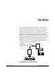
CTA 500dm The CTA 500 digital modem (CTA 500dm) is an optional device used with the Norstar Integrated Communication System (ICS). With ICS software, using release 2.0 or higher, the CTA 500dm provides integrated desktop solutions for digital networking applications. With optional Norstar Telephony API Service Provider (TAPI SP), the CTA 500dm also supports Computer Telephony Integration (CTI) services required for today's ofÞce environment.
CTA 500dm The CTA 500dm serves as a digital modem and terminal adapter (TA). A terminal adapter is a device that allows non-ISDN devices to work with ISDN. It provides reliable high speed end-to-end digital connectivity between your computer and a remote data server using the ICS and the public switched telephone network (PSTN) or Integrated Services Digital Network (ISDN).
CTA 500dm 3 Any PC equipped with Windows95, Internet application software, and a 16550 UART (115.2 kbit/s capability) can use the CTA 500dm. Applications The CTA 500dm can be used for any application that requires dial-up capability and uses Point-to-Point Protocol.
CTA 500dm CTA 500dm feature summary ¥ digital networking using PPP/MP ¥ simpliÞed installation and conÞguration using installation wizard ¥ high-speed network rate (56, 64, 112, or 128 kbit/s) ¥ high-speed serial port support (maximum 115,200 baud) ¥ integrated desktop solutions (Norstar set, data transfer, and CTI) ¥ bonding of two 56/64 kbit/s channels using MP ¥ dynamic bandwidth allocation between voice and data sessions ¥ data transfer using 3.
First-time setup This section guides you through the initial installation and setup of the CTA 500dm. Installation is carried out from the Personal Productivity Suite CD-ROM. Use the steps listed below to complete the installation. 1. Make the physical connections to the CTA 500dm. See Installation and setup 2. ConÞgure the ICS for the CTA 500dm. See Setting up the ICS 3. ConÞgure the Com port on the PC for the CTA 500dm. See ConÞguring the PC serial port 4.
First-time setup CTA 500dm On Line Guide P0873832 Issue 05
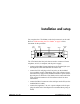
Installation and setup You can place the CTA 500dm on the desk or mount it on the wall. Refer to ÒWall mounting the CTA 500dmÓ on page 8 of this document for the procedure. Telephone KSU Port DB-25 9 V dc Power LED The CTA 500dm has four jacks that are used to connect a Norstar telephone, an ICS, a computer, and the power supply.
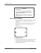
Installation and setup CAUTION! Shock hazard For protection from shock hazards, the CTA 500dm must receive power from an Approved Class 2 power pack equipped with a straight plug, center positive connector with a rating of 9 V dc at 0.6 A. Note: The approved power pack must be either CSA or C-UL certified in Canada, and either UL or NRTL listed in the United States. Wall mounting the CTA 500dm 1. Tape the paper template, supplied with the product, to the wall allowing 12.5 cm (6 in.
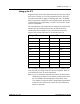
Installation and setup 9 Setting up the ICS Program the ICS for the CTA 500dm the same way that you program the ICS for a Norstar set. You can program line access, line pool codes and restrictions to apply to outgoing calls. The CTA 500dm must be assigned to a digital line or to a digital line pool. Refer to the ÒTerminals and sets programmingÓ section of your Installer Guide for more information. The CTA 500dm is a B2 channel device and must be assigned a B2 channel DN.
Installation and setup Setting up the PC Each PC operating system requires a different set up. Note: Installation using another vendorÕs protocol stack packages will differ. See the AT commands section of this document for information on conÞguring advanced operations on the CTA 500dm from your PC. See the Appendix for a list of the DB-25 pins used by the CTA 500dm.
Configuration Some operations that you can perform with the CTA 500dm include the following: ¥ ConÞguring the PC serial port ¥ Installing CTA 500dm and Norstar TAPI Service Provider software Note: Before you begin conÞguration, connect the ICS and the PC as described in the ÒInstallation and setupÓ section and power up the CTA 500dm.
Configuration Configuring the PC serial port ¥ Verify the port baud rate is set to 115,200 (default) using the Serial Interface Rate command. ¥ Set the character length, using the Set Data Bits command and parity, using the Set Parity command. The default is 8 bits with no parity (recommended). ¥ Set the ßow control using the Flow Control command. The default is hardware (recommended). Installing CTA 500dm and Norstar TAPI Service Provider software 1.
Configuration 13 7. Click Next. A message displays the name assigned to the installation. If you need more than one init string for the CTA 500dm, refer to ÒAdding multiple CTA 500dm conÞgurationsÓ on page 16 for the procedure. 8. Click OK. 9. Click Yes to automatically setup Internet access through your CTA 500dm. 10. Click Next when you see the message indicating that all network components required are present. 11. Click Yes to automatically setup a connection to your Internet service provider. 12.
Configuration 17. When the Connection Settings dialog box displays, enter the Internet service provider telephone number. 18. Click Next. 19. The installation is complete and you need to restart your computer before using the CTA 500dm. 20. Click the Finish button. Configuring the CTA 500dm (if not configured during installation) 1. From the Windows Start button, navigate to Programs, Norstar CTA 500dm, CTA 500dm ConÞguration. 2. The CTA 500dm ConÞguration Options dialog box is displayed. 3.
Configuration 15 Configure CTA 500dm to access PP/MP data calls 1. Double-click on the My Computer icon on your desktop. 2. Double-click Dial-Up Networking icon. 3. Double-click Make New Connection icon. 4. When the Make New Connection window displays, choose Norstar CTA 500dm modem from the pull-down menu. 5. Click the ConÞgure button. 6. Click the Connection tab. 7. Click the Advanced button. 8. In the Advanced Connection Settings window, type AT&D1 in the Extra settings box.
Configuration 9. Click OK. 10. Close all windows. Adding multiple CTA 500dm configurations 1. Click the Start button. 2. Choose Programs from the menu. 3. Choose CTA 500dm from the sub-menu. 4. Choose CTA 500dm conÞgurations. 5. Select the ConÞguration tab. 6. Choose settings for the required conÞguration. 7. Click OK. You now have another CTA 500dm conÞguration with different settings than the Þrst one. Make sure that you note the speciÞc settings when you create the connection icons.
Configuration 17 Upgrading the CTA 500dm software CTA 500dm software upgrades are periodically made available through your Norstar distributor. Contact your Norstar distributor for details about receiving software upgrades. Use the CTA 500dm conÞguration utility to display current settings or to update software. 1. Click the Browse button. 2. When Þle information displays, click Transmit. 3. Advanced connection settings can be deÞned using the setup wizard or the Enter Download State command.
Configuration CTA 500dm On Line Guide P0873832 Issue 05
Installing Norstar TAPI SP To use a CTA 500dm for TAPI applications, Norstar TSP must be installed. It can be installed at the same time as the CTA 500dm software via the Personal Productivity Suite (PPS) installation procedure, or it can be installed later from the PPS CD. Note: The current CTA 500dm conÞguration does not support dynamic bandwidth allocation if you donÕt have access to a line pool with more than two ISDN lines.
Installing Norstar TAPI SP 5. In the Dialing properties window, locate To access an outside line, first dial: and enter x for local (where x represent s the access code) and when applicable, y for long distance (where y represents the code to access a private network). 6. Click OK. 7. Close all windows. Installing Personal Call Manager The Personal Call Manager (PCM) application is supplied on the Norstar Personal Productivity Suite (PPS) CD-ROM. 1.
Installing Norstar TAPI SP 21 4. As the installation progresses, choose the appropriate options and click the Next button as required. 5. Once the Setup Complete window displays, click the Finish button. The program is installed and a PCM icon appears on the desktop. 6. To access the program, double-click the PCM icon. Using PCM for the first time When the PCM software is installed, you need to choose a TAPI line to enable PCM to use a TAPI-enabled device.
Installing Norstar TAPI SP Note: Refer to the Nortel ITAS web page for tips and information on other conÞgurations.
Resource sharing You can access information, software or peripheral devices (such as printers) that are installed on another PC from your PC when both PCs are equipped with a CTA 500dm and Win95 Plus! Dial-Up Server software. Note: Dial-Up Server software is available from either the Microsoft Plus! Pack or ISDN Accelerator Pack.
Resource sharing Installing Dial-Up Server If you use your PC to dial into other PCs, enable NetBEUI in the Server Types window. If other PCs will be dialling into your PC, enable IP, IPX and NetBEUI. 1. Install Dial-Up Server from either the Plus! Pack or the ISDN Accelerator Pack. 2. Open My Computer. 3. Open Dial-Up Networking. 4. From the Connections menu, select Dial-Up Server. 5. Select Allow caller access. 6. Select Change Password to apply a password to the connection.
Resource sharing 25 The Computer Name is required by PCs attempting to access your PC. 5. Close the Network window. The Control Panel window is still open. 6. Select one resource that you want to make available to other PCs, (for example, fax machine) and select it. 7. From the File menu select Properties. 8. Click the Sharing tab. 9. Select Shared As. 10. Enter a Share Name, any applicable Comment, and a Password. The Share Name and Password are required by PCs attempting to access your PC. 11.
Resource sharing 7. Select PPP: Windows95,... as Type of Dial-Up Server. 8. Check the to network box in Advanced options. 9. Check NetBEUI for Allowed Network Protocols. 10. Click OK. 11. Click OK. In the Dial-Up Networking window, double-click the icon of the modem you want to connect. The name and password are not yet required. Connecting to Resources on the Dial-Up Server Method one 1. Right-click on Network Neighborhood. 2. Select Find Computer. 3.
Resource sharing 27 resource on the Dial-Up Server under whichever Drive letter you select. 6. Enter the Resource you want to connect to in the Path Þeld. The syntax is: \\Computer Name\Share Name Note: Windows Explorer displays the new drive letter. 7. Click OK.
Resource sharing CTA 500dm On Line Guide P0873832 Issue 05
AT commands Use the following types of AT commands to communicate with your CTA 500dm. ¥ ProÞle commands ¥ State commands ¥ General commands ¥ S-registers commands ¥ Call Control commands ¥ TCM Ports Protocol Selection commands ¥ MP commands ¥ Serial Interface commands ¥ Serial Interface Control Lines commands ¥ Calling Line ID commands ¥ Caller ID Security commands To use an AT command, establish a HyperTerminal connection from the PC to the CTA 500dm.
AT commands Profile A proÞle deÞnes a CTA 500dm set-up. Each proÞle deÞnes the rate adaptation protocol and the options used with that protocol, the bearer capability and data rate of the next call dialed, the bearer capabilities and acceptable data rates for inbound calls, and the detailed operation of the serial interface port. The proÞle does not include stored dial strings. Three types of proÞles are available: ¥ The factory default which is Þxed.
AT commands 31 Load Stored Profile The Load Stored ProÞle Command Z[value] or &F[value] instructs the CTA 500dm to load all values that are stored in a proÞle. Value 0 indicates that the factory proÞle should be loaded. Value 1 indicates that the user proÞle should be loaded. Any calls in progress are disconnected when you use this command. The Z command selects the user proÞle (default value 1).The &F command selects the factory proÞle (default value 0).
AT commands Write Active Profile to Memory The Write Active ProÞle to Memory Command &W instructs the CTA 500dm to save the current conÞguration to permanent memory. The saved proÞle becomes the user proÞle. Result Codes OK Appears when the command is executed. ERROR Appears when the command could not be executed. State There are four states in which the CTA 500dm can interface with a computer. Command State No other device is connected, through the network interface, to the CTA 500dm.
AT commands 33 On-line Data State IA valid connection exists between the CTA 500dm and another device through the network interface. The selected rate adaptation protocol operates on data transferred through the interface between the CTA 500dm and the attached computer. You cannot enter the On-line Data State until the CTA 500dm establishes communication with the connected ICS.
AT commands Return to On-line Data State The Return to On-line Data State Command O instructs the CTA 500dm to return to the On-line Data State. Use this command to determine the number of B-channels active for rate adaptation protocols that use more than one B-channel, since the aggregate network rate is returned by the CONNECT indication. Result Codes CONNECT rate Appears when the connection is successfully resumed, where rate is the aggregate network rate (56000, 64000, 112000, or 128000).
AT commands 35 Result Codes OK Appears following successful completion of Þle transfer and Flash programming. ERROR Appears when the programming failed, and the original Flash contents remain unchanged. Escape Sequence The escape sequence pause, escape character, escape character, escape character, pause commands a transition from the On-line Data State to the On-line Command State. The pause before the assertion of the three escape characters is called the guard time.
AT commands Command Description Value En set echo command 0 turn echo off 1 turn echo on (default) &Zn= save dial string locations 0-9 (default 0) &Zn? display saved dial string locations 0-9 (default 0) Vn verbose control 0 numeric indications 1 full indications (default) Qn result code control 0 result codes are sent (default) 1 result codes are suppressed Xn call monitoring result code selection 0 connect only 1 connect rate only 2 connect rate only 3 connect rate and busy 4 conne
AT commands 37 Request Identification The Request IdentiÞcation Command I[value] instructs the CTA 500dm to return information about itself to the attached computer. The returned strings depend on the value passed in the command. See the possible values in the following table. If no value is speciÞed, the default value of 0 is used.
AT commands View Parameters The View Parameters Command &V[value] instructs the CTA 500dm to return stored values. The returned strings vary according to the value included in the command. (See the possible values in the following table.) If no value is speciÞed, the default value of 0 is used. Parameters are displayed in alphabetical order using a maximum width of 72 columns.
AT commands 39 Save Dial String The Save Dial String Command &Z[value=]dial string stores dial strings. The value indicates the location of the dial string (0-9). If no location is speciÞed, the default location (0) is used. The maximum length of the dial string is 20 characters. There can be a maximum of 10 stored dial strings. Saved dial strings are not part of proÞles. Result Codes OK Appears when the command was successfully completed. ERROR Appears when the command could not be completed.
AT commands Verbose Control The Verbose Control Command V[value] controls the indications sent by the CTA 500dm. A value of 0 instructs the CTA 500dm to send only numeric indications. A value of 1 instructs the CTA 500dm to send full indications. The default value is 1. The numeric responses and indications are shown in ÒNumeric CTA 500dm responsesÓ on page 83. Result Codes OK Appears when the value is supported. ERROR Appears when the selected value is unrecognized or is not supported.
AT commands 41 Call Monitoring Result Code Selection The Call Monitoring Result Code Selection Command X[value] controls the format of result codes sent by the CTA 500dm in verbose mode during call setup. (See possible values in the following table.) Values 1 and 2 are identical since the CTA 500dm does not support dial tone detection.
AT commands Set S-Register The Set S-Register Command Sregister number=[value] instructs the CTA 500dm to set the speciÞed S-register to a value. The register number must be speciÞed. An unspeciÞed value causes the register to have a default setting and an initial factory value. Result Codes OK Appears when the command is successfully completed. ERROR Appears when the chosen register or the value for the register is invalid.
AT commands 43 S-register set The following table shows the complete S-register set for the CTA 500dm. Not all options are supported for all versions of the CTA 500dm.
AT commands Call Control Call Control Commands are associated with making calls through the CTA 500dm. They are also understood by most computer software. Call Control commands summary Command Description Value Dx originate a call valid dial string or strings A answer a call H disconnect from current call Dial Command The Dial Command D[dial string][;] instructs the CTA 500dm to originate a call. The dial string consists of characters, up to the end of the line or to the optional; character.
AT commands 45 Character Use Svalue dial string is taken from a stored telephone number (value is the location of the stored number; see the “General” commands section for more information) The type of dialing depends on the type of network chosen to route the call, so the directives t (tone) and p (pulse) have no meaning and are ignored.
AT commands BUSY Appears when the connection was not completed due to detection of a busy indication in the network. ERROR Appears when the command was issued while in the Online Command State, if a stored dial string was speciÞed and the dial string was empty, or if the CTA 500dm is out-of-sync and the network is unavailable. Answer Command The Answer Command A instructs the CTA 500dm to answer an incoming call immediately.
AT commands 47 Hook Command The Hook Command H instructs the CTA 500dm to disconnect from the current call. Result Code OK Appears upon completion of the command. DCD is dropped immediately before the indication if &C is 1 (seeÒSerial Interface Control LinesÓ on page 56 for more details). Outgoing Call Control Calls processed by the CTA 500dm can use any of three ISDN bearer services. Additionally, the data rate over each of these bearer services can be set to either 56 kbit/s or 64 kbit/s.
AT commands The following table shows the values for bearer service selection. Value Bearer Service 0 data (default) 1 3.1 kHz audio 2 speech Result Codes OK Appears when the selected value is supported. ERROR Appears when the selected value is unrecognized or is not supported. Channel Speed Control The Channel Speed Control Command %A4=value instructs the CTA 500dm to use the speciÞed data rate for outgoing calls dialed over the B-channels of the TCM port of the CTA 500dm.
AT commands 49 messages. See ÒBearer CapabilitiesÓ on page 81 for more information. Note: At least one of the bearer rates must be enabled so that the CTA 500dm can accept incoming calls. Incoming Call Control commands summary Command Description Value %A93=n set speech bearer call answer 0 disabled (default) set 3.
AT commands Speech Bearer Call Answer Control The Speech Bearer Call Answer Control Command %A93=value allows the CTA 500dm to accept or reject incoming calls received over the speech bearer service. The following table shows the values for speech bearer service calls control. Value Speech Bearer Service Calls 0 rejected (default) 1 accepted Result Codes OK Sent if the selected value is understood. ERROR Sent if the selected value is not recognized or is not supported.
AT commands 51 Data Bearer Call Answer Control The Data Bearer Call Answer Control Command %A95=value allows the CTA 500dm to accept or reject incoming calls received over the data bearer service. The following table shows the values for data bearer service calls control. Value Data Bearer Service Calls 0 rejected (default) 1 accepted Result Codes OK Appears when the selected value is understood. ERROR Appears when the selected value is not recognized or is not supported.
AT commands TCM Ports Protocol Selection The TCM Port Protocol Selection Command controls use of the TCM port of the CTA 500dm. Stored values are part of the CTA 500dm proÞles.
AT commands 53 MP The following command is available for CTA 500dm versions that support MP. MP command summary Command Description Value @B0=n set number of links in MP bundle 1 single channel used 2 both channels used (default) Rate Multiplier The Rate Multiplier Command @B0=value controls the number of links used when the CTA 500dm is operating in the MP mode. A value of 1 indicates that a single link may be used. A value of 2 indicates that two links may be used. The default value is 2.
AT commands Serial Interface This section describes the commands associated with the serial interface. All values are saved as part of the CTA 500dm proÞle.
AT commands 55 Result Codes OK Appears when the value is supported. ERROR Appears when the selected value is not recognized or is not supported. Set Parity The Set Parity Command &P3=value sets the parity value of the interface between the CTA 500dm and the attached computer. The following table shows the supported values. Value Use 0 none (default) 1 odd 2 even Result Codes OK Appears when the value is supported. ERROR Appears when the selected value is not recognized or is not supported.
AT commands Set Stop Bits The Set Stop Bits Command &P6=value sets the number of stop bits on the interface between the CTA 500dm and the attached computer. The following table shows the supported values. Value Use 0 one stop bit (default) 1 one and one-half stop bits 2 two stop bits Result Codes OK Appears when the value is supported. ERROR Appears when the selected value is not recognized or is not supported.
AT commands 57 Serial Interface Control Lines commands summary Command Description Value \Qn serial interface flow control 0 none 1 bidirectional XON/XOFF 2 not supported 3 bidirectional RTS/CTS (default) 4 not supported &Cn DCD operation 0 always on 1 tracks connection (default) 2 always on, except temporarily after disconnect &Dn DTR operation 0 ignored (default) 1 enter command state 2 hang-up and disable auto while DTR is down 3 hang-up and reset port &Rn CTS operation 0 CTS follows RTS
AT commands Value Use 4 not supported Note: XON/XOFF ßow control uses characters often referred to as control-Q and control-S. Result Codes OK Appears when the value is supported. ERROR Appears when the selected value is not recognized or is not supported.
AT commands 59 DCD Operation &Cvalue The DCD Operation Command sets the operation of the DCD pin. The following table shows the allowable values. Value Use 0 always on 1 tracks connection (default) 2 always on except temporarily after a disconnect The DCD pin tracks the connection and asserts when the CTA 500dm has successfully completed a physical layer connection over one of the network B-channels. It does not indicate the successful negotiation of a rate adaptation protocol.
AT commands Value Use 2 close all connections, change to the Command State (Auto answer is disabled while the DTR is down) 3 as above, followed by a reset of the CTA 500dm All modes of operation may not apply with all selections of rate adaptation protocols. When &D is set to 3, assertion of the DTR signal causes a software reset of the CTA 500dm, even if it is already in the command state.
AT commands 61 DSR Operation The DSR Operation Command &Svalue sets the operation of the DSR pin. The following table shows the allowable values. Value Use 0 DSR is always on (default) 1 DSR is on after protocol is installed (not supported) The DSR signal is turned on at start-up to be compatible with Windows95 Plug and Play requirements. This corresponds to a &S setting of 0. No other DSR values are supported. Result Codes OK Appears when the value is supported.
AT commands indication is modiÞed to be RING:1234567. This is called the concatenated format. The second format is a Tag = Value pair, where the only supported tag is NMBR. The same example would return the string NMBR = 1234567 on its own line after the Þrst RING indication. A query may be sent during ringing that returns the calling line ID information. This feature is independent of the delivery enable feature.
AT commands 63 returns an ASCII string containing the calling line ID information. This command is valid only during incoming calls and is independent of the Calling Line ID Delivery Control. If the calling line ID is unknown, the returned string is UNKNOWN. There is no numeric form to the UNKNOWN string. If the calling line ID is known, it is returned as a single text string, as in the concatenated format of the Calling Line ID Delivery Control.
AT commands Caller ID security commands summary Command Description Value @Sn select CLID security mode 0 disabled (default) 1 enable CLID screening mode 2 enable CLID blocking mode @A=n add specified number to CLID security list @D=n remove specified number from CLID security list @C clear all stored numbers &V4 display stored numbers Caller ID Security Mode Selection The Caller ID Security Mode Selection Command @Svalue allows enabling of either CLID screening or blocking, or to disabli
AT commands 65 allows addition of a number to the Caller ID security list. You can store up to ten 13-digit numbers in the list. Result Codes OK Appears when the number is successfully added to the list. ERROR Appears when the list contains ten numbers or the number is longer than 13 digits. Delete Number The Delete Number Command @D=number allows removal of a number from the Caller ID security list. Result Codes OK Appears when the number is successfully removed from the list.
AT commands Summary of AT commands Command Description Value &Fn load active profile from factory profile 0 factory profile (default) load active profile from stored profile 0 factory profile select profile to load into active profile on power-up 0 factory profile (default) Zn &Yn 1 user profile 1 user profile (default) 1 user profile &W save active profile to memory O return to On-line Data State Yxxxx enter Download State XXXX=Nor* In request identification 0 product ID (default)
AT commands 67 Command Description Value Xn call monitoring result code selection 0 connect only 1 connect rate only 2 connect rate only 3 connect rate and busy 4 connect rate and busy (default) Sn= set value to S-register depends on register Sn? query S-register value S0 number of rings until answer 0-255 (default 1) S1 ring count (read only) 0-255 (default 0) S2 escape character 0-127 (default 43) 128-255 (disables escape sequence) S3 carriage return character 0-127 (default 13) S4
AT commands Command Description Value %A98=n set outgoing call type 0 data bearer service (default) 1 3.1 kHz audio bearer service 2 speech bearer service %A4=n %A93=n %A94=n %A95=n %A5=n %A2=n select speed of TCM channels, outgoing calls 0 64 kbit/s set speech bearer call answer 0 disabled (default) set 3.
AT commands 69 Command Description Value &P6=n serial interface stop bits per character 0 one stop bit (default) 1 one and one-half stop bits 2 two stop bits \Qn serial interface flow control 0 none 1 bidirectional XON/XOFF 2 not supported 3 bidirectional RTS/CTS (default) 4 not supported &Cn DCD operation 0 always on 1 tracks connection (default) 2 always on, except temporarily after disconnect &Dn DTR operation 0 ignored (default) 1 enter command state 2 hang-up and disable auto while DTR i
AT commands Command Description @A=n add specified number to CLID security list @D=n remove specified number from CLID security list @C clear all stored numbers &V4 display stored numbers CTA 500dm On Line Guide Value P0873832 Issue 05
Troubleshooting Power problem? There is no power to the CTA 500dm. ¥ Make sure that the power adapter is securely plugged into the CTA 500dm. ¥ Make sure that the power adapter is plugged into a live outlet. There is power but the CTA 500dm cannot establish a link. ¥ Make sure that the TCM cable is connected. ¥ Check that the LED is on. See ÒCTA 500dm LEDÓ on page 82 for more information. ¥ Perform a device restart. LED problem? The LED is flashing quickly on power-up.
Troubleshooting ¥ If the cable is faulty or the ICS is down, the attached phone will also not work. AT command problem? The CTA 500dm does not respond to AT commands sent from your PC. ¥ Make sure that your PC, terminal or other DTE is conÞgured correctly. ¥ Check the DTE connection. If the DTE is conÞgured as a DCE you may need a null modem cable. ¥ Check that your PC or DTE is conÞgured to expect CD and CTS signals. See ÒSerial Interface Control LinesÓ on page 56 for more information.
Troubleshooting 73 AT commands do not appear. ¥ To see the commands that you type in a HyperTerminal window, you must Disconnect, then Connect again. Using HyperTerminal, the message “Unable to open COMx port” appears. ¥ The CTA 500dm may be in use by another application (for instance, Dial-Up Networking). Data call problem? Data calls are not answered automatically. ¥ Make sure that rings until answer S0 is not set to 0. See ÒSregistersÓ on page 41 for more information.
Troubleshooting properties. Ensure ÒUse country and area codeÓ is deselected if using MP with two dial out numbers. The PC receives bad data after a data call connection. ¥ Make sure that the CTA 500dm and the remote device are set to the same rate adaptation protocol. See ÒRate adaptation protocol speciÞcationsÓ on page 80 for more information. ¥ The remote device may be conÞgured for synchronous transmission. The CTA 500dm does not support synchronous operation.
Appendix Canadian & US Safety Installation Instructions Please Read Carefully WARNING: To avoid electrical shock hazard to personnel or equipment damage observe the following precautions when installing telephone equipment: 1. Never install telephone wiring during a lightning storm. 2. Never install telephone jacks in wet locations unless the jack is specifically designed for wet locations. 3.
Appendix For equipment with external mains adapters: CAUTION: Intended for use in a protected environment. Use only a Nortel supplied or recommended mains power adapter marked as indicated below: Mains Supply Output (Input Voltage) Voltage Rated Current Approval Markings Polarity Marking 240 V ac 9 V dc 0.6 A maximum CLASS II POWER SUPPLY - VE +VE 230 V ac 9 V dc 0.6 A maximum CLASS II POWER SUPPLY - VE +VE 110 V ac 9 V dc 0.
Appendix 77 7. Do not allow anything to rest on the power cord. Do not locate this product where the cord will be abused by persons walking on it. 8. Do not overload wall outlets and extension cords as this can result in the risk of fire or electric shock. 9. Never spill liquid of any kind on the product. 10. To reduce the risk of electric shock, do not disassemble this product, but have it sent to a qualified service person when service or repair work is required. 11.
Appendix (PSTN). The FCC registration number appears on a sticker afÞxed to the equipment. For more regulatory information, refer to Norstar Installation Guide that came with your system. EMI/EMC Note: This device complies with Class A EMI requirements when connected to host equipment that meets Class A and Class B when connected to host equipment that meets Class B. For more information about compliance, refer to Norstar Installation Guide that came with your system.
Appendix 79 These limits are designed to provide reasonable protection against harmful interference in a residential installation. This equipment generates, uses and can radiate radio frequency energy and, if not installed and used in accordance with the instructions, may cause harmful interference to radio communications. However, there is no guarantee that interference will not occur in a particular installation.
Appendix Rate adaptation protocol specifications The CTA 500dm supports two rate adaptation protocols. These protocols allow data leaving the computer to be properly carried over the network to another computer or LAN. The CTA 500dm supports the following protocols: ¥ Point-to-Point Protocol ¥ Multilink PPP Point-to-Point Protocol PPP is used when only a single channel is desired.
Appendix 81 other authentication protocol is selected, the CTA 500dm will not be able to use MP and the call must be redialed using PPP. Link Assumptions For PPP and MP, it is assumed that the links are CRC-16 with Maximum Receive Units (MRU) less than 1750 bytes. For MP, it is assumed that call back is not required and that both links can be identically conÞgured. Bearer Capabilities The use of ISDN and digital networks allows a user to select a number of different bearer capabilities and data rates.
Appendix CTA 500dm LED The status LED is on the back of the CTA 500dm. It provides information about the current state of the CTA 500dm and the B-channels based on its ßashing pattern. The following table shows the LED ßashing patterns and CTA 500dm states.
Appendix 83 Numeric CTA 500dm responses Numeric response Indication 0 OK 1 RING 2:number RING:number 3 NO CARRIER 4 ERROR 6 NO DIALTONE (not used) 7 BUSY 56 CONNECT 56000 64 CONNECT 64000 112 CONNECT 112000 120 CONNECT 120000 (if supported) 128 CONNECT 128000 1000 SEND PROGRAM FILE USING YMODEM-G Initialization strings The following table shows some suggested initialization strings. In all examples, Flow Control is set to hardware (\q3) and DTR Operation is set to hang up (&d2).
Appendix DB-25 and DB-9 signal summary The following tables show which DB-25 and DB-9 pins are used by the CTA 500dm and what the signals are used for by the CTA 500dm.
Appendix 85 DB-9 connection DB-9 pin RS-232 function CTA 500dm function 1 Received Line Signal Detector DCD 2 Received Data RD 3 Transmitted Data TD 4 DTE Ready DTR 5 Signal Common GND 6 DCE Ready DSR 7 Request to Send/Ready for Receiving RTS 8 Clear to Send CTS 9 Ring Indicator RI Acronyms used in this document ATMÑAsynchronous transfer mode CHAPÑChallenge Handshake Authentication Protocol CSAÑCanadian Standards Association CTA 500dmÑComputer Telephony Adapter digital modem m
Appendix LEDÑLight Emitting Diode MPÑPoint-to-Point Protocol/Multi-link Protocol MRUÑMaximum Receive Units PAPÑPassword Authentication Protocol PPPÑPoint-to-Point Protocol PSDNÑPublic Switched Digital Network PSTNÑPublic Switched Telephone Network TAÑTerminal Adapter TAPI SPÑTelephony Application Programming Interface Service Provider TCP/IPÑTransmission Control Protocol and Internet Protocol UARTÑUniversal asynchronous receiver/transmitter CTA 500dm On Line Guide P0873832 Issue 05