HOTWIRE 8600 DIGITAL SUBSCRIBER LINE ACCESS MULTIPLEXER (DSLAM) INSTALLATION GUIDE Document No.
Copyright 1997 Paradyne Corporation. All rights reserved. Printed in U.S.A. Notice This publication is protected by federal copyright law. No part of this publication may be copied or distributed, transmitted, transcribed, stored in a retrieval system, or translated into any human or computer language in any form or by any means, electronic, mechanical, magnetic, manual or otherwise, or disclosed to third parties without the express written permission of Paradyne Corporation, 8545 126th Avenue North, P.
Important Regulatory Information Important Safety Instructions 1. Read and follow all warning notices and instructions marked on the product or included in the manual. 2. The AC product version is intended to be used with a 3-wire grounding type plug – a plug which has a grounding pin. This is a safety feature. Equipment grounding is vital to ensure safe operation. Do not defeat the purpose of the grounding type plug by modifying the plug or using an adapter.
Important Regulatory Information EMI Warnings ! WARNING: This equipment has been tested and found to comply with the limits for a Class A digital device, pursuant to Part 15 of the FCC rules. These limits are designed to provide reasonable protection against harmful interference when the equipment is operated in a commercial environment.
Important Regulatory Information CE Marking When the product is marked with the CE mark, this demonstrates full compliance with the following European Directives: — Directive 72/73/EEC – Council Directive of 19 February 1973 on the harmonization of the laws of the member states relating to electrical equipment designed for use within certain voltage limits, as amended by Directive 93/68EEC.
Contents About This Guide Document Purpose and Intended Audience . . . . . . . . . . . . . . . . . . . . . . . . . iii Document Summary . . . . . . . . . . . . . . . . . . . . . . . . . . . . . . . . . . . . . . . . . . . . . iv Product-Related Documents . . . . . . . . . . . . . . . . . . . . . . . . . . . . . . . . . . . . . . v 1 About the HotWire 8600 DSLAM What is the HotWire 8600 DSLAM? . . . . . . . . . . . . . . . . . . . . . . . . . . . . . . . 1-1 HotWire 8600 DSLAM Components . . . .
Contents Making Cable Connections . . . . . . . . . . . . . . . . . . . . . . . . . . . . . . . . . . . . . . . 2-22 Special Connection Considerations . . . . . . . . . . . . . . . . . . . . . . . . . . . . 2-22 Connecting to a POTS Splitter or an MDF . . . . . . . . . . . . . . . . . . . . . . 2-23 Connecting the DSL Cards to the Ethernet Hubs or Switches . . . . . . 2-24 Connecting to an SNMP Management System . . . . . . . . . . . . . . . . . . 2-25 Connecting to a Terminal or Laptop Computer . . . .
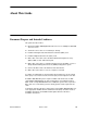
About This Guide Document Purpose and Intended Audience This guide describes how to: Mount the HotWire 8600 Digital Subscriber Line Access Multiplexer (DSLAM) chassis in a rack Stack two to three chassis on a tabletop or desktop Install the Management Communications Controller (MCC) card Install the Digital Subscriber Line (DSL) cards Make cable connections to the CO POTS (Plain Old Telephone Service) Splitter, MDF, or other demarcation point Make cable connection to a network manage
About This Guide Document Summary iv Section Description Chapter 1 About the HotWire 8600 DSLAM. Provides an overview of the HotWire 8600 DSLAM chassis, its components, and its features. Chapter 2 Installing and Connecting the Hardware. Describes how to mount the chassis, stack two or more chassis, install the MCC and DSL cards, and make cable connections to the network. Chapter 3 Initial Setup Instructions. Describes how to configure the MCC card for remote configuration.
About This Guide Product-Related Documents Document Number Document Title 5020-A2-GN10 HotWire POTS Splitter Central Office Installation Instructions 5030-A2-GN10 HotWire 5030 POTS Splitter Customer Premises Installation Instructions 5034-A2-GN10 HotWire 5034 Indoor POTS Splitter Installation Instructions 5216-A2-GN10 HotWire 5216 Remote Termination Unit (RTU) Installation Instructions 5246-A2-GN10 HotWire 5246 Remote Termination Unit (RTU) Installation Instructions 5446-A2-GN10 HotWire 5446 R
About the HotWire 8600 DSLAM 1 What is the HotWire 8600 DSLAM? The HotWire 8600 Digital Subscriber Line Access Multiplexer (DSLAM), which can be installed in the Central Office (CO) or at a customer location adjacent to the CO, is a low start-up cost alternative to the HotWire 8800 DSLAM chassis. Through the use of Digital Subscriber Line technology, DSLAM provides simultaneous high-speed data access (digital) and POTS service (analog) over the same twisted-pair telephone line.
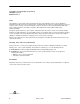
About the HotWire 8600 DSLAM The following illustration shows a high-level view of a HotWire configuration: NOTE: You may make cable connections from a DSL card directly to a Main Distribution Frame (MDF) or through a POTS splitter to an MDF, but not both.
About the HotWire 8600 DSLAM B A B A B 4 5 6 1 .. . . A RADSL 8546 RADSL 8546 3 2 1 LINE LAN/WAN SLOT MANAGEMENT 8000 4 3 2 C ol D DC PWR ALM MCC 4 3 2 PO SL D RT SL 1 PO ol C X R R X TX FAN STACK POSITION 1 RT ET N X ol C R ER H ET ET N TX H ET 3 2 48VDC CLASS 2 OR LIMITED PWR SOURCE ER EM O K Alr m Te st ST SY DC FUSES T4A, MIN.
About the HotWire 8600 DSLAM HotWire 8600 DSLAM Features The HotWire 8600 DSLAM system has the following features: Power Redundancy Two versions of the HotWire 8600 DSLAM chassis are available: — ac power — dc power The ac version can also be connected to a dc source to provide power redundancy. When using the dc version, two separate dc sources may be employed to provide power redundancy. If one power source fails, the other source provides all of the power needed by the system.
8600-A2-GN20-20 October 1997 RADSL 8546 4 3 2 1 C ol R X TX PO RT 8546 D SL RADSL 4 3 2 1 C ol PO RT 8546 D SL RADSL 4 3 2 1 C ol PO RT 8546 D SL RADSL 4 3 2 1 RT ol C PO 8546 SL D RADSL 4 3 2 1 RT ol C PO 8546 SL D RADSL 4 3 2 1 RT ol C PO 8546 SL D RADSL 4 3 2 1 RT ol C PO 8546 SL D RADSL 4 3 2 1 RT ol C PO Te st O K Alrm SY ST EM ET H ER N ET 8546 SL D R X TX Te st O K Alrm SY ST EM ET H ER N ET RADSL 4
About the HotWire 8600 DSLAM In addition, the HotWire 8600 DSLAM chassis can be placed on a desk or table, and stacked on top of each other. For stability, do not set more than three HotWire 8600 chassis on top of each other in a single stack on a desk or table top. Two physical stacks of three chassis can be interconnected to provide shared management access for six HotWire 8600 chassis.
Installing and Connecting the Hardware 2 Overview The HotWire 8600 DSLAM chassis can be mounted in a 19- or 23-inch wide rack. These 8600 chassis can also be placed on a desk or table or stacked on top of each other. Up to three chassis can be physically stacked on top of each other.
Installing and Connecting the Hardware Package Contents The HotWire 8600 DSLAM chassis, as shipped, consists of the following: B A B A B 4 5 6 1 .. A RADSL 8546 RADSL 8546 3 2 1 LINE LAN/WAN SLOT MANAGEMENT 8000 4 3 D DC PWR ALM C ol R X TX FAN MCC 4 3 2 PO SL D RT 2 SL 1 PO ol C X N . . 1 RT ET ol C N X R TX ER H ET ET R ER H ET 3 2 48VDC CLASS 2 OR LIMITED PWR SOURCE TX O K Alr m Te st ST SY DC FUSES T4A, MIN.
Installing and Connecting the Hardware and check for physical damage. If the 8600 chassis shows signs of shipping damage, report this immediately to your shipping and sales representatives. Pre-installation Considerations Consider the following before performing installation of the 8600 chassis: Installation Site Your installation site should be well-ventilated, clean, and free of environmental extremes.
Installing and Connecting the Hardware 9-pin serial port. For connection to a modem, you will need a NULL modem adapter. CAUTION: Use of any non-twisted pair wiring arrangements, such as jumpers, can cause reduction in overall DSL reach performance, even over short distances. Please refer to the Special Notice shipped with this product. Pin assignments are described in Appendix B, Pinouts.
Installing and Connecting the Hardware HotWire 8600 DSLAM Chassis Installation You will need a large, flat-blade screwdriver and a Phillips screwdriver to install the 8600 chassis in a commercial EIA-standard 19- or 23-inch rack on a desk or table. The HotWire 8600 DSLAM chassis is designed to be stacked one on top of the other on a desktop or table, or mounted in a 19-or 23-inch rack. Up to three 8600 chassis can be stacked on a table or desktop.
Installing and Connecting the Hardware 4. Change the setting of the rotary STACK POSITION switch to the appropriate position of the chassis. Set the switch so that the white line points to the position number. — The base chassis containing the MCC card must be set to Stack Position 1; — The chassis directly on top of the base chassis must be set to Stack Position 2; — The chassis directly on top of chassis #2 must be set to Stack Position 3, and so on.
Installing and Connecting the Hardware National Equipment Building Standards (NEBS) The following must be taken into consideration for compliance with NEBS requirements. Connection to the CO Ground Lug Procedure 1. Strip back the insulation approximately 1/4- to 3/8-inch on 14 AWG copper wire. 2. Loosen the screw on the GND lug located on the rear surface at the center of the HotWire 8600 DSLAM cover. 3. Insert the stripped end of the wire into the open end of the GND lug and tighten the lug’s screw.
Installing and Connecting the Hardware Interconnecting 8600 Systems Procedure To interconnect multiple 8600 systems: 1. Connect the end of an 8-pin modular cable into the Management OUT port of the base chassis. 2. Dress the 8-pin modular cable to the left and under the chassis, behind the foot, and up the side of the unit. 3. Plug the other end of the 8-pin modular cable into the Management IN port of the 8600 chassis above, dressing the cable as in the previous step. 4.
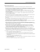
Installing and Connecting the Hardware The software identifies each circuit card in the stack by a Slot Number. The following illustration shows the designated number for each DSL card slot in a stack.
Installing and Connecting the Hardware Installing the 8600 Chassis in a Rack with Threaded Screw Holes Procedure To install the 8600 chassis in a rack that has threaded screw holes: 1. Install the mounting brackets on the 8600 chassis by removing the two front screws on each side of the unit. You will reuse these screws to secure the mounting brackets to the 8600 chassis. — For a 19-inch rack installation, the notched flange of the mounting bracket is placed against the side of the 8600 chassis.
Installing and Connecting the Hardware 2. Secure the mounting brackets to the 8600 chassis by using the screws removed from the sides of the unit. 3. Determine the preferred placement of the 8600 chassis in the rack. Then, mark the appropriate locations for the mounting screws on the rack. 4. Place the 8600 chassis against the front rails of the rack and secure with the appropriate mounting screws. Repeat these steps for each succeeding 8600 chassis.
Installing and Connecting the Hardware Installing the 8600 Chassis in a Rack without Threaded Screw Holes Procedure To install the 8600 chassis in a rack that does not have threaded screw holes: 1. Install the mounting brackets on the 8600 chassis. — For a 19-inch rack installation, the notched flange of the mounting bracket is placed against the side of the 8600 chassis. — For a 23-inch rack installation, the smaller flange of the mounting bracket is placed against the side of the 8600 chassis. 2.
Installing and Connecting the Hardware Supplying Power The HotWire 8600 DSLAM chassis is available in two versions: H dc power (– 40.0 to – 60.0 Vdc; maximum current draw is 2 amps) — The dc version has two separate dc inputs, A and B, to provide power redundancy. H ac power (100 – 250V; 50 – 60 Hz; maximum current draw is 3 amps @ 110 Vac) — The ac version can provide power redundancy if a separate – 48 Vdc source is connected to the B input terminal.
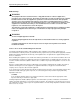
Installing and Connecting the Hardware 2. Dress the wires under the 8600 chassis to the left behind the support foot. AC T5A 250V –48V A RTN B A B AC INPUT 48VDC CLASS 2 OR LIMITED PWR SOUR NF G RT B -48V A B A T PU C IN VD 48 97-15446-01 3. Power the HotWire 8600 DSLAM chassis. 4. Make sure the DC PWR A LED on the front panel is ON (green).
Installing and Connecting the Hardware Insert Power Source. . . Into the . . . A’s wire – 48V A input terminal. B’s wire – 48V B input terminal. A’s RTN wire RTN A (return) terminal. B’s RTN wire RTN B (return) terminal. 2. Dress the wires under the 8600 chassis to the left behind the support foot. AC T5A 250V –48V A RTN B A B AC INPUT 48VDC CLASS 2 OR LIMITED PWR SOURCE NF G RT B -48V A B A VD 48 97-15371-01 3.
Installing and Connecting the Hardware Using Only AC Power Source Procedure To supply power to the 8600 chassis using a single ac power source: 1. Plug the ac power cord into the AC INPUT connector on the Interface Panel. N RT V B -48 A B A T PU DC IN V 48 NF G RT B -48V A B A T PU C IN VD 48 97-15365 2. Plug the other end of the ac power cord into your ac power receptacle. NOTE: The ac power source should be a non-switched outlet to prevent accidentally turning off power. 3.
Installing and Connecting the Hardware 1. Plug the ac power cord into the AC INPUT connector on the Interface Panel. 2. Insert the following wires in the appropriate terminal and securely fasten each wire by tightening the screw above it. The insulation should be fully within the terminal block and no bare wire should be exposed outside of the block. NOTE: You should clearly label these power source wires as – 48V and RTN respectively. Insert Power Source B’s . . . Into the . . .
Installing and Connecting the Hardware Installing the MCC Card Use a small- to medium-size flat-blade screwdriver to install the MCC card. NOTE: All standalone 8600 chassis (i.e., chassis that are not daisy-chained to other HotWire 8600 DSLAM chassis) require an MCC card, but only the base chassis of a multi-system stack requires an MCC card. Do not discard filler plates.
Installing and Connecting the Hardware 3. Carefully slide the MCC card into the slot. Gently, but firmly, push the card until it engages its mating connectors on the backplane. 4. Press on the right side of the MCC’s front panel with one hand and on the back of the 8600 chassis with the other until the MCC’s connector seats in its mating connector. 5. Make sure the OK SYSTEM indicator on the MCC faceplate is ON (green). if not, refer to Chapter 4, Troubleshooting. 6.
Installing and Connecting the Hardware Procedure To install a DSL card: 1. Remove the filler plate from the desired slot. 2. Hold the DSL card horizontally with the components on top and insert it into the left and right card guides. 3 AC T5A 250V 48VDC CLASS 2 OR LIMITED PWR SOURCE A ALM ol X A RADSL 4 RT 3 2 1 PO SL 1 8000 R TX C ol X LINE LAN/WAN SLOT MANAGEMENT C R DC PWR TX FAN ER N . . D ..
Installing and Connecting the Hardware Verifying the Installation To verify the hardware installation, observe the following indicators: The PWR A and/or PWR B LEDs on the front panel must be in the ON state (green): — If you are using a single – 48 Vdc power source, then only the green DC PWR A LED will be ON. — If you are using dual Vdc power sources, then both the green DC PWR A and DC PWR B LEDs will be ON. — If you are using a single ac power source, then the green PWR A LED must be ON.
Installing and Connecting the Hardware Making Cable Connections This section provides the instructions you need to make the necessary cable connections to: POTS splitter shelf or MDF Ethernet hubs or switches SNMP management system Terminal, laptop computer, or modem Special Connection Considerations There are several steps that you must take to maximize loop reach.
Installing and Connecting the Hardware Connecting to a POTS Splitter or an MDF You can connect the HotWire 8600 DSLAM chassis to a POTS splitter shelf or to a Main Distributing Frame (MDF). NOTE: If you are connecting the HotWire 8600 DSLAM to a CO POTS splitter, this procedure assumes that the CO POTS splitter shelf is already installed. For information on how to install the CO POTS splitter, refer to the HotWire POTS Splitter Central Office Installation Instructions.
Installing and Connecting the Hardware Connecting the DSL Cards to the Ethernet Hubs or Switches Procedure To connect the DSL cards to the Ethernet hubs or switches: 1. Plug the end of an 8-pin modular cable into the appropriate LAN/WAN SLOT port of the 8600 chassis. For example, if you want to connect to a DSL card in Slot 2, insert the 8-pin modular cable into the LAN/WAN Slot #2. 2. Run the 8-pin modular cable under the 8600 chassis and behind the left leg. 3.
Installing and Connecting the Hardware Connecting to an SNMP Management System Procedure To connect the HotWire 8600 DSLAM base chassis (i.e., the chassis that contains the MCC card) to an SNMP management system: 1. Plug the end of an 8-pin modular cable into the MANAGEMENT MCC port of the HotWire 8600 DSLAM base chassis. 2. Dress the 8-pin cable under the 8600 chassis to the left and behind the left support foot. 3.
Installing and Connecting the Hardware Connecting to a Terminal or Laptop Computer Procedure To connect the HotWire 8600 DSLAM chassis to a terminal or laptop computer: 1. Connect an 8-pin modular plug-ended serial cable into the MANAGEMENT SERIAL port of the HotWire 8600. 2. Dress the serial cable under the 8600 chassis, to the left and behind the left support foot. 3.
Installing and Connecting the Hardware Connecting to a Modem for Remote Management Before connecting the HotWire 8600 DSLAM to a dial up modem, configure the modem with the following settings: H Set the modem for auto answer. For example, ATS0=1. H Turn off character echo. For example, ATE0. H Enable result codes in originate mode only. For example, ATQ2. H Set the modem to ignore Data Terminal Ready (DTR). For example, AT&D0.
Installing and Connecting the Hardware Connecting to a HotWire 8600 DSLAM Via Telnet You can connect to a HotWire 8600 DSLAM via a telnet session from either a workstation or PC that has access to the Management Domain LAN. Procedure If you are using a Solaris 2 or SUN OS 4 workstation: 1. Execute a window manager program, such as OpenWin. 2. Execute a terminal emulator program. 3. Set terminal type to VT100. 4.
Initial Setup Instructions 3 Setting the IP Address and Subnet Mask on the MCC for Remote Configuration You can fully configure the MCC and DSL cards at the Central Office (CO) using the console terminal. However, if you want to perform remote card configuration from a network management workstation via a telnet session, you must set the IP address and subnet mask of the MCC card using a terminal connected to the DSLAM’s serial console interface before you can configure the cards remotely.
Initial Setup Instructions Procedure To set the IP address and subnet mask from the console terminal: 1. Power up the chassis. After the self-test completes, the Who Am I screen will appear. 2. From the Who Am I screen, enter the Management Domain IP address of the MCC card and press the Return key. For example, if the IP address of the MCC card is 198.152.152.50, type this value at the (nnn.nnn.nnn.nnn): prompt as illustrated below.
Initial Setup Instructions 3. Do one of the following at the (nnn.nnn.nnn.nnn): prompt: — To accept the subnet mask, press Return. — To enter a different subnet mask, enter a new subnet mask and press Return. The system highlights the OK to restart?: prompt. 4. Type y at the yes/no: prompt to restart the card or n to decline the restart. If you type y, the card restarts. You can now log in remotely using telnet or an SNMP NMS to configure the cards.
Troubleshooting 4 Power Failure Troubleshooting Procedures The following illustrates the steps to take when either the PWR A or PWR B LEDs, or both, are OFF. 1. Using a voltmeter, check for power at the terminal connections. — If there is power, call your sales representative for service to the 8600. 2. If there is no power at the terminal, call the appropriate electrician. Power LED is OFF 8600-A2-GN20-20 PROBLEM: One of the DC PWR LEDs is OFF due to a failure in a single chassis within a stack.
Troubleshooting Fan Alarm LED is ON PROBLEM: One of the chassis in the stack is reporting a fan failure (i.e., the FAN ALM LED of that chassis is on). A built-in feature shuts off power to the circuit cards if a chassis overheats because of fan failure. If the temperature in the chassis reaches 70°C, power to the cards in the chassis is turned off automatically. Power is turned on when the temperature drops below 60°C. ACTION: Go to the stack to see which chassis is reporting the fan alarm.
LEDs A Overview This appendix describes the meaning of the LEDs on the HotWire 8600 DSLAM chassis and MCC card. HotWire 8600 DSLAM Chassis The 8600 chassis allows addressable diagnostic connectivity between the MCC and each of the DSL cards. It also converts and distributes – 48V power to the cards in the chassis. In addition, it provides fans to cool the circuit cards. The following table describes the meaning and states of the LEDs on the front panel of the carrier. LED LED is . . . Indicating . . .
LEDs MCC Card ST SY The MCC card provides diagnostic connectivity to the HotWire 8600/8800 DSL cards. It provides the circuitry for both Ethernet and serial interfaces to the HotWire 8600 DSLAM chassis. The MCC card provides mid-level management functions for SNMP management of the DSL cards. EM O t K lrm es A T The following table describes the meaning and states of the LEDs on the MCC card faceplate. ET LED LED is . . . Indicating . . .
Pinouts B 8-Pin Modular Ethernet Connector for MCC Management Connector Pinouts The 8-pin interface for the MCC Management 10BaseT Ethernet connection has the following pin assignments: Pin Number Use 1 TX Data + 2 TX Data – 3 RX Data + 4 Reserved 5 Reserved 6 RX Data – 7 Reserved 8 Reserved Pin 1 8600-A2-GN20-20 October 1997 Pin 8 97-15449 B-1
Pinouts 8-Pin Modular LAN/WAN Slot Connector Pinouts The 8-pin interface for the LAN/WAN 10BaseT connections (Slots 1, 2, or 3) has the following pin assignments: Pin Number Use 1 TX Data + 2 TX Data – 3 RX Data + 4 Reserved 5 Reserved 6 RX Data – 7 Reserved 8 Reserved Pin 1 Pin 8 97-15449 8-Pin Modular Management In and Out Connector Pinouts The 8-pin interface for the Management In and Out connections has the following pin assignments: Pin Number Use 1 Mgt.
Pinouts 8-Pin Modular Serial (Asynchronous Terminal) Connector Pinouts The 8-pin serial connector for asynchronous terminal interface (DCE type) has the following pin assignments: NOTE: The serial port is active only on the base unit.
Pinouts Telco 50-Pin Connector Pinouts for DSL Loops and POTS Splitters 1 25 26 50 B-4 97-15526 The Telco 50-pin receptacle on the Front Panel provides the two-wire loop interface from each DSL port to either the POTS splitter shelf or, if the loop is not being shared with POTS, then to the Main Distributing Frame (MDF). The following table lists the pin assignments for each of these interfaces.
Technical Specifications C The following table lists the technical specifications for the HotWire 8600 DSLAM chassis: Specifications Criteria Physical Dimensions Height: 4.7 inches Width: 17.2 inches Depth: 10.5 inches Weight: 9 pounds Three chassis can be safely placed on top of each other on a desktop or table. In addition, a standard 7-foot EIA cabinet can hold a maximum of 14 chassis.
Technical Specifications Specifications Criteria Power Two versions of the HotWire 8600 DSLAM chassis are available: an ac power version and a dc power version. The ac version can be connected to a dc source to provide power redundancy. With the dc version, two separate dc sources may be employed to provide power redundancy. The ac version accepts ac power (100 – 250V, 50 – 60 Hz) and converts it to dc power. The maximum current draw is less than 1.75 amps, or 75 watts @ 110 Vac.
Glossary Backplane A common bus at the rear of the HotWire 8600 DSLAM chassis connecting each DSL card to the MCC card for diagnostic and network management. It also distributes dc power to each slot. Base Chassis The HotWire 8600 DSLAM chassis in a multi-system configuration (stack) that contains the MCC card, which manages all of the DSL cards in the stack.
Glossary Network Management System (NMS) A set of diagnostic and configuration management tools for a data communication network, consisting of software programs and dedicated computer hardware. POTS Plain Old Telephone Service. RTU Remote Termination Unit. A device that is installed at the customer premise. This device works with the HotWire 8600 DSLAM chassis to provide lightning-speed Internet or corporate LAN access. SNMP Simple Network Management Protocol.
Index A D ac power only, 2-16 ac power with dc power backup, 2-16 air handling specifications, C-2 dc power using a single dc power source, 2-13 using two dc power source, 2-14 document purpose, iii DSL card, 1-3 installing the card, 2-19 removing the card, 2-20 troubleshooting, 4-2 B base chassis connecting to an SNMP management system, 2-25 description, 1-3 installing the MCC card, 2-18 removing the MCC card, 2-19 E Ethernet hub/switch connection, 2-24 C cabling connections, 2-22 considerations, 2-
Index I N installation site consideration, 2-3 installation tasks connecting to a modem for remote management, 2-27 connecting to a POTS splitter, 2-23 connecting to a terminal or computer, 2-26 connecting to an MDF, 2-23 connecting to an SNMP management system, 2-25 connecting to Ethernet hubs or switches, 2-24 installing the chassis, 2-5 installing the DSL cards, 2-19 installing the MCC card, 2-18 summary of tasks, 2-4 supplying power, 2-13 verifying the installation, 2-21 installing the chassis on a d
Index S T selecting the stack position, 2-5 setting the IP address on the MCC card, 3-1 setting the subnet mask on the MCC card, 3-1 setup instructions, 3-1 Simple Network Management System (SNMP), 1-4 specifications air handling, C-2 cooling, C-2 interfaces, C-1 operating environment, C-2 physical dimensions, C-1 power, C-2 stack interconnecting the stack , 2-5 selecting the stack position, 2-5 stacking considerations, 2-3 stacking the chassis, 2-5 summary of installation tasks, 2-4 supplying power usin