Installing Media Dependent Adapters (MDAs) Part No.
Copyright © 2001 Nortel Networks. All rights reserved. March 2001. Trademarks Nortel Networks, the Nortel Networks logo, the Globemark, Unified Networks, BayStack, and Business Policy Switch 2000 are trademarks of Nortel Networks. Statement of Conditions In the interest of improving internal design, operational function, and/or reliability, Nortel Networks Inc. reserves the right to make changes to the products described in this document without notice. Nortel Networks Inc.
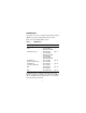
Introduction This guide shows how to install media dependent adapters (MDAs) into supported Nortel Networks* products. Table 1 lists the available MDA models. Table 1.
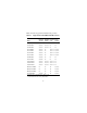
Table 2 lists the supported Nortel Networks products. Table 2. 1 2 Supported Products/Minimum SW Versions Model BayStack 3501/450 Business BayStack Passport Policy 410-24T 8132 Switch2 400-4TX MDA Yes/V1.0 Yes/V1.0 No No 400-2FX MDA Yes/V1.0 Yes/V1.0 No No 400-4FX MDA Yes/V1.3 Yes/V1.3 No No 450-1SR MDA Yes/V1.0 No Yes/V1.0 Yes/V1.0 450-1SX MDA Yes/V1.0 No Yes/V1.0 Yes/V1.0 450-1LR MDA Yes/V1.0 No Yes/V1.0 Yes/V1.0 450-1LX MDA Yes/V1.0 No Yes/V1.0 Yes/V1.
Note: The MDAs are not hot-swappable. Power down the BayStack switch or disconnect the Passport 8132 module from the switch backplane before installing or removing an MDA. 10BASE-T/100BASE-TX MDAs This section describes three 10BASE-T/100BASE-TX MDA models. The three models can support various product lines (see Table 2 on page 2 for a complete list of supported product lines). For installation instructions, see “Installing an MDA” on page 35.
If you connect to another Ethernet hub or Ethernet switch, you need a crossover cable unless an MDI connection exists on the associated port of the attached device. Figure 1 shows the 400-4TX MDA and the 8100-4TX MDA. 1 2 400-4TX MDA 100 10 F Dx Activity 400-4TX MDA 5 4 1 3 2 8100-4TX MDA 100 10 F Dx Activity 8100-4TX MDA 5 4 3 BS45042B Figure 1.
The 10BASE-T/100BASE-TX MDA ports can operate at either 10 Mb/s or 100 Mb/s. The port speed is determined through autonegotiation with its connecting device. Table 3 describes the 400-4TX MDA and the 8100-4TX MDA front-panel components. Table 3. 400-4TX / 8100-4TX MDA Item Label Description 1 100 100BASE-TX port status LEDs (green): On: The corresponding port is set to operate at 100 Mb/s. Off: The link connection is bad or there is no connection to this port.
Table 3. 400-4TX / 8100-4TX MDA (continued) Item Label Description 3 F Dx Full-duplex port status LEDs (green): On: The corresponding port is in full-duplex mode. Off: The corresponding port is in half-duplex mode. 4 Activity Port activity LEDs (green): Blinking: Indicates the network activity level for the corresponding port. A high level of network activity can cause LEDs to appear to be on continuously. 5 10BASE-T/100BASE-TX RJ-45 (8-pin modular) port connectors.
Table 4 describes the BPS2000-4TX MDA front-panel components. Table 4. BPS2000-4TX MDA Item Label Description 1 10/100 10BASE-T/100BASE-TX port status LEDs: On (green): The corresponding port is set to operate at 100 Mb/s. On (yellow): The corresponding port is set to operate at 10 Mb/s. Off: The link connection is bad or there is no connection to this port. 2 Activity Port activity LEDs (green): Blinking (green): Indicates the network activity level for the corresponding port.
0BASE-FX MDAs Warning: Fiber optic equipment can emit laser or infrared light that can injure your eyes. Never look into an optical fiber or connector port. Always assume that fiber optic cables are connected to a light source. Vorsicht: Glasfaserkomponenten können Laserlicht bzw. Infrarotlicht abstrahlen, wodurch Ihre Augen geschädigt werden können. Schauen Sie niemals in einen Glasfaser-LWL oder ein Anschlußteil. Gehen Sie stets davon aus, daß das Glasfaserkabel an eine Lichtquelle angeschlossen ist.
Avvertenza: Le apparecchiature a fibre ottiche emettono raggi laser o infrarossi che possono risultare dannosi per gli occhi. Non guardare mai direttamente le fibre ottiche o le porte di collegamento. Tenere in considerazione il fatto che i cavi a fibre ottiche sono collegati a una sorgente luminosa. This section describes the six 100BASE-FX MDA models (three dual-port and three quad-port models).
Dual-Port 100BASE-FX Models The three dual-port models are: • 400-2FX MDA Not supported on the Business Policy Switch and Passport 8132. • 8100-2FX MDA Supports BayStack 350/450, BayStack 410, and Passport 8132 Modules. • BPS2000-2FX MDA Supports the Business Policy Switch. The three dual-port 100BASE-FX MDA models each use two longwave 1300 nm SC connectors to attach devices over 62.5/125 micron multimode fiber optic cable. Figure 3 shows the 400-2FX MDA and the 8100-2FX MDAs.
1 2 400-2FX MDA 100BASE-FX 100BASE-FX Link F Dx Activity TX RX TX RX 400-2FX MDA 3 4 1 2 8100-2FX MDA 100BASE-FX 100BASE-FX Link F Dx Activity TX RX TX RX 8100-2FX MDA 3 4 BS45071A Figure 3. 400-2FX and 8100-2FX MDAs Table 5 describes the 400-2FX MDA and the 8100-2FX MDA front-panel components.
Table 5. 400-2FX MDA / 8100-2FX MDA Description Item Label Description 1 Link Communications link LEDs (green): On: Valid communications link. Off: Invalid communications link or no connection to this port. Blinking: The corresponding port is management disabled. 2 F Dx Full-duplex port status LEDs (green): On: The corresponding port is in full-duplex mode. Off: The corresponding port is in half-duplex mode.
Figure 4 shows the BPS2000-2FX MDA. BPS2000-2FX MDA 1 BPS2000-2FX MDA 2 3 BPS20001A Figure 4. BPS2000-2FX MDA Table 6 describes the BPS2000-2FX MDA front-panel components. Table 6. BPS2000-2FX MDA Description Item Label Description 1 Link Link status LEDs (green): On (green): Valid 100 Mb/s communications link. Off: No link activity.
Table 6. BPS2000-2FX MDA Description (continued) Item Label Description 2 Activity Port activity LEDs (green): On: Indicates the network activity level for the corresponding port. A high level of network activity can cause LEDs to appear to be on continuously. Off: No activity. 3 100BASE-FX port connectors: The BPS2000-2FX MDA uses SC connectors. Quad-Port 100BASE-FX Models The three quad-port models are: • 400-4FX MDA Not supported on the Business Policy Switch or Passport 8132.
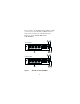
Figure 5 shows the 400-4FX MDA and the 8100-4FX MDA. 1 400-4FX MDA Link 2 F Dx Activity 400-4FX MDA 3 4 1 8100-4FX MDA Link 2 F Dx Activity 8100-4FX MDA 3 4 BS45072A Figure 5. 400-4FX and 8100-4FX MDAs Table 7 describes the 400-4FX MDA and the 8100-4FX MDA front-panel components.
Table 7. 400-4FX MDA / 8100-4FX MDA Description Item Label Description 1 Link Communications link LEDs (green): On: Valid communications link. Off: Invalid communications link or no connection to this port. Blinking: The corresponding port is management disabled. 2 F Dx Full-duplex port status LEDs (green): On: The corresponding port is in full-duplex mode. Off: The corresponding port is in half-duplex mode.
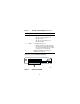
Figure 6 shows the BPS2000-4FX MDA. BPS2000-4FX MDA 1 BPS2000-4FX MDA 3 Figure 6. 2 BPS20002A BPS2000-4FX MDA Table 8 describes the BPS2000-4FX MDA front-panel components. Table 8. BPS2000-4FX MDA Description Item Label Description 1 Link Link status LEDs (green): On (green): Valid 100 Mb/s communications link. Off: No link activity.
Table 8. BPS2000-4FX MDA Description (continued) Item Label Description 2 Activity Port activity LEDs (green): On: Indicates the network activity level for the corresponding port. A high level of network activity can cause LEDs to appear to be on continuously. Off: No activity. 3 100BASE-FX port connectors: The BPS2000-4FX MDA uses MT-RJ connectors.
1000BASE-X MDAs Warning: This is a Class 1 Laser/LED product. It contains a laser light source that can injure your eyes. Never look into an optical fiber or connector port. Always assume that the fiber optic cable or connector is connected to a laser light source. Vorsicht: Dieses Laser/LED-Produkt der Klasse 1 enthält eine Laserlichtquelle, die zu Augenverletzungen führen kann. Sehen Sie nie in einen Lichtwellenleiter oder Glasfaserstecker-Port.
Avvertenza: Questo è un produtto laser/LED di Classe 1 e contiene una sorgente luminosa a laser che può danneggiare gli occhi. Non guardare mai all’interno di una port a fibra ottica o di una porta connettore. Dare sempre per scontato che il cavo di fibra ottica o il connettore siano collegati ad una sorgente luminosa a laser.
Shortwave Gigabit Models The two 1000BASE-SX (shortwave gigabit) MDA models are: • 450-1SR MDA -- single MAC MDA with a separate redundant Phy (backup Phy port). Only one Phy port can be active at any time. If the active Phy port fails, the redundant Phy port automatically becomes the active port. • 450-1SX MDA -- single PHY MDA. Both models conform to the IEEE 802.3z 1000BASE-SX standard and use shortwave 850 nm fiber optic connectors to connect devices over multimode (550 m/1805 ft) fiber optic cable.
1 450-1SR MDA (1-port redundant) 1000BASE-SX 2 1000BASE-SX Link Phy Select Activity TX RX TX RX 450-1SR MDA 3 4 1 450-1SX MDA (single port) 2 1000BASE-SX Link Phy Activity TX RX 450-1SX MDA 3 4 BS45044A Figure 7.
Table 9 describes the 450-1SR MDA and the 450-1SX MDA front-panel components. Table 9. 450-1SR / 450-1SX MDA Description Item Label Description 1 Link Communication link LEDs (green): On: Valid communications link. Off: The communications link connection is bad or there is no connection to this port. Blinking: The corresponding port is management disabled. 2 Phy (or) Phy Select Phy status LEDs (green): On: The corresponding Phy port is active.
Longwave Gigabit Models The two 1000BASE-LX (longwave gigabit) MDA models are: • 450-1LR MDA -- single MAC MDA with a separate redundant Phy (backup Phy port). Only one Phy port can be active at any time. If the active Phy port fails, the redundant Phy port automatically becomes the active port. • 450-1LX MDA -- single Phy MDA. Both models conform to the IEEE 802.3z 1000BASE-LX standard and use longwave 1300 nm fiber optic connectors to connect devices over single mode (5 km/3.
1 450-1LR MDA (1-port redundant) 1000BASE-LX 2 1000BASE-LX Link Phy Select Activity TX RX TX RX 450-1LR MDA 3 4 1 450-1LX MDA (single port) 2 1000BASE-LX Link Phy Activity TX RX 450-1LX MDA 3 4 BS45045A Figure 8. 450-1LR and 450-1LX MDA Front Panels Table 10 describes the 450-1LR MDA and the 450-1LX MDA front-panel components.
Table 10. 450-1LR and 450-1LX MDA Description Item Label Description 1 Link Communication link LEDs (green): On: Valid communications link. Off: The communications link connection is bad or there is no connection to this port. Blinking: The corresponding port is management disabled. 2 PHY (or) Phy Select Phy status LEDs (green): On: The corresponding Phy port is active. Off: The corresponding Phy port is in backup mode or there is no connection to this port.
ATM MDAs Warning: This is a Class 1 Laser/LED product. It contains a laser light source that can injure your eyes. Never look into an optical fiber or connector port. Always assume that the fiber optic cable or connector is connected to a laser light source. Vorsicht: Dieses Laser/LED-Produkt der Klasse 1 enthält eine Laserlichtquelle, die zu Augenverletzungen führen kann. Sehen Sie nie in einen Lichtwellenleiter oder Glasfaserstecker-Port.
Avvertenza: Questo è un produtto laser/LED di Classe 1 e contiene una sorgente luminosa a laser che può danneggiare gli occhi. Non guardare mai all’interno di una port a fibra ottica o di una porta connettore. Dare sempre per scontato che il cavo di fibra ottica o il connettore siano collegati ad una sorgente luminosa a laser. This section describes the two ATM MDA models (multimode and single-mode fiber models).
Both ports can be active at the same time. In the event of a port failure, traffic destined for the failed port can be set to automatically route to the remaining operational port (see “ATM Configuration Menu” in your switch’s User Guide). Both models use longwave 1300 nm fiber optic connectors to connect devices over single mode (10 km/6.2 mi) or multimode (2 km/1.2 mi) fiber optic cable. Figure 9 shows the 450-2M3 MDA and 450-2S3 MDA.
Table 11 describes the 450-2M3 MDA and 450-2S3 MDA front-panel components. Table 11. 450-2M3 and 450-2S3 MDA Description Item Label Description 1 Rx Receive Status: On steady (green): Valid communications link; no activity. On steady (yellow): No valid communications link. Off: The MDA is broken (or not fully seated in the slot). Blinking (green): Valid communications link; receive activity. 2 Tx Transmit Status: On steady (green): Valid communications link; no activity.
GBIC MDA Warning: This is a Class 1 Laser/LED product. It contains a laser light source that can injure your eyes. Never look into an optical fiber or connector port. Always assume that the fiber optic cable or connector is connected to a laser light source. Vorsicht: Dieses Laser/LED-Produkt der Klasse 1 enthält eine Laserlichtquelle, die zu Augenverletzungen führen kann. Sehen Sie nie in einen Lichtwellenleiter oder Glasfaserstecker-Port.
Avvertenza: Questo è un produtto laser/LED di Classe 1 e contiene una sorgente luminosa a laser che può danneggiare gli occhi. Non guardare mai all’interno di una port a fibra ottica o di una porta connettore. Dare sempre per scontato che il cavo di fibra ottica o il connettore siano collegati ad una sorgente luminosa a laser. This section describes the 450-1GBIC MDA: The 450-1GBIC MDA (see Figure 10) provides a single host port for supported Gigabit Interface Converters (GBICs).
1 2 450-1GBIC MDA GBIC Link Phy Activity 450-1GBIC MDA 3 4 GBIC model with extractor tabs GBIC model with extractor handle SC connector BS450102A Figure 10.
Table 12 describes the 450-1GBIC MDA front-panel components. Table 12. 450-1GBIC MDA Description Item Label Description 1 Link Communication link LEDs (green): On: Valid communications link. Off: The communications link connection is bad or there is no connection to this port. Blinking: The corresponding port is management disabled. 2 Phy Phy status LEDs (green): On: The corresponding Phy port is active. Off: The corresponding Phy port is in backup mode or there is no connection to this port.
Installing an MDA The Uplink/Expansion Module slot on supported switches can accommodate a single MDA. The connection can be either an RJ-45 10/100BASE-TX MDA or a fiber (100BASE-FX or 1000BASE-SX/LX) MDA with an SC or MT-RJ connector. Note: The MDAs are not hot-swappable. Power down the switch or disconnect the Passport 8132 module from the switch backplane before installing or removing an MDA. To install an MDA: 1.
1 2 Uplink/Expansion Module 25 26 27 28 100 10 F Dx Activity 400-4TX MDA 1 = Card guides 2 = Uplink module slot BS45059C Figure 11. 4. Installing an MDA Press the MDA firmly into the Uplink/Expansion Module slot. Be sure that the MDA is fully seated into the mating connector. 5. Secure the MDA by tightening the thumb screws on the MDA front panel.
6. Attach devices to the MDA ports. Refer to your switch’s User Guide for instructions on attaching devices to the MDA ports. After connecting the port cables, follow the instructions to connect power and verify the installation. Note: The IEEE 802.3u specification requires that all ports operating at 100 Mb/s use only Category 5 unshielded twisted pair (UTP) cabling. Replacing an MDA When replacing an installed MDA: 1. Power down the switch (or unplug the Passport 8132 module from the switch backplane).
Installing GBICs This section describes how to install the gigabit interface converters (GBICs) to your 450-1GBIC MDA’s Host port. The following optional GBIC versions are available to support your 450-1GBIC MDA: Table 13. Available GBIC Models Model number Description Part number 1000BASE-SX AA1419001 Uses shortwave 850 nm fiber optic connectors to connect devices over multimode (550 m/ 1805 ft) fiber optic cable.
The GBICs are available in different case styles (Figure 12). One type has two spring tabs at the front of the GBIC; the other type has an extractor handle on the front. GBICs are shipped with a protective rubber plug in the connectors. Leave the plug in place when no cables are connected to the GBIC. GBIC model with extractor tabs GBIC model with extractor handle 9702FA Figure 12.
To install a GBIC: 1. Remove the GBIC from its protective packaging. 2. Insert the GBIC into the Host port on the MDA (Figure 13). GBICs are keyed to prevent improper insertion. If the GBIC resists pressure, do not force it. Remove it, turn it over, and reinsert it. 9825FA Figure 13. Installing a GBIC 3. Press on the front of the GBIC until it snaps into place. 4. Remove the rubber plug to connect cables.
Removing an Installed GBIC To remove an installed GBIC: 1. If the GBIC has spring tabs, press in on the tabs on each side of the GBIC as you pull the GBIC out of the MDA’s Host port (Figure 14). 9826FA Figure 14. 2. Removing a GBIC If the GBIC has an extractor handle, grasp the handle and pull firmly to remove the GBIC from the MDA’s Host port.
1000BASE-LX Multimode Applications For 1000BASE-LX multimode applications, the longwave gigabit transceivers must be mode conditioned externally via a special offset SMF/MMF patch cord. The offset SMF/MMF patch cord allows the same transceiver to be used for both multimode and single-mode fiber. See your Nortel Networks sales representative for more information about the SMF/MMF patch cord.