Passport 4400 Hardware Installation Manual Part Number 211768, Rev.
Notice of Filing Declaration of CE Conformance (for International sales) A Declaration of CE Conformance is on file at the Nortel addresses shown below. The declaration lists the models described in this manual. If the unit carries the CE mark, this declaration certifies that it meets the specific EMC standards and safety (LVD) standards required for CE marking. If the product is a module, the module is CE-compliant only if it is placed in a CE-marked base unit.
Safety Warnings and Cautions Various safety agencies request statements of warning or caution to help you in the safe operation of the unit. These statements also apply to any and all modules installed within the unit. To ensure adequate cooling of the equipment a 2.0 inch unobstructed space must be maintained around all sides of the unit. Um die Kühlung des Gerätes nicht zu beschränken, ist es notwendig um das Gerät herum an allen Seiten ca 5 cm Raum zu lassen.
Notification of FCC Requirements NOTE: This equipment has been tested and found to comply with the limits for a Class A digital device, pursuant to Part 15 of the FCC Rules. These limits are designed to provide reasonable protection against harmful interference when the equipment is operated in a commercial environment.
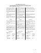
Contents Who Should Read this Document. . . . . . . . . . . . . . . . . . . . . . . . . . . . . . . . . . . . . . . . . . . . . . . ix Introduction — 1 Ethernet Base Module . . . . . . . . . . . . . . . . . . . . . . . . . . . . . . . . . . . . . . . . . . . . . . . . . . . . . . . Data Modules . . . . . . . . . . . . . . . . . . . . . . . . . . . . . . . . . . . . . . . . . . . . . . . . . . . . . . . . . . . . . . T1/E1 and Digital Voice Modules . . . . . . . . . . . . . . . . . . . . . . . . . . . .
Analog Voice Modules — 6 Single and Dual Channel Models . . . . . . . . . . . . . . . . . . . . . . . . . . . . . . . . . . . . . . . . . . . . . . . Analog Voice Module . . . . . . . . . . . . . . . . . . . . . . . . . . . . . . . . . . . . . . . . . . . . . . . . . . . . . . . . Universal Analog Voice Module . . . . . . . . . . . . . . . . . . . . . . . . . . . . . . . . . . . . . . . . . . . . . . . . Interface Modules . . . . . . . . . . . . . . . . . . . . . . . . . . . . . . . . . . . . . . . . . .
Setting the Switch Group . . . . . . . . . . . . . . . . . . . . . . . . . . . . . . . . . . . . . . . . . . . . . . . . . . . . . Stacking Connectors. . . . . . . . . . . . . . . . . . . . . . . . . . . . . . . . . . . . . . . . . . . . . . . . . . . . . . . . . Back Panel Grounding Clips . . . . . . . . . . . . . . . . . . . . . . . . . . . . . . . . . . . . . . . . . . . . . . . . . . . Spacers. . . . . . . . . . . . . . . . . . . . . . . . . . . . . . . . . . . . . . . . . . . . . . . . . . . . . . . .
viii
About this document This manual contains detailed information about the hardware components that make up the Passport 4430/4450/4455 device, hereafter referred to as a Passport 4400 unit. Each chapter in this manual contains information pertaining to a particular phase of installing, cabling, or overall operations of the Passport 4400.
Passport 4400 Hardware Installation Manual x About this document
Introduction 1 This chapter introduces the following features of the Passport 4430/4450/4455 devices, hereafter referred to as a Passport 4400 unit: • Ethernet Base Module on page 1-3 • Data Modules on page 1-3 • T1/E1 and Digital Voice Modules on page 1-4 • Analog Voice Modules on page 1-4 • Interface Modules (WAN) page 1-5 Models 4450 and 4455 Model 4430 Model 4450 and 4455 with Redundand Power Supply Figure 1-1.
Passport 4400 Hardware Installation Manual Introduction Passport 4400 units are multimedia, frame relay access devices deployed as an overlay to an existing Passport frame relay network. In this configuration, Passport 4400 units form distinct networks in which separate units communicate using switched virtual circuits (SVCs) provided by the Passport backbone.
Introduction Passport 4400 Hardware Installation Manual Ethernet Base Module The Ethernet Base Module performs central processing functions for the Passport 4400 unit. This module must be present in the lowest slot in the unit.
Passport 4400 Hardware Installation Manual Introduction T1/E1 and Digital Voice Modules T1/E1 and Digital Voice Modules are installed in the slots above the Ethernet Base Module (slots B, C, D, E).
Introduction Passport 4400 Hardware Installation Manual Refer to Chapter 6, Analog Voice Modules, for more detailed information concerning these modules. Interface Modules (WAN) Interface Modules for WAN are installed in Port2 and Port 3 on the Ethernet Base Module.
Passport 4400 Hardware Installation Manual 1-6 Introduction
Installing the Passport 4400 2 This chapter describes the procedures used to set up and connect a Passport 4400 unit (Passport 4430/4450/4455). Refer to the following manuals for relative information: • Using Passport 4400 Install Tool Version 4.
Passport 4400 Hardware Installation Manual Installing the Passport 4400 Allow 30.5 cm (12 inches), or greater, for access to rear 16.5 cm (6.5 inches) Allow 5.08 cm (2 inches), or greater, side space for air vents 30.5 cm* 44.5 cm (12 inches) (17.5 inches) *For DC models, add 5.72 cm (2.25 inches) for DC connector Figure 2-1. Space Requirements for a Standard 5-Slot Unit Allow 30.5 cm (12 inches), or greater, for access to rear Allow 5.08 cm (2 inches), or greater, side space for air vents 12.
Installing the Passport 4400 Passport 4400 Hardware Installation Manual Environmental Specifications Temperature - Operating: 0 to 50°C (32° to 122°F) Storage: -40° to 70°C (-40° to 158°F) Relative Humidity - Operating: 10% to 90% (non-condensing) Storage: 0% to 95% (non-condensing) Unpacking Your Passport 4400 Unit Follow the instructions below to unpack your Passport 4400 unit. 1. Read the labels on the box prior to opening the box. Note: Make sure that you keep the packing list included.
Passport 4400 Hardware Installation Manual Installing the Passport 4400 Passport 4400 Rack Installation 1. Install the clip nuts on the rack. 2. Place the shelf in the rack. 3. Secure both sides of the shelf to the rack, using the provided screws and washers (see Figure 2-4 below). 4. Position the unit on the rackmount shelf from the rear. Place the front of the unit through the cutout in the front of the rackmount shelf (see Figure 2-5 on page 2-5).
Installing the Passport 4400 Passport 4400 Hardware Installation Manual Rack-mounted 5-Slot Chassis Unit Passport 4450 Rack-mounted Unit with Redundant Power Supply Passport 4455 Rack-mounted 3-Slot Chassis Unit Passport 4430 Figure 2-5. Passport 4400 Unit in Rackmount Shelf Connecting an AC Unit ! Warning: Before the unit is turned on, make sure there is a separate ground wire connection between the unit chassis and input power source ground.
Passport 4400 Hardware Installation Manual Installing the Passport 4400 If an AC power cord is supplied with your unit, the power cord should be one of the following • A molded three-prong power cord with an appropriate connector to match the power outlet in your country, as shown in Figure 2-6 below. • A power cord with a two-prong power connector and a green-with-yellow stripe ground wire as shown in the examples in Figure 2-7 below.
Installing the Passport 4400 Passport 4400 Hardware Installation Manual Connecting a DC Unit ! Warning: Before applying power to the Passport 4400 unit, make sure that the unit is properly grounded. The DC version of the Passport 4400 unit has an external terminal block located on the back of the unit below the fan vents. A small black plastic door covers the terminal points. To access the terminal points, gently pull off the plastic door from the top with your finger.
Passport 4400 Hardware Installation Manual 2-8 Installing the Passport 4400
Ethernet Base Module 3 The Ethernet Base Module (EBM) performs central processing functions for any Passport 4400 unit (4430/4450/4455).
Passport 4400 Hardware Installation Manual Ethernet Base Module The Ethernet Base Module must be present in the lowest slot (A) for the unit to function. The remaining slots (B, C, D, E) house optional expansion voice or data modules as required. The figure below shows the rear view of a typical Passport 4450 unit. E D Optional Modules C B Ethernet Base Module Port 2 Port 3 Figure 3-2. Passport 4450 Unit - Rear View The Ethernet Base Module has six ports located on the back panel.
Ethernet Base Module Passport 4400 Hardware Installation Manual Port 2 and Port 3 are slots for optional plug-in Interface Modules supporting the following options: • 56 Kb/s CSU/DSU • T1 CSU/DSU • E1 CSU/DSU • ISDN U and S/T Interfaces • Serial WAN For more information on the interface modules, refer to Chapter 7, Interface Modules (WAN). Attaching Cables to the Ethernet Base Module The connections made in this procedure will depend on the specific site requirements.
Passport 4400 Hardware Installation Manual Ethernet Base Module Management Port The Management Port, located on the back panel of the Ethernet Base Module, allows you to connect the Passport 4400 unit to a Command Port (PC/CPU) or to a modem. The Management Port has the following functions: • Supports asynchronous operation using an RS-232/V.24 physical driver • Data rate is automatically selected for speeds from 9.6 to 38.4 Kb/s • Management port is RS-232/V.
Ethernet Base Module Passport 4400 Hardware Installation Manual Pin 1 50-Pin Connector 1, 2 Interface Type Indication 3, 28 V.35 Transmit Data 4, 29 V.35 External Receive Data Clock 5, 30 V.35 External Transmit Data Clock 6, 31 V.36/X.21 Transmit Data 7, 32 V.36/X.21 External Receive Clock 8, 33 V.36 External Transmit Clock/X.21 9, 34 RS-232/V.24/V.35/V.36 Clear to Send/ X.21 10, 35 RS-232/V.24/V.35/V.36 Data Set Ready 11, 36 RS-232/V.24/V.35/V.36 Carrier Detect 12 RS-232/V.24/V.
Passport 4400 Hardware Installation Manual Ethernet Base Module Ethernet Access Port The Ethernet Access Port (10BASE-T), located on the back panel of the Ethernet Base Module, connects the Passport 4400 to the Ethernet. Pin 1 RJ-45 RJ-45 Pin Assignments 1 (Tx+) Transmit Data Positive 2 (Tx-) Transmit Data Negative 3 (Rx+) Receive Data Positive To Ethernet 4 5 6 (Rx-) Receive Data Negative 7 8 Pins 4, 5, 7, 8 Not Connected Figure 3-6.
Ethernet Base Module Passport 4400 Hardware Installation Manual 16 Mbyte Flash Memory A 16 Mbyte Flash Memory SIMM (Passport 4430/4450 - NTBQ69AA, Passport 4455 - NTBQ70AA) must be installed for Release 2.0 and above software. This daughterboard contains the latest software configuration for the Passport 4400 unit and can be either factory installed or field upgradable. This SIMM is plugand-play and no jumper settings need to be altered. Figure 3-7.
Passport 4400 Hardware Installation Manual Ethernet Base Module 16 Mbyte DRAM The Passport 4400 offers an optional 16 Mbyte DRAM SIMM (NTAU95AA) offers an optional is needed for software version 3.1 and above. For instructions on removing and installing the SIMM, refer to Removing and Installing SIMMs on page 3-10. Figure 3-9. 16 Mbyte DRAM SIMM The correct E21 and E23 jumper block positions for the 16 Mbyte DRAM SIMM is 4M, (as opposed to 1M for the 8 Mbyte DRAM SIMM) as shown in Figure 3-10.
Ethernet Base Module Passport 4400 Hardware Installation Manual Data Compression The Data Compression feature (NTAU94AA for Release 4.0 and later) enhances the speed of the data supporting RFC1490 SVC and preconfigured RFC1490 PVCs. This SIMM is plug-and-play and no jumper settings need to be altered. Figure 3-11. Data Compression SIMM Note: Be sure you have the correct Ethernet Base Module (NTAU01BA or later version) before installing and using this feature.
Passport 4400 Hardware Installation Manual Ethernet Base Module Removing and Installing SIMMs Instructions for removing and installation are the same for the following SIMMs: • 16 Mbyte Flash Memory SIMM • 16 Mbyte DRAM SIMM • Data Compression SIMM Follow the procedure below to remove a SIMM in the Passport unit: 1. Gently push out the connector locking flanges located at each side of the slot housing the SIMM. 2. Move the SIMM to a vertical position. 3. Lift up the SIMM. 1. 3. 2.
Data Modules 4 This chapter describes the types of Data Modules available for your Passport 4400 unit (4430/4450/4455). These modules are defined as Legacy Data Modules and High-Speed Data Modules.
Passport 4400 Hardware Installation Manual Data Modules Legacy Data Module (6-Port and 6-Port with Tokin Ring) This module provides interface ports that support legacy data protocol in Passport 4400 units.
Data Modules Passport 4400 Hardware Installation Manual Legacy Data Expansion Module The Legacy Data Expansion Module (NTAU77AB) offers additional interface ports that support Legacy Data protocol in your Passport 4400 unit. Note: The connections will depend on the specific site requirements. If you are not sure of the exact connections required for the Passport 4400 unit, consult your system administrator. Use a 50-pin connector to join each serial data port to your local equipment.
Passport 4400 Hardware Installation Manual ! ! Caution: Data Modules Do not connect external cables until module installation is complete. When working inside the unit, be sure to take all precautions Warning: against electrostatic discharge. 1. Disconnect the power from the chassis. 2. Remove the cover. 3. Remove all cables from the Legacy Data Module that the Memory Expansion Module will be installed on. 4. Remove all modules above the Legacy Data Module. 5. Remove the Legacy Data Module.
Data Modules Passport 4400 Hardware Installation Manual Legacy Data Module Latching Posts Memory Expansion Module Module Switch Group (see Figure 10-1 on page 10-3) P16 IS P17 WD P18 BD P19 KD J11 Install Jumper on Position Marked P18 BD Figure 4-3.
Passport 4400 Hardware Installation Manual Data Modules Attaching Cables to the High-Speed Data Module Cable connections made in this procedure will depend on the specific site requirements. If you are not sure of the connections required for the Passport 4400 unit, consult your system administrator. For more information about cables, refer to Appendix A, Cable Diagrams.
T1, E1, and Digital Voice Modules 5 This chapter describes the hardware features and physical descriptions of the voice modules (digital) that provide the Passport 4400 unit (4430/4450/4455) with T1 or E1 connectivity and digital/analog voice options. Included are the following modules: • T1 Voice Module on page 5-2 — The Single Port T1 Voice Module (TVM/1 - NTAU99AA) provides connection to a single T1 line DS-1).
Passport 4400 Hardware Installation Manual T1, E1, and Digital Voice Modules T1 Voice Module The T1 Voice Module is available in a single (TVM/1E - NTAY99AA) or dual (TVM/2 - NTAY14AA) model. These modules provide an interface to one or two 1.544 Mbytes T1 lines (DS-1 for connection to T1 network services and DSX-1 to a local PBX).
T1, E1, and Digital Voice Modules Passport 4400 Hardware Installation Manual Connectors and Pin Assignments The figure below shows the connectors and pin assignments located on the backpanel of the T1 Voice Module. All pin assignments and other features are the same for single and dual port modules.
Passport 4400 Hardware Installation Manual T1, E1, and Digital Voice Modules E1 Voice Module The E1 Voice Module is available in a single (EVM/1) or dual (EVM/2) port module. The E1 Voice Module provides a user interface to one or two 2.048 Mbytes E1 lines, L1 interface, to a local PBX and a L2 interface for connection to E1 network services). The E1 Voice Module houses up to six Digital Voice Modules (DVMs).
T1, E1, and Digital Voice Modules Passport 4400 Hardware Installation Manual L2 (dual-port only) L1 Data Ports Pin 1 Pin 1 Receive Pair Same as Line 1 Transmit Pair For 75 ohms Interface See Figure 5-7, Figure 5-8, and Figure 5-9 DB-9 Connector For 120 ohms Balanced pair Interface 1 2 3 4 5 6 7 8 Tx Tip Rx Tip Pins 2, 4, 5, 7, 9 Not Connected Tx Ring Rx Ring Figure 5-4.
Passport 4400 Hardware Installation Manual T1, E1, and Digital Voice Modules The locations of the two impedance straps for line 1 are shown in the following figure. Line 1 75 ohms select. 120 ohms as shown. Figure 5-5. Location of the E1 Interface Line Straps Strapping for the 75 Ohm Outer Conductor The outer conductors of the 75 ohm BNC interface connectors may be connected to earth or isolated. Strapping is implemented by a set of headers and jumpers as shown in Figure 5-6 on page 5-6.
T1, E1, and Digital Voice Modules Passport 4400 Hardware Installation Manual Table 5-1. Outer Conductor Jumper Settings for the 75 Ohm Connector Connector To Earth Isolated (Open) Line 1 Rx (DSX-1) Place jumper over E83, pins 1 and 2. Place jumper over E83, pins 2 and 3.* Line 1 Tx (DSX-1) Place jumper over E78, pins 1 and 2.* Place jumper over E78, pins 2 and 3. Line 2 Rx (DS-1) Place jumper over E71, pins 1 and 2. Place jumper over E71, pins 2 and 3.
Passport 4400 Hardware Installation Manual T1, E1, and Digital Voice Modules Frame Ground 1 Send Data A (SD A) 2 Receive Data A (RD A) 3 Request-to-Send (RTS) 4 Clear-to-Send (CTS) 5 Data Set Ready (DSR) 6 Ground 7 Data Carrier Detect (DCD) 8 14 (SD B) Send Data 15 (SCT A) Serial Click Transmit A 16 (RD B) Receive Data B 17 (SCR A) Serial Clock Receive A 18 19 (SCR B) Serial Clock Receive B 20 (DTR) Data Terminal Ready 21 9 22 10 Unassigned (UNA) 23 (SCRE B) Serial Clock Rece
T1, E1, and Digital Voice Modules Passport 4400 Hardware Installation Manual Data Port Strapping Two data port connectors are located on both the T1 and the E1 access modules. The ports can be strapped for RS-232/V.24, V.35 or X.21 physical interface. Each connector is strapped by using two headers with jumpers located on the access modules. Note: Data ports can provide clocks up to 512 Kb/s. However, RS-232/V.24 strapped data ports are not recommended for speeds over 64 Kb/s. X.21 V.
Passport 4400 Hardware Installation Manual T1, E1, and Digital Voice Modules Digital Voice Expansion Module The Digital Voice Expansion Module (DVEM - NTAY18AA) is used to extend the number of voice channels supported by a T1 or E1 Voice Module. Each Digital Voice Expansion Module can accommodate up to a maximum of 12 additional Digital Voice Modules.
T1, E1, and Digital Voice Modules Passport 4400 Hardware Installation Manual Stacking Connectors Rear (Back Panel) Indicators Module Switch Group (see Figure 10-1 on page 10-3) Front Receptacles (12) for Digital Voice Modules Power Connector (see Figure 5-12 on page 5-12) Figure 5-11.
Passport 4400 Hardware Installation Manual T1, E1, and Digital Voice Modules Front View To DVEM TBD Rear To Power Sharing Board Do Not Connect Harness to a T1/E1 Voice Module DVEM TVM = T1 Voice Module EVM = E1 Voice Module DVEM = Digital Voice Expansion TVM/EVM Figure 5-12. DVEM Power Harness Digital Voice Module Digital Voice Module (DVM - NTAU60AA) is a daughterboards that fit into a slot on top of the T1/E1 Voice Module or the Digital Voice Expansion Module.
T1, E1, and Digital Voice Modules Passport 4400 Hardware Installation Manual Removing Daughterboards Follow the procedure below to remove or exchange a Digital Voice Module or any other daughterboard (SIMM). 1. Gently push out the connector locking flanges located at each side of the slot housing the daughterboard. 2. Move the daughterboard to a vertical position. 3. Lift up the daughterboard. 1. 3. 2.
Passport 4400 Hardware Installation Manual T1, E1, and Digital Voice Modules ISDN BRI Voice Module The ISDN BRI Voice Module (IVM-BRI/ST/2 - NTAU76CA) provides the Passport 4400 unit with ISDN interface for connection to an ISDN PBX, ISDN phone, or other ISDN protocol and provides external clocking capability. Note: The previous release of the modules (NTAU76AA and NTAU76BA) did not provide the BRI clock sync module for external clocking.
T1, E1, and Digital Voice Modules Passport 4400 Hardware Installation Manual To ensure that your unit is equipped with the External Synchronization feature, check the part number tag on the face plate of the Ethernet Base Module. All units shipped from the factory after January 2000 to non-North American locations will have this modification. The tag should read NTAU01CA Revision level 05 (or higher).
Passport 4400 Hardware Installation Manual 5-16 T1, E1, and Digital Voice Modules
Analog Voice Modules 6 Analog Voice Modules convert analog voice obtained from telephone interfaces into digital form, and internally connect the converted voice to the Ethernet Base Module within the unit. The following voice modules are discussed in this chapter: • Analog Voice Module on page 6-3. FXS, FXO, and E&M interfaces are determined by changing the straps on the front of the module’s circuit board.
Passport 4400 Hardware Installation Manual Analog Voice Modules Signaling Formats Use the information and figures below to ensure you are using the correct interfaces in your Analog Voice Modules. FXS • Provides ringing voltage and battery to the attached telephone equipment. • Selected when the voice channel is connected directly to a telephone instrument, to the trunk side of a key telephone system, or to the central office trunk of a Private Branch Exchange (PBX).
Analog Voice Modules Passport 4400 Hardware Installation Manual E&M • Used in a tie-trunk environment, when the voice channel is connected to the trunk circuit of a PBX. • It may be strapped one of three ways to select one of three E&M formats (Types I, II/IV, or V). When the Telephone Interface is: Trunk Side Station Side PBX Use Voice Channel E&M Figure 6-4.
Passport 4400 Hardware Installation Manual Analog Voice Modules Strapping Strapping involves matching the voice/fax channel with the attached telephone interface. Specifically, the voice/fax channel may be strapped, depending on the application, for one of three common types of signaling conventions: FXS (Foreign Exchange Station), FXO (Foreign Exchange Office), or E&M (Ear and Mouth). Analog Voice Modules installed in units are usually prestrapped to the interface type specified in the order.
Analog Voice Modules Passport 4400 Hardware Installation Manual Attaching Cables to the Analog Voice Module The connections will depend on the specific site requirements. If you are not sure of the exact connections required for the Passport 4400 unit you are installing, consult your system administrator. • If your site requires an E&M connection, use an RJ-48C cable to connect the Passport 4400 unit to a PBX.
Passport 4400 Hardware Installation Manual Analog Voice Modules Universal Analog Voice Module The Universal Analog Voice Module (UAVM) consists of two channels into which one of the four voice interface modules (E&M, FXO, FXS, or Voice/Fax Switch module), is inserted. The Universal Analog Voice Module must be configured with the correct jumper settings for the types of interface modules you plan to use before you can connect the modules to the network.
Analog Voice Modules Passport 4400 Hardware Installation Manual Interface Modules Interface modules are voice modules inserted in the slots provided on a Universal Analog Voice Module supporting FXS, FXO, E&M and Voice/Fax Switch modules. The type of interface module selected will depend on the signaling required (see page 6-2). Removing an Interface Module ! Caution: The interface module must not be inserted into, or removed from the unit, while the unit is operating.
Passport 4400 Hardware Installation Manual Analog Voice Modules Module Switch Group (see Figure 10-1 on page 10-3) Figure 6-11. Removing/Inserting an Interface Module Inserting an Interface Module ! Caution: The interface module must not be inserted into, or removed from the unit, while the unit is operating. This could cause damage to the unit or cause interruption of network services or both. 1. Place the interface module within the channel. 2.
Analog Voice Modules Passport 4400 Hardware Installation Manual ! Caution: When using the RJ-48C cable (NTMU88AA) supplied with the AVM, pin 1 (SB) on the lug end, has live -44 volts dc on it. If not used (such as in FXO or E&M Type I connections), make sure that the pin 1 (blue SB) lead is cut off and insulated with electrical tape to prevent contact with any object or equipment.
Passport 4400 Hardware Installation Manual Analog Voice Modules E&M Terminal Block Back Panel Of Interface Module 1 Secure Cable Leads Here (8 Places) Insert Cable Lead Here (8 places) Terminal Block Plug Left Tab Connector Cover Right Tab Terminal Block FXO and FXS 1 FXS Secure Cable Leads Here (4 Places) Insert Cable Lead Here (4 places) FXS FXS FAX Terminal Block PSTN PSTN 3-PORT Voice/Fax Switch Module Terminal Block Plug FAX Insert Cable Lead Here (8 places) Secure Cable Lead
Analog Voice Modules Passport 4400 Hardware Installation Manual FXS and FXO Interface Modules Except for the type designation, the FXS and FXO interface modules have identical telephone interface connectors on the back panel. Each consists of an RJ-11 modular jack labeled FXS or FXO and a 4-pin terminal block; see Figure 6-13 below. Both are shielded by a protective cover. ! Caution: The interface module must not be inserted into, or removed from the unit, while the unit is operating.
Passport 4400 Hardware Installation Manual Analog Voice Modules FXS Interface Strapping There are a total of six movable straps located on the FXS interface module, E1 through E6. These straps are reserved for factory use only. They must not be altered by the user. E2 Jumper out Jumper in (default) E1 S/N E6 E5 E4 E3 Figure 6-14.
Analog Voice Modules Passport 4400 Hardware Installation Manual FXO Interface Strapping The FXO interface is designed to meet regulatory agency requirements unique to selected countries (such as Spain, France, and Germany). This module contains special straps that implement the requirements of each country. There are 13 movable straps located on the FXO interface module, E1 through E13. The following four figures show the locations of these straps.
Passport 4400 Hardware Installation Manual Analog Voice Modules Country-specific Strap Settings ! Caution: The following figures give specific instructions on strapping the FXO Interface Module for use in Spain, France, Germany and Switzerland. The module is factory shipped with a default setting that operates correctly in all other countries. If this module is NOT to be used in one of the countries listed above, do not adjust the straps. France • Locate the strapping block labeled E6/E7.
Analog Voice Modules Passport 4400 Hardware Installation Manual Spain • Locate the strapping block labeled E8/E9. Place the strap over the pins marked E8 • Locate the strapping block labeled E10/E11. Place the strap over the pins marked E11 • Leave other strapping blocks (E6/E7, E13/E14, E15/E16) in their default positions E6/E7* E13/E14* E8/E9 E15/E16* E10/E11 Jumper in *Default setting Jumper out Figure 6-17.
Passport 4400 Hardware Installation Manual Analog Voice Modules Germany and Switzerland Locate the strapping block labeled E15/E16. Place the strap over the pins marked E15. Leave other strapping blocks (E6/E7, E8/E9, E10/E11, E13/E14) in their default positions. E6/E7* E13/E14* E8/E9* E15/E16* E10/E11* Jumper in *Default setting Jumper out Figure 6-18.
Analog Voice Modules Passport 4400 Hardware Installation Manual E&M Interface Module The E&M Interface Module telephone interface signals are terminated in an 8-pin tie trunk terminal block on the back panel (see Figure 6-19 below). This connector is fitted with a female plug. Individual cable leads are connected to this plug to form a telephone interface cable.
Passport 4400 Hardware Installation Manual Analog Voice Modules Strap Number Description E1 through E5 Reserved for factory use only. They must not be altered by the user. E16 Used to shut out the series resistor in the SB lead in case the loop resistance is too high to trip the detector inside the interface module. If cabling is short, try with the strap removed. E18 and E19 Reserved for factory use only. They must not be altered by the user. E20, E21, and E22 Spares.
Analog Voice Modules Passport 4400 Hardware Installation Manual Voice/Fax Switch Module There are four interface connectors available on the back panel of the Voice/Fax Switch Module (NTAU52AA), as shown in Figure 6-21 below. Three are modular RJ-11 jacks labelled FXS, FAX, and PSTN, respectively. The fourth is an 8-pin terminal block.
Passport 4400 Hardware Installation Manual Analog Voice Modules Figure 6-22 is a wiring diagram of the interface connectors. Note that the 8-pin terminal block is connected in parallel with the three modular RJ-11 connectors (pins 3 and 4 are not used). FXS FAX PSTN 2 2 2 3 3 3 RP TP RF TF 8 7 6 5 R 2 T 1 Figure 6-22. Interface Connection Wiring Diagram Strapping and PROM Orientation There are a total of five movable straps located on the Voice/Fax Switch Module, E1 through E5.
Interface Modules (WAN) 7 Interface Modules are WAN modules specifically designed to enhance the WAN capabilities of the unit.
Passport 4400 Hardware Installation Manual Interface Modules (WAN) WAN Serial Interface Module The WAN Serial Interface Module (NTAU03AA) provides additional port capability, identical to Port 1 on the base module. The module supports RS-232/ V.24, V.35, V.36, and X.21 interfaces, determined by the cable used. The module can support both DTE and DCE modes.The WAN serial interface module can be placed in Port 2 or Port 3.
Interface Modules (WAN) Passport 4400 Hardware Installation Manual Pin 1 RJ-48 RJ-48 Pin Assignments 1 2 3 4 5 6 7 8 Transmit data to Network Transmit data to Network Pins 3, 4, 5, 6 Not Connected Receive data from Network Receive data from Network Figure 7-3.
Passport 4400 Hardware Installation Manual Interface Modules (WAN) Pin 1 RJ-48 RJ-48 Pin Assignments 1 2 3 4 5 6 7 8 Receive Data from Network Receive Data from Network Transmit Data to Network Transmit Data to Network Pins 3, 6, 7, 8 Not Connected Figure 7-4. T1 CSU/DSU Interface Module, Connector, and Pin Assignments E1 CSU/DSU Interface Module An E1 CSU/DSU Interface Module provides a direct E1 or fractional E1 connection to a Passport E1 Function Processor, or any other compatible device.
Interface Modules (WAN) Passport 4400 Hardware Installation Manual E1 CSU/DSU Interface Module (120 ohms) The interface module must be inserted into the unit with the component side facing down. An 8-pin RJ-48C jack is provided to interface with the E1 network. Pin 1 RJ-48 RJ-48 Pin Assignments 1 2 3 4 5 6 7 8 Receive Data from Network Receive Data from Network Transmit Data to Network Transmit Data to Network Pins 3, 6, 7, 8 Not Connected Figure 7-5.
Passport 4400 Hardware Installation Manual Interface Modules (WAN) ISDN TA Interface Modules The ISDN (integrated services digital network) basic rate interface (BRI) plugin modules will be used as primary network link connections to the WAN or for backup in case of failure. ISDN interface modules may be placed in both Port 2 and Port 3. There are two types of ISDN TA interface modules: • ISDN TA U Interface (NTAU05AA) • ISDN TA S/T Interface (NTAU06AA) Both are accessed via an RJ-45 connector.
Interface Modules (WAN) Passport 4400 Hardware Installation Manual ISDN TA S/T Interface Module There are two user-adjustable straps on the ISDN TA S/T interface module, E3 and E4. These straps are used to configure the ISDN connection. Both straps are set to the factory default of OUT. Note: Refer to Appendix B, Regulatory and Telephone Company Requirements for agency and telephone company requirements.
Passport 4400 Hardware Installation Manual 7-8 Interface Modules (WAN)
Indicators 8 This chapter describes the status indicator lights (LEDs) of the Passport 4400 (4430/4450/4455). The indicators can be seen through a series of small windows located at the front of the unit. Indicators Figure 8-1.
Passport 4400 Hardware Installation Manual Indicators Table 8-1.
Indicators Passport 4400 Hardware Installation Manual Digital Voice Channel Status Indicators Indicators 1 through 6 represent, respectively, the status of the digital voice channels B1 through B6, as follows: Table 8-2.
Passport 4400 Hardware Installation Manual Indicators T1 and E1 Status Indicators Table 8-3. T1 Operational States Indicator Function State Status AT System Status Off Initialization mode – see Table 8-5. Green Operational mode Flashing green Download active. Off Interface not active. Flashing red Red alarm – sync loss (an out of frame condition) that lasts for more than 2.5 seconds. Flashing amber Yellow alarm – received from the remote node that is currently in the red alarm state.
Indicators Passport 4400 Hardware Installation Manual Table 8-4.
Passport 4400 Hardware Installation Manual Indicators Digital Voice Expansion Module There are 13 indicators associated with the Digital Voice Expansion Module, as shown below. 12 11 10 9 8 7 6 5 4 3 2 1 OK Figure 8-4. Digital Voice Expansion Module Indicators Table 8-6.
Indicators Passport 4400 Hardware Installation Manual Analog Voice Module and Universal Analog Voice Module There are a total of six indicators associated with each voice/fax channel of both the Analog Voice Module and the Universal Analog Voice Module. The following figure shows and describes the functions of the indicators during normal operation. Note: During network code download, each red indicator is turned on and off sequentially for 1 second.
Passport 4400 Hardware Installation Manual Indicators ISDN BRI Voice Module The ISDN BRI Voice Module has three indicators (LEDs) located at the front of the unit. These indicators are shown and described in the table below. B2 B1 D1 Figure 8-6. BRI Voice Module Indicators Table 8-8. BRI Voice Module Indicator Functions Indicator Function 8-8 Blinks On Off B2 Green indicator associated with B-channel 2.
Power Supplies 9 This chapter discusses the power supplies available for the following Passport units: • 3-slot Chassis power supply (Passport 4430 AC, page 9-1) • 5-slot Chassis power supply (Passport 4450 AC/DC and Passport 4455 AC/ACR, page 9-2) • 5-slot Redundant power supply (Passport 4450 ACR/DCR, page 9-3) 3-slot Chassis The 3-slot Passport 4430 chassis uses a 135 W AC power supply to provide power to the Ethernet Base Module and expansion modules.
Passport 4400 Hardware Installation Manual Power Supplies 5-slot Chassis The five-slot Passport 4450 chassis uses a 160W power supply to provide power to the Ethernet Base Module and expansion modules. Both AC and DC models are available; the figure below shows an AC unit. Input Connectors for DC Unit (side of power supply) Jumper J12 POS8 Status Cable Input Connectors for AC Unit POS1 Connector for DVEM Power Harness Power Cable (to Ethernet Base Module) Grounding Cable Figure 9-2.
Power Supplies Passport 4400 Hardware Installation Manual 5-slot Chassis with Redundant Power Supply A 5-slot Passport 4450 chassis with the redundant power supply option contains a subassembly that houses an extra power supply in the event that one of the original four fails. This unit is available in either AC and DC power; the figure below shows an AC unit.
Passport 4400 Hardware Installation Manual Power Supplies DC Power Supplies The DC power supply system allows the Passport 4400 unit to be installed in a telephone company environment with the necessary DC power input being furnished by the telephone company to the input of the Passport 4400 unit. Note: The Input Connectors on the DC power supply are located at the side of the power supply closest to the edge (see Figure 9-2 and Figure 9-3).
Power Supplies Passport 4400 Hardware Installation Manual Configuring the Power Supplies Note: The following information applies to five-slot Passport 4450 unit only. Three-slot Passport 4430 units do not need to be configured. The power supply at the bottom of the stack is called the master supply. All other supplies located above the master are called slave supplies. The five-slot models have one master and either three (4450 AC/DC) or four (4450 AC/ACR) slave power supplies.
Passport 4400 Hardware Installation Manual ! Caution: Notes: • Power Supplies Prior to turning on your unit, be sure to check the straps for proper positioning according to the particular unit you have. Incorrect strapping will cause the unit to malfunction. Jumper position one is strapped only when you have a redundant power supply installed.
General Installation 10 This section contains general installation information for all optional expansion modules for Passport 4400 units.
Passport 4400 Hardware Installation Module General Installation (TVM), an Analog Voice Module (AVM), and a High-Speed Data Module (HDM) would have the HDM in the first slot (physical slot B) above the EBM, followed by the TVM and the AVM (physical slots C and D). Modules must be stacked from bottom to top, without skipping a slot. Notes: • TVM/EVM must always be called LIM B regardless of its location in the stacking order • If you are using one HDM, it must always be in LIM 1 (physical slot B).
General Installation Passport 4400 Hardware Installation Module in its physical location and its logical location Note that even though the HighSpeed Data Module physically resides just above the Ethernet Base Module (in slot B), logically, its in LIM 1 (because the T1 Voice Module and Digital Voice Expansion Module must be in LIMs B, C and D).
Passport 4400 Hardware Installation Module General Installation Setting the Switch Group To set a switch to on, use a ballpoint pen or similar pointed tool and push the switch down. Take care that only one switch is on (down) and that the remaining three switches are off (up) (see Figure 10-2 below). Notice that each switch can represent either a numeric LIM or an alpha LIM, depending on the expansion module.
General Installation Passport 4400 Hardware Installation Module Back Panel Grounding Clips To ensure that the modules meet regulatory agency requirements, the grounding clips must not be removed from the back panel. Grounding Clips Spacers Spacers are attached to the inside of the front of the Passport 4400. They are used to secure the expansion modules inside the unit. Blank Back Panels Any open space not occupied by a module must contain a blank back panel.
Passport 4400 Hardware Installation Module General Installation Installing an Expansion Module Modules should be set for the appropriate application when they arrive from the factory. If changes need to be made to the module, such as setting jumpers or switches, refer to the appropriate section that specifically covers the module. To install an expansion module, us the following procedures. ! Caution: Modules cannot be inserted into or removed from the unit while the Passport 4400 unit is operating.
General Installation Passport 4400 Hardware Installation Module 6. Refer to Section 9, Power Supplies, to verify that the correct number of power supplies are configured for the number of modules used in the unit. 7. Strap the module, (refer to the section for the individual module). — Section 4, Data Modules — Section 5, T1, E1, and Digital Voice Modules — Section 6, Analog Voice Modules. 8. Set the module location switch group (see page 10-4). 9.
Passport 4400 Hardware Installation Module 10-8 General Installation
Connecting a Workstation 11 This chapter describes the requirements and procedures for establishing a direct or modem connection between a Passport 4400 unit and the workstation that you will use to manage that unit. Connecting the PC to the Passport 4400 Management Port You can connect the PC’s serial port to the Passport 4400’s Management Port, either directly or through a modem.
Variable Document_Name Connecting a Workstation Modem Connection If the PC and the Passport 4400 unit are not in physical proximity to one another, you can connect them through a modem, as shown in this diagram: PC Passport 4400 Serial Por t Management Port Serial Cable Modem Modem Null Modem NTAU17AA Figure 11-2.
Connecting a Workstation Variable Document_Name You can use a terminal emulation program or a dumb terminal to configure the modem. In either case, you must set the serial port baud rate to match that of the Passport 4400 management port (the default is 9600 baud). Use your modem documentation and the procedure that follows as a guide to configuring the modem. Procedure Using a Hayes-Compatible Modem To configure a Hayes-compatible modem for Quiet operations, follow these steps: 1.
Variable Document_Name Connecting a Workstation Procedure Using a US Robotics Sportster Series Modem The following is an example of modem configuration using a US Robotics Sportster Series Modem (other modems will be different, consult your modem manual). Configurating the modem requires hardware configuration (dip switches) and software configuration (AT commands). The chart below lists the hardware settings. Table 11-1.
Connecting a Workstation Variable Document_Name 4. Power the modem off and return the modem to dumb mode by setting hardware switch 8 to OFF (up). Connect the DB-25 end of the Passport 4460 management cable (NTAU17AA) to a null modem cable. Then connect the null modem cable to the US Robotics modem (see Figure 112 on page 11-2). ! Warning: Inaccurate modem settings and incorrect cabling may cause interruption of service on the Passport 4400 when attempting to dial in.
Variable Document_Name Connecting a Workstation Figure 11-3 displays a typical Ethernet connection. Passport 4400 LAN Port Network Interface Card Figure 11-3. Connecting a Passport 4400 Unit to the Ethernet Reset Switch A reset switch is located on the base module and can be accessed from the back of the unit, as shown below. Use a small, pointed object to press the reset switch through the hole in the back panel. The green reset indicator is also located on the base module next to the reset switch.
Cable Diagrams A Diagrams are shown in this section for cables used with the Passport 4400 (4430/ 4450/4455). Use the cable matrix to determine which cable must be used for the desired interface. Table A-1. Cable Selection for Ethernet Base Module and Data Modules Port Management Port Frame Relay Ports Type of Connector Interface CPC No. Engineering Connects to.... code Page No. RJ-45 RS232/V.24 A0668482 NTAU17AA DTE, M-M A-3 RJ-45 RS232/V.
Passport 4400 Hardware Installation Manual Cable Diagrams Table A-2. Cable Selection for T1, E1, and Digital Voice Modules Type of Connector Interface Port CPC No. Engineering code Connects to.... Page No. 56k CSU/DSU, RJ-45 straight A0670357 NTML79AA 4400 CSU/DSU Cable (RJ-45 to RJ-45) (14 ft.) A-18 T1 CSU/DSU E1 CSU/DSU RJ-48C crossover A0670698 NTMV09AA 4400 CSU/DSU Crossover Cable (RJ-45 to RJ-45) (14 ft.
Cable Diagrams Passport 4400 Hardware Installation Manual Pin 1 RJ-45 Male Ring Indicator 1 DB-25 Male 22 Carrier Detect 2 8 Data Terminal Ready 3 20 Ring Indicator Receive Line Signal Detector Data Terminal Ready Ground 4 7 Ground Receive Data 5 3 Receive Data Transmit Data 6 2 Transmit Data Clear to Send 7 5 Clear to Send Request to Send 8 4 Request to Send 25 To Passport Data Communication Add to Indicate 25-Pin Connector To Data Terminal Equipment (DTE) Figure A-1.
Passport 4400 Hardware Installation Manual RJ-45 Connector Cable Diagrams RJ-45 Connector RJ-45 Connector 1 1 2 2 3 3 4 4 5 5 6 6 7 7 8 8 Female DB-9 Connector RJ-45 Connector 1 1 2 2 Female DB-25 Connector 3 4 Data Transmit Ready 3 20 4 5 Signal Ground 4 7 Signal Ground 3 Receive Data 5 2 Receive Data 5 6 3 Transmit Data 6 2 Transmit Data Clear-To-Send 7 5 Clear-To-Send 7 8 8 8 To Passport 4400 To PC Serial Port To Passport 4400 To PC Serial Port
Cable Diagrams Passport 4400 Hardware Installation Manual 50-Pin Male 34-Pin V.
Passport 4400 Hardware Installation Manual Cable Diagrams 34-Pin V.
Cable Diagrams Passport 4400 Hardware Installation Manual 50-Pin Male 15-Pin X.
Passport 4400 Hardware Installation Manual Cable Diagrams 50-Pin Male 15-Pin X.
Cable Diagrams Passport 4400 Hardware Installation Manual 50-Pin Male Clear to Send 25-Pin RS-232 Male 9 5 Clear to Send Data Set Ready 10 6 Data Set Ready Carrier Detect 11 8 Carrier Detect Request to Send 12 4 Unassigned 13 11 Request to Send Unassigned Data Terminal Ready 37 20 Data Terminal Ready External Transmit Data Clock 40 24 Serial Clock Transmit External Transmit Data 16 2 Transmit Data Receive Data 41 3 Receive Data Transmit Data Clock 17 15 Serial Clock
Passport 4400 Hardware Installation Manual Cable Diagrams 50-Pin Male Clear to Send 9 25-Pin RS-232 Female 4 Request to Send Data Set Ready 10 20 Data Terminal Ready Carrier Detect 11 11 Unassigned Request to Send 12 5 Clear to Send Unassigned 13 8 Carrier Detect Data Terminal Ready 37 6 External Receive Clock 15 15 Serial Clock Transmit A External Transmit Clock 40 17 Serial Clock Receive A Transmit Data 16 3 Receive Data 41 2 Receive Data Clock 42 24 7 Signal Grou
Cable Diagrams Passport 4400 Hardware Installation Manual 50-Pin Male Clear to Send 9 25-Pin RS-232 Female 4 Request to Send Data Set Ready 10 20 Data Terminal Ready Carrier Detect 11 11 Unassigned Request to Send 12 5 Clear to Send Unassigned 13 8 Carrier Detect Data Terminal Ready 37 6 External Receive Clock 15 15 Serial Clock Transmit A External Transmit Clock 40 17 Serial Clock Receive A Transmit Data 16 3 Receive Data 41 2 Receive Data Clock 42 24 7 Signal Grou
Passport 4400 Hardware Installation Manual Cable Diagrams 50-Pin Male 37-Pin V.
Cable Diagrams Passport 4400 Hardware Installation Manual 50-Pin Male 37-Pin V.
Passport 4400 Hardware Installation Manual Cable Diagrams Receive Data A 20 37-Pin V.
Cable Diagrams Passport 4400 Hardware Installation Manual 50-Pin Male 37-Pin V.
Passport 4400 Hardware Installation Manual Cable Diagrams DB-15 Male 4 Receive Data A 50-Pin Male Receive Data A 20 Receive Data B Receive Data B 45 11 Transmit Data Clock A 21 14 Transmit Signal Element Timing A Transmit Data Clock B 46 7 Transmit Signal Element Timing B Receive Data Clock A 22 10 Receive Signal Element Timing A Receive Data Clock B 47 3 Receive Signal Element Timing B Transmit Data A 3 2 Transmit Data A Transmit Data B 28 9 Transmit Data B External Transmit
Cable Diagrams Passport 4400 Hardware Installation Manual 50-Pin Male 50-Pin Male Receive Data A 20 3 Transmit Data A Receive Data B 45 28 Transmit Data B External Receive Data Clock A 4 21 Transmit Data Clock A External Receive Data Clock B 29 46 Transmit Data Clock B Receive Data Clock A 22 5 External Transmit Data Clock A 47 30 External Transmit Data Clock B Transmit Data A 3 20 Receive Data A Transmit Data B 28 45 Receive Data B External Transmit Data Clock A 5 22 R
Passport 4400 Hardware Installation Manual Cable Diagrams DB-9 Connector (Male) DB-15 Connector (Female) Tip 1 (T1) 1 1 Tip (T) Ring 1 (R1) 6 9 Ring (R) Tip (T) 3 3 Tip 1 (T1) Ring (R) 8 11 Ring 1 (R1) To PBX or PSTN To E1 Voice Module Twisted Pair Twisted Pair Figure A-16.
Cable Diagrams Passport 4400 Hardware Installation Manual DB-9 Connector (Male) DB-15 Connector (Male) Tip 1 (T1) 1 3 Tip (T) Ring 1 (R1) 6 11 Ring (R) Tip (T) 3 1 Tip 1 (T1) Ring (R) 8 9 Ring 1 ( 1) Tip (T) R To PBX or PSTN To E1 Voice Module Twisted Pair Twisted Pair Figure A-18.
Passport 4400 Hardware Installation Manual Cable Diagrams Male Female Figure A-20. Coaxial Cable RJ-45 Connector RJ-11 Connector 1 1 Ring 2 2 Tip 3 3 4 4 Figure A-21. Cable NTMR38AA - Modular Straight Cable SB M R1 R T T1 E SG RJ-CX Connector Signal Battery (SB) 1 Mouth (M) 2 Ring 1 (R1) 3 Lug End and Wire Color SB, blue M, orange R1, black Ring (R) 4 R, red Tip (Tip) 5 T, green Tip 1 (T1) 6 T1, yellow Ear (E) 7 E, brown Signal Ground (SG) 8 DG, gray Figure A-22.
Regulatory and Telephone Company Requirements B This chaper describes the Regulatory Requirements and Telephone Company Requirements necessary for connecting to a telephone network and operating your Passport 4400 unit (4430/4450/4455). Regulatory Requirements Notice of Electromagnetic Compatibility (EMC) The following label certifies that, when installed in an approved chassis, the voice/fax module meets EMC Level A of the EN55022 Standard. This label is also affixed to the voice module.
Passport4400 Hardware Installation Manual Caution Achtung Avis To ensure adequate cooling of the equipment a 2.0 inch unobstructed space must be maintained around all sides of the unit. Um die Kühlung des Gerätes nicht zu beschränken, ist es notwendig um das Gerät herum an allen Seiten ca 5 cm Raum zu lassen. Pour assurer un refroidissement adéquat, maintenir un espace libre de 5 cm (2 pouces) tout autour de l’appareil.
Regulatory and Telephone Company Requirements Passport4400 Hardware Installation Manual Regulatory Compliances Safety UL 1950: up to A3 (1995) CSA Standard C22.2 No. 950: 1995 IEC 950: up to A3 (1995) TÜV: EN60950, up to A3 (1995) EN41003:1993 BABT 340 (where applicable):Seventh Edition (Manufacturing) Electromagnetic Compatibility FCC Part 15, Class A (T1 only) C.R.C.
Passport4400 Hardware Installation Manual Regulatory and Telephone Company Requirements T1 Voice Module (TVM) and E1 Voice Module (EVM) The following pertains to the T1 and E1 Voice Modules as part of the Passport 4400 unit.
Regulatory and Telephone Company Requirements Type of Interface: Connectors Provided: Facility Interface Code (FIC: Service Order Code: Passport4400 Hardware Installation Manual T1 1.544 digital interface with D4 framing format 1.544 digital interface with ESF framing format E1 2.048 Mbps digital interface T1 RJ-48C (2) E1 75 ohms BNC (4) 120 ohms DB-9 (1) T1 04DU9-BN 04DU9-DN 04DU9-1KN 04DU9-1SN E1 See individual interface 6.
Passport4400 Hardware Installation Manual Regulatory and Telephone Company Requirements Analog Voice Modules (AVM, UAVM) User’s Responsibility If a need arises in the future, the telephone company will call you and request the following information: • Manufacturer of the device: Nortel Networks • Model number of the device(s): Passport Description (see note) (for EU only) Name for Agency (EU) Analog Voice Module, single channel (AVM/1) NTAU61AA 5000CVM/1 Analog Voice Module, dual channel (AVM/2) 5
Regulatory and Telephone Company Requirements Passport4400 Hardware Installation Manual AVM E&M (CVM) USO Connector: Facility Interface Code: RJ-45CX • TL11M/E 2-Wire • TL12M/E 2-Wire • TL31M/E 4-Wire • TL32M/E 4-Wire AVM FXS (CVM) USO Connector: RJ-11C/W Facility Interface Code: OL13C 2-Wire Service Order Code: 9.0F AVM FXO (CVM) USO Connector: RJ-11C/W Facility Interface Code: O2LS2 2-Wire Service Order Code: 9.0F Ringer Equivalence: 0.
Passport4400 Hardware Installation Manual Regulatory and Telephone Company Requirements Interface Modules WAN Serial Interface Module The following pertains to the WAN Serial Interface Module as part of the Passport 4400 series. Telecommunication Requirements Compliant to CTR-2. 56kbps CSU/DSU Interface Module The following pertains to the 56 kbps CSU/DSU Interface Module as part of the Passport 4400 unit. User’s Responsibility This equipment is limited for use on 56kbps lines only.
Regulatory and Telephone Company Requirements Passport4400 Hardware Installation Manual T1 CSU/DSU Interface Module The following pertains to the T1 CSU/DSU Interface Module as part of the Passport 4400 unit. User’s Responsibility This equipment is limited for use on T1 Digital Service lines only.
Passport4400 Hardware Installation Manual Regulatory and Telephone Company Requirements ISDN TA U Interface Module The following pertains to the ISDN TA U Interface Module as part of the Passport 4400 unit. User’s Responsibility You must supply the following information upon request: • FCC Part 68 (U.S.A.
Regulatory and Telephone Company Requirements Passport4400 Hardware Installation Manual Telephone Company Requirements Repair Instructions If you experience trouble with this equipment, follow this procedure: 1. Determine whether the problem is your data terminal equipment. If you have another data terminal equipment, connect it in place of the inoperative unit to see if the data terminal equipment or the line is at fault. 2.
Passport4400 Hardware Installation Manual Regulatory and Telephone Company Requirements User’s Responsibility You must supply the following information upon request: • Whether the notification is about a connection or disconnection • The manufacturer of the device – Nortel Networks • Model number of the device: – Passport 4430AC: NTJ728AA – Passport 4450AC: NTJ729AA – Passport 4450ACR: NTJ730AA – Passport 4450DC: NTJ731AA – Passport 4450DCR: NTJ732AA Note: Agency approvals are for product Passport 4
Regulatory and Telephone Company Requirements Passport4400 Hardware Installation Manual Telephone Company Rights and Responsibilities (North America) If your data terminal equipment causes harm to the telephone network the telephone company may discontinue your service temporarily. If possible, they will notify you in advance. But if advance notice is not practical, you will be notified as soon as possible.
Passport4400 Hardware Installation Manual Regulatory and Telephone Company Requirements system, if present, are connected together. This precaution may be particularly important in rural areas. ! Caution: Users should not attempt to make such connections themselves, but should contact the appropriate electric inspection authority, or electrician, as appropriate. CP-01, Part I, Section 10.
Regulatory and Telephone Company Requirements Passport4400 Hardware Installation Manual AFFIDAVIT FOR CONNECTION OF CUSTOMER PREMISES EQUIPMENT TO 1.
Passport4400 Hardware Installation Manual B-16 Regulatory and Telephone Company Requirements
Specifications C Specifications Base Unit - Physical Dimensions 3-slot Unit Width Height Depth Weight 44.5 cm. (17.5 inches) 12.1 cm. (4.75 inches) 30.5 cm. (12.0 inches) 6.20 kg. (13.7 pounds) 5-slot Unit Width Height Depth Weight 44.5 cm. (17.5 inches) 16.5 cm. (6.5 inches) 30.5 cm. (12.0 inches) 7.75 kg. (17.1 pounds) 5-slot Unit with Redundant Power Supply Width Height Depth Weight 44.5 cm. (17.5 inches) 27.3 cm. (10.75 inches) 30.5 cm. (12.0 inches) 9.18 kg. (20.
Passport 4400 Hardware Installation Manual Specifications -12 volts/2 amperes max)24 watts) T1 Voice Module The following specifications pertain to the T1 Voice Module, dual port. Interfaces: 2; DS-1 (network) and DSX-1 (local) 1.544 digital interface with D4 framing format 1.544 digital interface with ESF framing format Connector: RJ-48C DS-1 (includes internal DSU/CSU) Number of DS0 Channels: 24 @ 64 kb/s Line Buildout: 0, -7.
Specifications Passport 4400 Hardware Installation Manual The following specifications pertain to the T1 Voice Module, single port. T1 Interface: DS-1 (network) With the exception of drop-and-insert and bypass, the single-port unit has the same capabilities as DS-1 interface of the dual port module. E1 Voice Module The following specifications pertain to the E1 Voice Module, dual port. Interfaces: 2; L1 (local) and L2 (network) 2.
Passport 4400 Hardware Installation Manual Specifications The following specifications pertain to the E1 Voice Module, single port. E1 Interface L1 (local) With the exception of drop-and-insert and bypass, the single-port E1 unit model has the same capabilities as the dual port model. Analog Voice Modules The following specifications are common to all FXS, FXO, and E&M interface types: Common Specifications Signals Supported: Analog voice and Group 3 facsimile Fax Signal Types: V.21 channel 2, V.
Specifications Passport 4400 Hardware Installation Manual Maximum Output Level: Longitudinal Balance 200 to 1004 Hz 1005 to 3404 Hz: Frequency Response Over the Range of 304 Hz to 3404 Hz: Idle Channel Noise Inband "C" Message: PSofometric: Out of Band, 10 KHz-10 MHz Transverse or Longitudinal Noise: +7 dB, E&M 4-wire enhanced only. All others 0 dB. >58 dB >48 dB +1 dB to -3 dB with respect to 1004 Hz for G.
Passport 4400 Hardware Installation Manual Specifications Telephone Interfaces PBX Tie Trunk: E&M Types I, II and V, 2-wire or 4-wire PBX Station or Central Office/PSTN: FXO Loop Start, 2-wire Key Telephone Systems, Telephone Set, or PBX CO Trunk: FXS Loop Start, 2-wire Interface Connectors Per Channel: RJ1CX modular jack for FXS and FXO type interfaces, and RJ1CX modular jack for E&M type interfaces Indicators per Channel: OK, Local Off-Hook, Remote Off-Hook, Local Speech, Remote Speech, and Tes
Specifications Passport 4400 Hardware Installation Manual FXS Signaling Specifications Signaling Formats AC: DC: DTMF Pulsed DTMF Distortion: <1.
Passport 4400 Hardware Installation Manual Specifications FXO Signaling Specifications Model 5000V/XOL Signaling Formats AC: DC: DTMF Pulsed TMF Distortion: 1<1.15% (transparently passed) Pulse Distortion: <3% DC Loop Range 48 V Battery: 42.5 V Battery: <1750 ohms <1500 ohms Disconnect Supervision Tone: Power Interrupt: Voice/fax transmission will be disconnected in response to a call progress tone of less than 600 Hz.
Specifications Passport 4400 Hardware Installation Manual ISDN BRI Voice Module The following specifications pertain to the ISDN BRI Voice Module. Interface Type: Basic Rate Interface (BRI) Number of Channels: 2 B-channels, 1 D-channel B-Channel: Each B-channel carries PCM-coded voice at a rate of 64 kb/s D-Channel: The D-channel carries signaling information for both B-channels at a rate of 16 kb/s.
Passport 4400 Hardware Installation Manual -10 Specifications
T1 Voice Module Cabling Requirements D The T1 Voice Module, like any other T1 device, uses two twisted wire pairs for connection to the T1 network. These wire pairs may include in-plant or oncampus wiring that is privately owned. In order to select wire pairs, consider the following: • A good system design separates the composite transmit and receive signals as much as possible.
Passport 4400 Hardware Installation Manual T1 Voice Module Cabling Requirements Shielded Cable Construction Typical telephone cable consists of plastic-coated pairs of 22- or 24-gauge wire (very seldom l9-gauge) with a mutual capacitance of 0.083 uF/mile. The cable should be in good repair, free of moisture, and have satisfactory transmission characteristics at 772 kHz (loss of less than -33-# dB and crosstalk of less than -63 dB).
T1 Voice Module Cabling Requirements Passport 4400 Hardware Installation Manual Shield Binder Group Shield Binder Group Binder Group 7-12 1-6 1-9 12-Pair 10-18 18-Pair Shield Binder Group Shield Binder Group Binder Group 1-12 1-12 38-50 13-25 26-37 13-25 50-Pair 25-Pair Shield Binder Group 63-75 Binder Group Shield Binder Group 13-25 51-62 1-25 76-100 26-50 51-75 26-37 1-12 38-50 75-Pair 100-Pair Binder Group Typical Telephone Type Shielded (Screened) Cable shield Fig
Passport 4400 Hardware Installation Manual T1 Voice Module Cabling Requirements Calculating Usable Cable Distance Usable cable distance varies as a function of wire gauge, insulation type, and temperature. Usable cable distance is also affected by the way transmit and receive pairs are assigned to binder groups, and by the number of systems operations in a binder group. Table D-1 lists maximum distances on exchange-grade (exterior) cables when both transmit and receive pairs are in the same binder group.
T1 Voice Module Cabling Requirements Passport 4400 Hardware Installation Manual Table D-1. Maximum Distance of Exchange-Grade Telephone Cable, With Transmit and Receive Pairs in the Same Binder Group Minimum Binder Size Maximum Distance in Feet (Loss in dB)* 18 pair 12 pair 6 pair 26 Awg 24 Awg 22 Awg 19 Awg 1 System ... ... 4220 (33) 5450 (32) 6530 (31) 8450 (29) 2 Systems 1 System ....
Passport 4400 Hardware Installation Manual D-6 T1 Voice Module Cabling Requirements
PBX Interface Connection Diagrams E Figures E-1 through E-3 show the circuit connections between an E&M voice channel and the PBX for signaling Types I, II, and V. PBX E&M Interface Type I M M GND SG DETECTOR AVM: E41, channel 1 E38, channel 2 UAVM: E14 -48 V DETECTOR E E * UAVM only: E15 T 2-Wire Operation R T 4-Wire Operation R T1 + R1 UAVM only: E8 + UAVM only: E17 * Install jumpers when cable distance to PBX is too long. Figure E-24.
Passport 4400 Hardware Installation Manual PBX Interface Connection Diagrams E&M Interface Type ll PBX UAVM only: E16 SB * SB - AVM: -44 V UAVM: -48 V + M M GND SG DETECTOR AVM: E41, channel 1 E38, channel 2 UAVM: E14 -48 V DETECTOR E E * T 2-Wire Operation R UAVM only: E15 T 4-Wire Operation R T1 + R1 UAVM only: E8 + UAVM only: E17 * Install jumpers when cable distance to PBX is too long. Figure E-25.
PBX Interface Connection Diagrams Passport 4400 Hardware Installation Manual E&M Interface Type V PBX SB** SB M M DETECTOR UAVM only: E16 * - AVM: -44 V UAVM: -42 V GND + SG AVM: E41, channel 1 E38, channel 2 UAVM: E14 DETECTOR E E * -48 V UAVM only: E15 T 2-Wire Operation R T 4-Wire Operation R T1 + R1 UAVM only: E8 + UAVM only: E17 * Install jumpers when cable distance to PBX is too long.
Passport 4400 Hardware Installation Manual E-4 PBX Interface Connection Diagrams
Index 120 Ohm E1 CSU/DSU Interface Module 7-5 16 Mbyte Flash Memory 3-7 56 kbps CSU/DSU Interface Module 1-5, 7- 2 agency compliances B-8 pin assignments 7-3 75 Ohm jumper settings 5-7 strapping 5-6 A AC Power connecting 2-6 cord 2-6 grounded 2-6 ungrounded 2-6 AC Unit Connections 2-5 Affidavit for Digital Services B-14 Agencies BABT iii, B-2 CSA iv FCC 2, iv TUV iii, B-2 UL iii, B-2 Agency Compliance 56 kbps CSU/DSU Interface Module B-8 user’s responsibility B-8 Analog Voice Module B-6 user’s responsibil
Analog Voice Modules Part Numbers see Chapter 1 AT Commands 11-2 B Back Panel blanks 10-5 grounding clips 10-5 Base Module see Ethernet Base Module C Cable Diagrams see Appendix A Cabling Requirements T1 Voice Module D-1 Calculating usable cable distance D-4 Canadian Requirements iv equipment attachment limitation B-13 CE Conformance 2 Configuring power supplies 9-5 Connecting AC unit 2-5, 2-6 Analog Voice Module 6-5 DC unit 2-7 E1 Voice Module 5-4 Ethernet Base Module 3-3 T1 Voice Module 5-2 terminal blo
ports 3-2 ports 2 and 3 3-3 56 Kb/s CSU/DSU 3-3 E1 CSU/DSU 3-3 ISDN U and S/T 3-3 Serial WAN 3-3 T1 CSU/DSU 3-3 rear view 3-2 Expansion Modules installation 10-1, 10-6 switches 10-4 F FCC Requirements iv, B-13 Foreign Exchange Office (FXO) 1-4 Foreign Exchange Station (FXS) 1-4 France 6-14 FXO impedances C-8 ringing detection C-8 specifications C-8 FXO Interface Module 6-11 strapping 6-13 France 6-14 Germany and Switzerland 6-16 Spain 6-15 FXS analog specifications C-7 impedances C-7 ringing cadence C-7 ri
75 ohm connector 5-7 L LED, see Indicators 8-1 Legacy Data Expansion Module 4-3 agency compliance B-10 connecting 4-3 Legacy Data Module 4-2 agency compliance B-10 Memory Expansion Module 4-3 pin assignments 4-2 LIM (Logical Interface Module) identifier 10-2 settings 10-2 Logical Interface Module switches 10-4 M Management Cable 11-2 Memory Expansion Module installation 4-3 Legacy Data Module 4-3 Modem Configuration 11-2 Modem Connection 11-2 Module Stacking Order 10-1 N Notice of Electromagnetic Compati
interface modules 6-7 Repair Instructions B-11 Reset Switch 11-6 location 11-6 Ringing Cadence FXS C-7 Ringing Detection FXO C-8 Ringing Frequency FXS C-7 S S/T Interface ISDN TA Interface Module 7-7 Safety Information iii, 10-1, B-1 Serial 1-5 Serial Interface Module agency compliance B-8 Shielded Cable Construction D-2 Signaling Formats C-6 SIMM 3-7, 5-12 Space Requirements Passport 4400 3-slot 2-2 5-slot redundant power supply 2-2 Spacers 10-5 Spain 6-15 Specifications C-1 agency compliance B-3 analog F
U Interface ISDN TA Interface Module 7-6 Universal Analog Voice Module 1-4, 6-6 E&M Interface Module 6-17 FCC registration B-7 FXS and FXO interface modules 6-11 indicators 8-7 interface modules 6-6 inserting 6-8 removing 6-7 terminal block 6-9 Unpacking Passport 4400 unit 2-3 Usable Cable Distance calculating D-4 User’s Responsibility 56 kbps CSU/DSU Interface Module B- 8 Analog Voice Module B-6 ISDN BRI Interface Module U interface B-10 T1 CSU/DSU Interface Module B-9 T1 Voice Module and E1 Voice Module
Passport 4400 Hardware Installation Manual for Passport 4430, Passport 4450, Passport 4455 Address comments to: Manager, Technical Publications Nortel Networks 4401 Great American Parkwayt Santa Clara, CA 95054 U.S.A. © 2001 Nortel Networks All rights reserved Information subject to change without notice Publication: 211768 Rev.