Nortel CallPilot 1005r Server Hardware Installation NN44200-308 .
Document status: Standard Document version: 01.06 Document date: 15 May 2008 Copyright © 2006-2008, Nortel Networks All Rights Reserved. Sourced in Canada The information in this document is subject to change without notice. The statements, configurations, technical data, and recommendations in this document are believed to be accurate and reliable, but are presented without express or implied warranty. Users must take full responsibility for their applications of any products specified in this document.
RADISYS is a trademark of Radisys Corporation. SLR4, SLR5, and TANDBERG are trademarks of Tandberg Data ASA. SYBASE is a trademark of Sybase, Inc. TEAC is a trademark of TEAC Corporation US ROBOTICS, the US ROBOTICS logo, and SPORTSTER are trademarks of US Robotics. WINZIP is a trademark of Nico Mark Computing, Inc. XEON is a trademark of Intel, Inc. All other trademarks and registered trademarks are the property of their respective owners.
Publication History May 2008 CallPilot 5.0, Standard 01.06 of CallPilot Installation and Configuration, 1005r Server Hardware Installation is issued for general release. May 2007 CallPilot 5.0, Standard 01.05 of CallPilot Installation and Configuration, 1005r Server Hardware Installation is issued for general release. April 2007 CallPilot 5.0, Standard 01.04 of CallPilot Installation and Configuration, 1005r Server Hardware Installation is issued for general release. April 2007 CallPilot 5.
Publication History Nortel CallPilot 1005r Server Hardware Installation NN44200-308 01.06 Standard 5.0 15 May 2008 Copyright © 2006-2008, Nortel Networks .
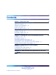
Contents Chapter 1 How to get help Chapter 2 1005r server description 9 11 1005r Server features 11 Valid PCI card configurations 16 Network connectivity 18 Supported peripheral devices 21 Chapter 3 Preparing for installation 23 Installation overview 23 Unpacking the 1005r server 25 Removing the front bezel 27 Chapter 4 Installing the server and peripheral devices 29 Installing the server 29 Inspecting the modem 31 Connecting peripherals to the server 31 Connecting the server to the ELAN subnet 3
Contents Nortel CallPilot 1005r Server Hardware Installation NN44200-308 01.06 Standard 5.0 15 May 2008 Copyright © 2006-2008, Nortel Networks .
Chapter 1 How to get help This section explains how to get help for Nortel products and services. Getting Help from the Nortel Web site The best way to get technical support for Nortel products is from the Nortel Technical Support Web site: www.nortel.com/support This site provides quick access to software, documentation, bulletins, and tools to address issues with Nortel products.
Chapter 1 How to get help www.nortel.com/erc Getting Help through a Nortel distributor or reseller If you purchased a service contract for your Nortel product from a distributor or authorized reseller, contact the technical support staff for that distributor or reseller. Nortel CallPilot 1005r Server Hardware Installation NN44200-308 01.06 Standard 5.0 15 May 2008 Copyright © 2006-2008, Nortel Networks .
Chapter 2 1005r server description In this chapter "1005r Server features" (page 11) "Valid PCI card configurations" (page 16) "Network connectivity" (page 18) "Supported peripheral devices" (page 21) "DCAM-7258188" (page 22) 1005r Server features Introduction The 1005r CallPilot server is a long life industrial server in a standard rack-mount 2U form factor. It utilizes dual Xeon technology and proven, reliable SCSI hard-drive technology.
Chapter 2 1005r server description Server dimensions and weight Height 87.6 mm (3.45 in.) Width 435.3 mm (17.4 in.) Depth (distance from front to back) 508 mm (20 in.) Weight of fully loaded system 20 kg (44 lb) Environmental specifications Environmental condition Specification Operating temperature 5 C to 35 C (41 F to 95 F) Maximum rate of change must not exceed 10 C (50 F) per hour.
1005r Server features 13 Front panel controls Label Control or feature Label Control or feature A Power switch L HDD1 activity B Reset switch M HDD0 activity C Critical alarm LED N DVD/CD/CDRW LED and eject button D Major alarm LED O Front serial port E Minor Alarm LED P USB 2 F Power Alarm LED Q Electrostatic Discharge (ESD) connection G NMI switch (not used) R Hard drive 1 pull handle H ID switch S Hard drive 1 release lever I ID LED T Hard drive 0 pull handle J
Chapter 2 1005r server description Back panel controls and features Label Control or feature Label Control or feature A DB15 Telco alarm connector (not used) G Rear connection to Comm 2 serial port B1 PCI card #3 dual NIC for High Availability (HA) configuration. For more information about HA, see High Availability: Installation and Configuration (NN44200-311). H RJ45 NIC 1 connector B2 PCI card #2 dual NIC for HA configuration.
1005r Server features 15 PCI riser card The following picture shows the PCI riser assembly when removed from the 1005r chassis. The PCI riser assembly is shown turned over with low-profile and full-size cards installed. Nortel CallPilot 1005r Server Hardware Installation NN44200-308 01.06 Standard 5.0 15 May 2008 Copyright © 2006-2008, Nortel Networks .
Chapter 2 1005r server description PCI riser card (turned over) CAUTION Risk of physical equipment damage Remove the 1005r from the rack, and place it on a solid surface when replacing or adding cards. The PCI riser assembly requires considerable force when inserting it into the connector, and physical damage can result if the assembly is not properly aligned.
Valid PCI card configurations 17 Note: Your server configuration depends on what was ordered from Nortel. Therefore, your server may not have all of the slots populated. When looking at the server from the rear (see "Back panel controls and features" (page 13)), both full-size and low-profile cards are numbered from the top down. Note: There are two MPB96 board versions; the NTRH40AA, and NTRH40CA. The following table compares the two boards.
Chapter 2 1005r server description Configuration Three MPB96 (High Capacity) Card slot type Slot number Position Card type Meridian 1*/ CS* 1000 Full size FS_PCI-1 top MPB96 MGate 1, 2, 3 FS_PCI-2 middle MPB96 MGate 4, 5, 6 FS_PCI-3 bottom MPB96 Note: 3 Mgate cards connect to 1 MPB96 When cabling to MGate cards, the RJ-45 connectors are numbered from 1 to 3 on the top NTRH40CA MPB96 board and from 4 to 6 on the middle NTRH40CA MPB96 board starting from the right side of the back panel
Network connectivity Sample network setup: Communication Server 1000 The following diagram shows a CallPilot server network setup with a Communication Server 1000 (CS 1000) system. Nortel CallPilot 1005r Server Hardware Installation NN44200-308 01.06 Standard 5.0 15 May 2008 Copyright © 2006-2008, Nortel Networks .
Chapter 2 1005r server description In the previous illustration, the telephony LAN (TLAN subnet) provides IP connectivity between the CS 1000 system and the i2004 Internet phonesets. The connection between the call server and media gateway can be point-to-point (or through the LAN), if the system is installed in a distributed data network.
Supported peripheral devices 21 Remote access connectivity Use one of the USB connectors on the rear of the 1005r server to connect to an external plug-and-play modem. The modem is used for remote administration and technical support. RRAS is used to establish the remote access connection to the server. Use either RDC or pcAnywhere to communicate with the CallPilot server. Supported peripheral devices Introduction This section identifies external devices that are supported by the 1005r server.
Chapter 2 1005r server description Nortel CallPilot 1005r Server Hardware Installation NN44200-308 01.06 Standard 5.0 15 May 2008 Copyright © 2006-2008, Nortel Networks .
Chapter 3 Preparing for installation In this chapter • "Installation overview" (page 23) • "Unpacking the 1005r server" (page 25) • "Removing the front bezel" (page 27) Installation overview Introduction This section provides an overview of the steps required to install the 1005r server and peripheral devices. Installation checklist The following checklist identifies the tasks that must be performed when installing the CallPilot server.
Chapter 3 Preparing for installation Step Description 2 Unpack the server, and ensure you have all the items you need (see "Unpacking the 1005r server" (page 25)). Check Complete the following checklists that are provided in the Installation and Configuration Task List (NN44200-306): • "CallPilot software media and documentation checklist" • "CallPilot server hardware checklist" 3 Remove the front bezel and inspect the front panel (see pages "Removing the front bezel" (page 27)).
Unpacking the 1005r server Step 7 Description 25 Check • Install the software feature dongle (see "Installing the Nortel software feature dongle" (page 37)). • Connect the power cords for all devices, and then power them up. Start the 1005r server (see "To start the server" (page 44)). Conventions for warnings You could encounter the following types of warnings in this guide. Do not ignore them.
Chapter 3 Preparing for installation WARNING Risk of personal injury The 1005r CallPilot server weighs approximately 20 kg (44 lb) when it is shipped from manufacturing. To prevent personal injury, have someone help you to unpack and position the server.
Removing the front bezel 27 Removing the front bezel Introduction To access the hard drives on the front panel, you must remove the front bezel. The front bezel covers the electrostatic discharge (ESD) connection, both hard drives, and the DVD/CD/CDRW drive pull handle. The control panel, USB port 2, and the front comm 2 serial port connection are not covered by the front bezel.
Chapter 3 Preparing for installation 3 Do not touch components on the front panel without ESD protection. Attach an ESD strap to your wrist and connect it to a single point ground connection. —End— What is next? Continue with Chapter 5 " Connecting the server to power" (page 41). Nortel CallPilot 1005r Server Hardware Installation NN44200-308 01.06 Standard 5.0 15 May 2008 Copyright © 2006-2008, Nortel Networks .
Chapter 4 Installing the server and peripheral devices In this chapter "Installing the server" (page 29) "Installing a High Availability system" (page 30) "Inspecting the modem" (page 31) "Connecting peripherals to the server" (page 31) "Connecting the server to the ELAN subnet" (page 35) "Connecting the server to the Nortel server subnet (optional)" (page 36) "Installing the Nortel software feature dongle" (page 37) Installing the server Introduction Before you install the 1005r server, ensure that th
Chapter 4 Installing the server and peripheral devices ATTENTION The 1005r server is supplied with industry standard 48.3 cm (19 in.) rack rails that can accommodate racks with a maximum depth of 61 cm (24 in.) between the mounting posts. Check the rack you are using and ensure that the Nortel supplied server rack rails are suitable for your specific installation requirements. For depths greater than 61 cm (24 in.
Connecting peripherals to the server • The two servers are delivered with only one dongle. It does not matter which server you connect the dongle to until you configure the servers. For more information about the High Availability feature, see High Availability: Installation and Configuration (NN44200-311). Inspecting the modem Introduction You require a modem to support remote dial-up access to the CallPilot server.
Chapter 4 Installing the server and peripheral devices Label Control or feature Label Control or feature B1 PCI card #3 dual NIC for HA configuration. For more information about HA, see High Availability: Installation and Configuration (NN44200-311). H RJ45 NIC 1 connector B2 PCI card #2 dual NIC for High Availability (HA) configuration. For more information about HA, see High Availability: Installation and Configuration (NN44200-311).
Connecting peripherals to the server 33 To connect the modem to the server Step Action 1 Connect one end of the telephone cable to the modem RJ-11 jack labeled LINE. 2 Connect the other end of the telephone cable to the RJ-11 jack in the wall. 3 Connect one end of the USB cable into the modem. 4 Connect the other end of the USB cable into either USB port 1 on the rear panel (long term) or USB port 2 on the front panel (short term).
Chapter 4 Installing the server and peripheral devices SLR75 tape drive installed on 1005r 6 The tape drive is plug-and-play and the required drivers are already installed on your system. 7 You must run the device scan initiation in device manager to detect the drive. a. Choose Start → My Computer →Properties →Hardware → Device Manager from the desktop. b. Select Action → Scan for Hardware changes. 8 The tape drive is ready for use.
Connecting the server to the ELAN subnet 35 Connecting the server to the ELAN subnet Introduction Connect the CallPilot server to the Meridian 1 switch or CS 1000 system using the ELAN subnet. Note: If you are installing a High Availability system, do not connect either sever to the ELAN subnet. The connection to the ELAN subnet is made when you configure the system. ATTENTION For important considerations about using the ELAN subnet in your network, see the Planning and Engineering Guide (NN44200-200).
Chapter 4 Installing the server and peripheral devices —End— What is next? IF the server is THEN connected to a Nortel server subnet continue with "Connecting the server to the Nortel server subnet (optional)" (page 36). not connected to a Nortel server subnet continue with installing the software feature dongle. See "Installing the Nortel software feature dongle" (page 37).
Installing the Nortel software feature dongle 37 What is next? Continue with "Installing the Nortel software feature dongle" (page 37). Installing the Nortel software feature dongle Introduction The software feature key is a security device that stores the unique serial number of the server. The feature key is embedded in the Nortel software feature dongle, which plugs into USB port 0 on the rear panel. Note: Only one dongle is shipped with a pair of High Availability servers.
Chapter 4 Installing the server and peripheral devices feature key with the data contact facing down and away from the embossed i. See "Installing the. feature key." (page 38). Dongle without feature key 3 To eject a software feature key, insert a straightened paper clip into the side access hole. a. Push the paper clip in the direction of the software feature key. Note: In the following figure, label 1 is the data contact, and label 2 is the ground. Installing the. feature key.
Installing the Nortel software feature dongle 39 What is next? Continue with Chapter 5 " Connecting the server to power" (page 41). Nortel CallPilot 1005r Server Hardware Installation NN44200-308 01.06 Standard 5.0 15 May 2008 Copyright © 2006-2008, Nortel Networks .
Chapter 4 Installing the server and peripheral devices Nortel CallPilot 1005r Server Hardware Installation NN44200-308 01.06 Standard 5.0 15 May 2008 Copyright © 2006-2008, Nortel Networks .
Chapter 5 Connecting the server to power In this chapter • "Safety precautions" (page 41) • "Locating the power supply modules" (page 41) • "About the power supply module" (page 42) • "Connecting the server to power" (page 42) Safety precautions Equipment handling guidelines External power equipment, such as an uninterruptible power supply (UPS), is usually very heavy. This equipment requires special handling procedures and additional personnel for unloading and installation.
Chapter 5 Connecting the server to power 1005r rear panel About the power supply module After you power up the server (later in this guide), the power supply module LED indicates its status. A green LED on each power supply module indicates that the modules are working properly. If the LEDs are unlit or red, the module is failing or has failed. A problem with a power supply module is also indicated if the PWR or MJR LED on the front of the server turns red.
Connecting the server to power 43 Provide a sufficient number of properly grounded power outlets or power bars for all equipment. For more information, refer to grounding and power requirements in this document and in the Planning and Engineering Guide (NN44200-200). The single-point ground (SPG) required by the system can be an isolated ground (IG) bus or AC equipment ground (ACEG) bus in the service panel or transformer.
Chapter 5 Connecting the server to power To connect the 1005r AC server to power Step Action WARNING Risk of personal injury, risk of hardware failure The power outlets used by the CallPilot server and its peripheral devices must be connected to the same single-point ground reference as the one used by the switch with MGate cards connected to the CallPilot server. If this requirement is not met, power transients can cause personal injury, hardware failure, or both.
Connecting the server to power 45 7 Use the wizard to configure your system. For further details, see the Installation and Configuration Task List (NN44200-306). —End— Nortel CallPilot 1005r Server Hardware Installation NN44200-308 01.06 Standard 5.0 15 May 2008 Copyright © 2006-2008, Nortel Networks .
Chapter 5 Connecting the server to power Nortel CallPilot 1005r Server Hardware Installation NN44200-308 01.06 Standard 5.0 15 May 2008 Copyright © 2006-2008, Nortel Networks .
Appendix A EMC emission level protection for the 1005r Server To lower the EMC emission level, ferrite cores are installed with one loop (see the following diagram) on the following external cables: • Ferrite Core (TDK and part number ZCAT3035-1330)—for the triple DS30X I/O cable (Nortel and part number NTRH2014E6). There are three ferrite cores at each end of the cable. CAUTION Risk of equipment damage The ferrite cores are preinstalled on the provided cables.
Appendix A EMC emission level protection for the 1005r Server Ferrite cores secured to an external cable The ferrite cores are secured to the appropriate cable with plastic enclosure clips. Tie wraps are added to the cable loop. Nortel CallPilot 1005r Server Hardware Installation NN44200-308 01.06 Standard 5.0 15 May 2008 Copyright © 2006-2008, Nortel Networks .
Index Symbols/Numerics 1005r server back panel 13 dimensions and weight 12 ELAN connection, establishing 35 environmental specifications 12 front bezel removing 27 replacing 30 front panel 12 installing 29 PCI card slots 16 PCI riser assembly 14 peripheral devices, supported 21 power connection, establishing 42 starting 44 C checklist, installation 23 CLAN media access control address 36 connecting peripherals to the server 31 connecting the server 42 connectivity Ethernet 20 remote 21 copyright 2 CS 1
Index environmental specifications 12 equipment unpacking 26 Ethernet hub description 21 F fax modem required equipment 31 features server 11 features, front panel diagram 12 front bezel 27 removing 27 replacing 30 I illustration TLAN 19 installation checklist 23 IRQ mapping table 18 K keyboard connecting to the server 32 description 21 keylock 37 M protocols, supported 20 network interface cards 20 Nortel Server Subnet connecting the server 36 P part number Ethernet hub 21 keyboard 21 modem 21 mo
Index 51 power connection 42 serial number 37 slot assignments 16 configuration software feature key 37 specifications, environmental 12 T telephony LAN See TLAN 20 TLAN illustration 19 trademarks 2 U unpacking equipment 26 W warnings, conventions 25 weight, 1005r server 12 Nortel CallPilot 1005r Server Hardware Installation NN44200-308 01.06 Standard 5.0 15 May 2008 Copyright © 2006-2008, Nortel Networks .
Index Nortel CallPilot 1005r Server Hardware Installation NN44200-308 01.06 Standard 5.0 15 May 2008 Copyright © 2006-2008, Nortel Networks .
Nortel CallPilot 1005r Server Hardware Installation Copyright © 2006-2008, Nortel Networks All Rights Reserved. Publication: NN44200-308 Document status: Standard Document version: 01.06 Document date: 15 May 2008 To provide feedback or report a problem in this document, go to www.nortel.com/documentfeedback. Sourced in Canada The information in this document is subject to change without notice.