
User manual


Installing and Maintaining the Versalar Switch Router 15000
4-24
308684-B Rev 00
Connecting to an Alarm
You can connect an alarm to the Versalar 15000 using the SSP interface Ethernet
and the SSP interface console cards.
The major and minor alarms provide connection to normally open (NO) and
normally closed (NC) relay contacts. When the Versalar 15000 logs certain fault
event messages, such as component failure, loss of power, or loss of signal, the
alarm relay activates an external visible or audible alarm.
Alarm contact ratings are 48 VDC at 1.5 A maximum or 60 VDC at 1.2 A
maximum.
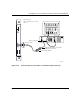
To connect to an alarm:
1.
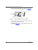
Using a 1/8 in. flat-tip screwdriver, loosen the screw on the terminal block
on the SSP interface Ethernet card or the SSP interface console card for
the connection that you are making (Figure 4-16)
.
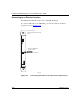
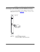
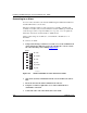
Figure 4-16. Alarm Terminal Block on the SSP Interface Cards
2.
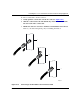
Strip 1/2 in. (10 mm) of insulation from the end of an AWG wire (#22 to
#16).
3.
Insert the wire into the alarm terminal block connector.
4.
Using the screwdriver, tighten the screw on the terminal block to
establish the connection.
5.
Connect the other end of the alarm cable to the alarm.
Min NO
Min COM
Min NC
Maj NO
Maj COM
Maj NC
Alarm
BAC0073A