NN10265-111 Multimedia Communication Portfolio Multimedia Communication Server RTP Media Portal Basics MCS 5100 3.5 Standard 4.
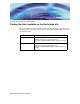
Copyright © Nortel Networks Limited 2006 Finding the latest updates on the Nortel web site The content of this documentation was current at the time the product was released. To check for updates to the latest documentation and software for MCS 5100, click one of the following links: Link to Takes you directly to the Latest Software Nortel page for MCS 5100 software located at www130.nortelnetworks.com/cgi-bin/eserv/cs/ main.jsp?cscat=SOFTWARE&resetFilter=1&tranProduct=124 82.
Copyright © Nortel Networks Limited 2006 NN10265-111 MCS 5100 3.5 Standard 4.
Copyright © Nortel Networks Limited 2006 How to get help This section explains how to get help for Nortel products and services. Getting help from the Nortel web site The best way to get technical support for Nortel products is from the Nortel Technical Support web site: www.nortel.com/support This site provides quick access to software, documentation, bulletins, and tools to address issues with Nortel products.
Copyright © Nortel Networks Limited 2006 6 Getting help from a specialist by using an Express Routing Code To access some Nortel Technical Solutions Centers, you can use an Express Routing Code (ERC) to quickly route your call to a specialist in your Nortel product or service. To locate the ERC for your product or service, go to: www.nortel.
Copyright © Nortel Networks Limited 2006 Overview How this chapter is organized This chapter is organized as follows: • Functional description on page 7 • Hardware on page 8 • Software on page 12 • Operations, administration, and management on page 12 • Interfaces on page 13 — Protocols on page 13 — Network interfaces on page 14 Functional description The Real-time Transport Protocol (RTP) Media Portal is an optional component that addresses media plane specific issues with advanced service deliv
Copyright © Nortel Networks Limited 2006 8 Figure 1, Network component topology, on page 8 is a graphical depiction of the RTP Media Portal’s position in a single-network MCS solution. Figure 1 Network component topology Hardware The RTP Media Portal resides on a Motorola* CPX8216T platform, a 16-slot CompactPCI (cPCI) chassis design.
Copyright © Nortel Networks Limited 2006 9 dividing the chassis shelf into two half-shelves consisting of 8-slots each. Note: The chassis logical Domains are not internet Domains. Rather, the term is used to identify Side A and Side B of the chassis. Other terms used interchangeably include: Domain A and Domain B, Left Domain and Right Domain, and half-shelf. An RTP Media Portal occupies a single logical operational Domain in the CPX8216T.
Copyright © Nortel Networks Limited 2006 10 to left (1-16). A front view of the CPX8216T is shown in Figure 3, Motorola chassis CPX8216T - front view, on page 10. Figure 3 Motorola chassis CPX8216T - front view A rear view of the CPX8216T is shown in Figure 4, Motorola chassis CPX8216T - back view, on page 11. NN10265-111 MCS 5100 3.5 Standard 4.
Copyright © Nortel Networks Limited 2006 11 Figure 4 Motorola chassis CPX8216T - back view Within the CPX8216T dual 8-slot architecture, each logical Domain in the chassis contains a dedicated host card (with an associated transition module in the rear), a slot dedicated to the Motorola Hot Swap Controller (HSC), and the remaining six slots which may be populated with Media Blades (media input/output cards with an associated transition module in the rear).
Copyright © Nortel Networks Limited 2006 12 Each logical Domain, and therefore each RTP Media Portal, consists of the following hardware components: • a single CPV5370 Intel processor board (the host card) with 1 GB memory, a SCSI input/output (I/O) daughter board, and rear Transition Module.
Copyright © Nortel Networks Limited 2006 13 components in the system and administrative access to OAM functions (including fault and configuration management). RTP Media Portal OAM data is stored on both the Management Module and the database. The Management Module stores alarm and log data. Configuration data is stored locally on the RTP Media Portal as well as persistently in the database. For a graphical view of these relationships, please refer to Figure 5, OAM interoperability, on page 13.
Copyright © Nortel Networks Limited 2006 • 14 TCP, Transmission Control Protocol, communicates configuration, performance data, logs, and alarms (OAM data) between the RTP Media Portal and the Management Module. Network interfaces The RTP Media Portal is comprised of two physical hardware subcomponents: a single Host CPU, and up to six (6) Media Blades. The following figure shows an example of RTP Media Portal dual-network connectivity between a Protected MCS Network and a Public Network.
Copyright © Nortel Networks Limited 2006 15 Figure 7 RTP Media Portal operational interface - single-network deployment Host CPU RTP Media Portal Control/OAM Network Media Blades Media Host CPU As shown in Figure 8, Control and OAM interface - CPV5370 Host card and RTP Media Portal, on page 16, the Rear Transition Module for the host card (CPV5370) provides the following: • COM2 port for connection to a terminal server and local monitor.
Copyright © Nortel Networks Limited 2006 16 Figure 8 Control and OAM interface - CPV5370 Host card and RTP Media Portal Rear Transition Module Front Main Board terminal server 100BaseT Ethernet (Standby) Control and OAM Protected MCS MCP Service Network Network 100BaseT Ethernet (Active) These Ethernet connections carry the following: • MPCP control messages to communicate with the SIP Application Module. • Operations, administration, and maintenance (OAM) data to the Management Module over TCP.
Copyright © Nortel Networks Limited 2006 17 illustrates media stream interfaces in a dual-network deployment between a Protected MCS Network and Public Network. Figure 9 Media stream interface – MCPN765 Media Blade to RTP Media Portal Protected MCS Network A Media Blade in the RTP Media Portal consists of the following input/output cards: • MCPN765 Front Main Board • TM-PIMC-0101 Rear Transition Module There is a 1:1 relationship between the Front Card and Rear Transition Module.
Copyright © Nortel Networks Limited 2006 18 The Rear Transition Module contains two, 10/100 BaseT Ethernet connections for RTP/RTCP/UDP media streams. Each Media Blade (pair of MCPN765 and TM-PIMC-0101 cards) performs the following functions: • Connectivity for RTP/RTCP/UDP media streams. • Address and Port Discovery (APD) for obscured media endpoints. • Relay of media packets between end points. • An array of NAT and/or NAPT functions.
Copyright © Nortel Networks Limited 2006 Maintenance updates How this chapter is organized This chapter is organized as follows: • Functional description on page 19 • Operations, administration, and management on page 19 • Maintenance update tasks on page 20 — Shut down the RTP Media Portal component on page 21 — Update the RTP Media Portal component on page 23 Functional description This chapter documents upgrade tasks to be performed when upgrading a maintenance release.
Copyright © Nortel Networks Limited 2006 20 active media sessions present. When this occurs, it is safe to proceed with the upgrade without affecting service. CAUTION It is possible to update and reboot one RTP Media Portal in a chassis, while the RTP Media Portal in the other half of the chassis continues to run the previous software. Once one RTP Media Portal is updated, the other RTP Media Portal in the chassis can be shutdown, locked, updated, and rebooted.
Copyright © Nortel Networks Limited 2006 21 followed when updating a software load for the RTP Media Portal component. From the System Management Console 1 Shut down the RTP Media Portal component. For details, please refer to Shut down the RTP Media Portal component on page 21. 2 Update the software load for the RTP Media Portal component. For details, please refer to Update the RTP Media Portal component on page 23.
Copyright © Nortel Networks Limited 2006 22 Figure 10 RTP Portal Shutdown 3 A confirmation window appears. Click on the Yes button to continue. Figure 11 RTP Portal Shutdown confirmation 4 The RTP Media Portal component shuts down gracefully and eventually goes into a LOCKED state when the last active media session ends (as seen in the General Information Area of the System Management Console). NN10265-111 MCS 5100 3.5 Standard 4.
Copyright © Nortel Networks Limited 2006 23 Update the RTP Media Portal component The following procedure describes how to update a load for the RTP Media Portal component. Note: Updates (both upgrades and downgrades) to network components must be performed in a specific order. Please refer to MCS 5100Basics (NN10270-100) for further information. From the System Management Console 1 In the System tree, right-click on the RTP Media Portal component. 2 From the pop-up menu, select the Update command.
Copyright © Nortel Networks Limited 2006 24 Figure 13 Update from the Configuration menu NN10265-111 MCS 5100 3.5 Standard 4.
Copyright © Nortel Networks Limited 2006 3 25 The Load List window appears. The window only shows software loads suitable for the RTP Media Portal component type, since this is the component type being updated. Figure 14 Load list for updating 4 Select the load version that should be used to update the RTP Media Portal. Click on the Apply button. 5 The System Management Console displays the RTP Media Portal configuration window. If required, modify any configuration properties.
Copyright © Nortel Networks Limited 2006 26 NN10265-111 MCS 5100 3.5 Standard 4.
Copyright © Nortel Networks Limited 2006 Full release upgrades How this chapter is organized This chapter is organized as follows: • Functional description on page 27 • Tools and utilities on page 27 • Operations, administration, and management on page 27 • Upgrade tasks on page 28 — Shutdown the target RTP Media Portal component on page 29 — Delete the previous load of the RTP Media Portal component on page 30 — Upgrade the RTP Media Portal component on page 30 — Deploy the RTP Media Portal compone
Copyright © Nortel Networks Limited 2006 28 active media sessions present. When this occurs, it is safe to proceed with the upgrade without affecting service. CAUTION It is possible to update and reboot one RTP Media Portal in a chassis, while the RTP Media Portal in the other half of the chassis continues to run the previous software. Once one RTP Media Portal is updated, the other RTP Media Portal in the chassis can be shutdown, locked, updated, and rebooted.
Copyright © Nortel Networks Limited 2006 29 3 Perform the upgrade. For details, refer to Upgrade the RTP Media Portal component on page 30. 4 Deploy the upgraded RTP Media Portal. For details, refer to Deploy the RTP Media Portal component on page 31. Shutdown the target RTP Media Portal component The following procedure describes how to shutdown the target RTP Media Portal component. From the System Management Console 1 In the System tree, right-click on the target RTP Media Portal component.
Copyright © Nortel Networks Limited 2006 30 Figure 16 RTP Portal Shutdown confirmation 4 The RTP Media Portal component shuts down gracefully and eventually goes into a LOCKED state when the last active media session ends (as seen in the General Information Area of the System Management Console). Delete the previous load of the RTP Media Portal component The following procedure describes how to delete the previous load of the RTP Media Portal component.
Copyright © Nortel Networks Limited 2006 31 cd 7 Dismount the CD. umount /mnt/cdrom 8 Eject the upgrade CD from the CD-ROM. eject 9 Remove the upgrade CD from the CD-ROM. 10 Repeat step 2 through step 9 for each upgrade CD. 11 Reboot the RTP Media Portal. reboot Deploy the RTP Media Portal component This section provides instruction to deploy the upgraded RTP Media Portal component.
Copyright © Nortel Networks Limited 2006 32 Figure 17 Add from the pop-up menu Note, you may also launch the add command from the pull-down Configuration menu. NN10265-111 MCS 5100 3.5 Standard 4.
Copyright © Nortel Networks Limited 2006 33 Figure 18 Add from the Configuration menu After Add > Component is selected, you must wait for the load list to retrieve. 3 The Load List window appears with all available component loads (except for those components already deployed to the server). Figure 19 Load list for adding 4 Select the desired software load version for the RTP Media Portal. Click on the Apply button.
Copyright © Nortel Networks Limited 2006 34 5 You will be prompted to configure the RTP Media Portal. For a description of these tabs and properties, please refer to Configuring and managing the RTP Media Portal component on page 43. 6 After entering the appropriate configuration information, enter a label (six characters or less) in the Service Component Name field. This label is the component name that appears in the System tree after deployment. Click on the Apply button.
Copyright © Nortel Networks Limited 2006 Fault management How this chapter is organized This chapter is organized as follows: • Network fault management on page 35 — Fault tolerance on page 35 — Fault management procedures on page 37 — RTP Media Portal alarms on page 38 — Informational and communication logs on page 39 — System logs on page 41 Network fault management The system handles network fault management through the reporting of alarms and logs to the Management Module.
Copyright © Nortel Networks Limited 2006 36 Application Module to immediately begin utilization of the RTP Media Portal for session requests whenever a failure condition occurs on the Active SIP Application Module. • Idle Session Detection — enables the RTP Media Portal to detect and recover media resources associated with idle media sessions. This basic capability enables the system to recover resources as well as maintain capacity and performance.
Copyright © Nortel Networks Limited 2006 37 service, if offers the remaining available capacity on the Media Blades for the processing of new sessions. Fault management procedures Alarm surveillance The following procedure lists steps to obtain information regarding alarms. From the System Management Console 1 In the System tree, select the appropriate RTP Media Portal component.
Copyright © Nortel Networks Limited 2006 38 Clearing an alarm The following procedure lists steps to clear an alarm. From the System Management Console 1 In the System tree, select the appropriate RTP Media Portal. component. 2 From the pull-down Tools menu, select Alarm Browser. 3 The Alarm Browser window appears displaying the alarms. 4 Double click the alarm row.
Copyright © Nortel Networks Limited 2006 39 Clearing the RTP103 Alarm (Best Blade Selection) 1 Verify that you can log in to the media blade from the host card. If successful, the MCP Service Network connection is OK. 2 Once you are logged in to the media blade, verify the media blade can reach the default gateway: ping the gateway IP address from the media blade. If successful, the network connection is OK. 3 Repeat for each media blade.
Copyright © Nortel Networks Limited 2006 40 communications. No action is required. An associated alarm is raised for each Media Blade which does not respond. • Blade Recovery-Mode Initiated, RTP909, indicates that the Host CPU was able to re-establish communication with a subtending Media Blade and that the Media Blade is supporting connections. No action is required.
Copyright © Nortel Networks Limited 2006 41 • Failed to Send Signal, RTP118, generated whenever an attempt to dispatch an outgoing signal fails. No action is required. • Failed to Reboot IO Exception, RTP919, generated whenever a request for reboot of the system fails due to a software request for said reboot. Report this log to your next level of support.
Copyright © Nortel Networks Limited 2006 42 NN10265-111 MCS 5100 3.5 Standard 4.
Copyright © Nortel Networks Limited 2006 Configuration management How this chapter is organized This chapter is organized as follows: • Tools and utilities on page 43 • Configuring and managing the RTP Media Portal component on page 43 — Deploying the RTP Media Portal server on page 44 — Adding the RTP Media Portal component on page 44 — Querying or modifying RTP Media Portal configuration properties on page 46 — Configuration tabs and properties on page 47 Tools and utilities Deployment and configurat
Copyright © Nortel Networks Limited 2006 44 Deploying the RTP Media Portal server For information regarding how to deploy and configure an RTP Media Portal server, please refer to MCS 5100 System Management Console User Guide (NN10273-111). Adding the RTP Media Portal component This procedure assumes that the server on which the RTP Media Portal will be deployed, has already been configured.
Copyright © Nortel Networks Limited 2006 45 Figure 22 Add from the Configuration menu After Add > Component is selected, you must wait for the load list to retrieve. 3 The Load List window appears with all available component loads (except for those components already deployed to the server). Figure 23 Load list for adding 4 Select the desired software load version for the RTP Media Portal. Click on the Apply button. 5 You will be prompted to configure the RTP Media Portal.
Copyright © Nortel Networks Limited 2006 7 46 When deployment completes, and information dialog message appears to indicate that the action was successful. Querying or modifying RTP Media Portal configuration properties Use the following procedure to query or modify the configuration properties for the RTP Media Portal component. From the System Management Console 1 In the System tree, find the appropriate RTP Media Portal component to be queried or modified.
Copyright © Nortel Networks Limited 2006 47 a Right-click the root level RTP Media Portal component and click Shutdown to shutdown and eventually lock the component so configuration properties can be modified. Note: After completing the shutdown, the RTP Media Portal component’s media resources are no longer available for new sessions and its state is automatically transitioned to LOCKED once all existing in-progress sessions are released.
Copyright © Nortel Networks Limited 2006 Figure 26 System Output Manager tab The following table details the configurable properties of the System Output Manager tab. Table 1 System Output Manager tab configurable properties Configuration Property Format Description Send to File Type: String Range: Null, 1-500 characters Default: SystemOutLog Name of file that additional detailed logs should be sent to.
Copyright © Nortel Networks Limited 2006 Figure 27 RTP Media Portal tab (1 of 3) MCS 5100 RTP Media Portal Basics 49
Copyright © Nortel Networks Limited 2006 50 Figure 28 RTP Media Portal tab (2 of 3) NN10265-111 MCS 5100 3.5 Standard 4.
Copyright © Nortel Networks Limited 2006 Figure 29 RTP Media Portal tab (3 of 3) The following table details the configurable properties of the RTP Media Portal tab. Table 2 RTP Media Portal tab configurable properties (Sheet 1 of 8) Configuration property Format Description Call Legs Type: String Range: 4096-MaxInt Default: 4096 Defines the bounds for internal data structures. This value is not normally changed. Default recommended.
Copyright © Nortel Networks Limited 2006 Table 2 RTP Media Portal tab configurable properties (Sheet 2 of 8) Configuration property Format Description RTP Portal IP Type: String Range: 7-15 characters Default: 0.0.0.0 MCP Service Network IP Address of the RTP Media Portal Host. Identifies a specific Host. AppSvr IP Type: String Range: 7-15 characters Default: 0.0.0.0 MCP Service Network IP Address of SIP Application Module to which this RTP Media Portal is assigned.
Copyright © Nortel Networks Limited 2006 Table 2 RTP Media Portal tab configurable properties (Sheet 3 of 8) Configuration property Format Description Polltimer Delay Type: String Range: 0-65535 Default: 20000 milliseconds Time span (in milliseconds) required for startup and initialization of the Media Blades. The Host waits this period of time before attempting to contact the Media Blades. Note: The use of the default value for this property is highly recommended.
Copyright © Nortel Networks Limited 2006 Table 2 RTP Media Portal tab configurable properties (Sheet 4 of 8) Configuration property Format Description Net1 Netmask Type: IP address Range: N/A Default: 255.255.255.0 (Used for the Media Blades, not for the host card.) The Net1 Netmask is the netmask used for routing on the network that is reachable by the NET1 interface on the media card. This is only used in dual-network configurations. Net2 Netmask Type: IP address Range: N/A Default: 255.255.
Copyright © Nortel Networks Limited 2006 Table 2 RTP Media Portal tab configurable properties (Sheet 5 of 8) Configuration property Format Description Idle Session Audit Period Type: String Range: 0-3600000 Default: 300000 (ms) The period of the audit that runs to detect idle media sessions on the media blade. Long Idle Duration Type: String Range: 0-65535 Default: 24 This represents the maximum amount of time that a RTP Media Portal resource may remain validly idle.
Copyright © Nortel Networks Limited 2006 Table 2 RTP Media Portal tab configurable properties (Sheet 6 of 8) Configuration property Format Description Activate IP Failover Type: Boolean Range: true/false Default: true Enables the RTP Media Portal Host to monitor the status of the MCP Service Network Interface and react accordingly. This basic capability enables the system to maintain service availability in the wake of MCP Service Network failures.
Copyright © Nortel Networks Limited 2006 Table 2 RTP Media Portal tab configurable properties (Sheet 7 of 8) Configuration property Format Description Net1 Media IP Type: IP Address Range: 7-15 characters Default: 0.0.0.0 The Net1 Media IP address of this particular media blade. Repeated for each media blade. Net2 Media IP Type: IP Address Range: 7-15 characters Default: 0.0.0.0 The Net2 Media IP address for this particular media blade. Repeated for each media blade.
Copyright © Nortel Networks Limited 2006 Table 2 RTP Media Portal tab configurable properties (Sheet 8 of 8) Configuration property Format Description InsertPortalWhenAnyBFW Type: Boolean Range: true/false Default: false If set to false, a RTP Media Portal is not used for calls when two Firewall clients are in the same Domain. If set to true, a RTP Media Portal is used when one or both clients in the same Domain are behind a Firewall.
Copyright © Nortel Networks Limited 2006 Accounting management Functional description The RTP Media Portal does not perform accounting management. However, an indication that an RTP Media Portal component was used during a session is provided in the accounting records. For more information on accounting, please refer to MCS 5100 Accounting Module Basics (NN10279-111).
Copyright © Nortel Networks Limited 2006 60 NN10265-111 MCS 5100 3.5 Standard 4.
Copyright © Nortel Networks Limited 2006 Performance management Functional description RTP Media Portal performance is monitored through the System Management Console by viewing Operational Measurements (OMs). For more information on RTP Media Portal OMs and the viewing of these OMs, please refer to MCS 5100 System Management Console User Guide (NN10273-111).
Copyright © Nortel Networks Limited 2006 62 NN10265-111 MCS 5100 3.5 Standard 4.
Copyright © Nortel Networks Limited 2006 Security and administration How this chapter is organized This chapter is organized as follows: • Security overview on page 63 — Network level security functions on page 63 — RTP Media Portal component level security functions on page 64 • User administration on page 65 Security overview One function of the RTP Media Portal is to secure the media interface to the MCP Services Network.
Copyright © Nortel Networks Limited 2006 64 Port randomization When the RTP Media Portal is deployed, each Media Blade is configured with a pool of ports containing a specific number of ports in a specific range based on configuration data (“Number Ports”, “Min Port Value”, “Max Port Value”, respectively). For more information on these configuration properties, refer to Table 2, RTP Media Portal tab configurable properties, on page 51.
Copyright © Nortel Networks Limited 2006 65 Packet filter/firewall As packets are received, the RTP Media Portal analyzes each packet to ensure the following: • The data format is RTP/RTCP/UDP, as indicated by the session description. All other packet types are discarded and logged as problems. • The source/destination addresses match the expected source/destination addresses indicated in the session description.
Copyright © Nortel Networks Limited 2006 66 NN10265-111 MCS 5100 3.5 Standard 4.
Copyright © Nortel Networks Limited 2006 Appendix A: Backup and recovery How this chapter is organized This chapter is organized as follows: • Backup and restore on page 67 — Prerequisites on page 67 — Duration on page 68 — Remote tape drive set up on page 69 — Backup to remote tape drive on page 70 — Restore on page 70 — Error scenarios on page 80 • Recovery on page 83 — Replacement of CPU host card on page 83 — Replacement of task processor on page 83 Backup and restore Prerequisites The following pr
Copyright © Nortel Networks Limited 2006 68 Auto Negotiate so that they too will respond in full duplex mode. Failure to set the mode to full duplex will result in restore times that are ten times normal. • For restore operation, server address information is required. • For restore operation, the Linux Recovery CD is required. The Linux Recovery CD is the Linuxcare Bootable Toolbox CD-ROM, available at: http://www.linuxcare.com/bootable_cd.
Copyright © Nortel Networks Limited 2006 69 operation. Use Unix commands to determine the size of the following partitions: • / • /boot • /var • /IMS • /usr Backup requires approximately 20 minutes per GB when using a USB tape drive, and approximately eight minutes per GB for a SCSI tape device. Restore requires approximately 35 minutes per GB, regardless of which type of tape drive is used.
Copyright © Nortel Networks Limited 2006 70 rsh -l sysadmin df -k where is the IP address of the remote host with the tape drive. 6 Output appears on screen, indicating the target system is correctly set for the restore operation. In not, contact your next line of support before continuing. Backup to remote tape drive The following procedure lists steps to backup the RTP Media Portal to tape. As the restore operation is manual, no logs are generated.
Copyright © Nortel Networks Limited 2006 71 before proceeding with the restore. For more information, refer to Remote tape drive set up on page 69. From the terminal server 1 Prepare the system for restore. For instructions, refer to Prepare system for restore on page 71. 2 Partition the hard drive. For instructions, refer to Partition the hard drive on page 74. 3 Initiate the rollback. For instructions, refer to Initiate restore on page 78.
Copyright © Nortel Networks Limited 2006 72 Figure 30 Enter BIOS Setup screen PhoenixPICOBIOS 4.0 Release 6.0 Copyright 1985-2000 Phoenix Technologies Ltd. All Rights Reserved CPV5370 BIOS 1.0RM01. Copyright 2001 Motorola, Inc. Build Time: 03/11/2001 17:58:18 CPU = Intel (R) Mobile Pentium (RO III processor 700 MHz 640K System RAM Passed Press to enter Setup 5 From the BIOS Setup Utility screen, use the arrow keys to move to the Boot menu.
Copyright © Nortel Networks Limited 2006 73 Figure 32 BIOS Setup: Boot Device Selection menu BIOS Setup Utility M ain M em ory Advanced Securit y BootD evicePriorit y 8XX SC SICD-RO M LSILogic !+H ardDrive !+Rem ovableD evice s !ATAPICD-RO M Drive !Legacy N etworkBoot Status Boot Exit Item Specific Help Keys used to view or confi gure device s: expandsor coll apses device s w it h a '+' or'-' expands all enables or disables a device . <+> and <->m oves the deviceup ordown.
Copyright © Nortel Networks Limited 2006 74 Partition the hard drive The following table lists fdisk commands used to partition the hard drive. Command Description m Display a list of available commands. n Create a new partition. p Print the current partition table. d Delete a partition. t Change the type of a partition. w Write the partition table and exit fdisk. The following procedure assumes a 40 GB hard drive, and includes partition recommendations.
Copyright © Nortel Networks Limited 2006 75 Figure 34 Red Hat: Edit hard disk Disk Setup To install Red Hat Linux, you must have at least one partition of 150 MB dedicated to Linux. We suggest placing that partition on one of the first two hard drives in your system so you can boot into Linux with LILO. /dev/sda - Seagate ST336938LW Done 3 Edit Back Type p and press Enter to display existing partitions. If any exist, type d to delete them.
Copyright © Nortel Networks Limited 2006 Figure 35 Red Hat: Create partition screen Command (m for help): p Disk /tmp/sda: 64 heads, 32 sectors, 35242 sylinders Units = sylinders of 2048 * 512 bytes Device Boot /tmp/sda1 /tmp/sda2 /tmp/sda3 /tmp/sda4 /tmp/sda5 /tmp/sda6 /tmp/sda7 Start 1 1002 6003 7004 7004 17005 27006 End Blocks 1001 1025008 6002 5121024 7003 1025024 35242 28916736 17004 10241008 27005 10241008 35242 8434672 Id 83 83 83 5 83 83 83 System Linux Linux Linux swap Extended Linux Linux
Copyright © Nortel Networks Limited 2006 77 then type 3 and press Enter. Press Enter to accept the default beginning block, and type +1000M and press Enter for the size. Command (m for help):n Command action e extended p primary partition (1-1) p Partition number (1-4): 3 First cylinder (6003-35242, default 1): Using default value 6003 Last cylinder or +size or +sizeM or +sizeK (6003-35242, default 35242): +1000M 7 Change the partition type for the third partition.
Copyright © Nortel Networks Limited 2006 10 78 To create the sixth partition type n and press Enter. Press Enter to accept the default beginning block, then type +10000M and press Enter for the size. Command (m for help):n First cylinder (17005-35242, default 17005): Using default value 17005 Last cylinder or +size or +sizeM or +sizeK (17005-35242, default 35242): +10000M 11 To create the seventh partition type n and press Enter.
Copyright © Nortel Networks Limited 2006 2 79 Locate the NIC driver. modprobe eepro100 3 Activate the network interface. ifconfig eth0 netmask up where is the IP address of the Portal Host card, and is the network address mask for this network segment. 4 Route the IP address of the MCP Service Network’s gateway. route add default gw where is the IP address of the network gateway for the subnet.
Copyright © Nortel Networks Limited 2006 80 mount /dev/sda6 /a cd /a restore rfv sysadmin@:/dev/rmt/0cn rm -f restoresymtable cd .. umount /dev/sda6 10 Restore the IMS partition. mount /dev/sda7 /a cd /a restore rfv sysadmin@:/dev/rmt/0cn rm -f restoresymtable cd ..
Copyright © Nortel Networks Limited 2006 81 Invalid IP address If an invalid IP address is entered, an information message is displayed. Example output: /usr/local/bin/mcp_backup.pl 47.47.47.46 no answer from 47.47.47.46 10:22:27 ERROR: System, 47.47.47.46, could not be pinged 10:22:27 Remote Backup verification failed, aborting backup process Logs are written to /export/home/sysadmin/bkup_restore/mcp_backup...
Copyright © Nortel Networks Limited 2006 82 DUMP: Lost connection to remote host. As the mcp_backup script “hangs”, type Ctrl-C to abort. (To kill the process from another session type => kill -9 .) Tape drive failure If something happens to the tape drive during a backup, an information message is displayed. Example output: DUMP: write: I/O error DUMP: write error 8320 blocks into volume 1 DUMP: Do you want to restart?: (“yes” or “no”) Answer no to this prompt.
Copyright © Nortel Networks Limited 2006 83 Mount volume 2 then enter volume name (default: /dev/rmt/0cn) Mount volume 3 then enter volume name (default: /dev/rmt/0cn) Read error while restoring ./me/loads/pool9/Files/B/UAS06.zip.bLfCbwYvd5YvveYt continue? [y n] n Verify volume and initialize maps Media read error: I/O error rest*: No such file or directory 12:49:35 Failed to Restore /IMS/imssipdb directory, aborting restore process Logs are written to /export/home/sysadmin/bkup_restore/mcp_recover.pl.
Copyright © Nortel Networks Limited 2006 84 2 Configure the MCPN765 Card. For more information, refer to Configuring the MCPN765 I/O Card on page 108. 3 Complete the installation. For more information, refer to Complete the installation on page 84. Complete the installation This section provides instruction for completing the installation of the MCPN765 Card. From the terminal device 1 Change directory. cd /etc 2 Edit the bladeEtherAddres file.
Copyright © Nortel Networks Limited 2006 Appendix B: RTP Media Portal installation How this chapter is organized This chapter is organized as follows: • Prerequisites on page 85 • Network deployment on page 87 • Installing RTP Media Portal on page 90 • Installing MCPN765 cards on page 104 Prerequisites This chapter provides instruction for installing a new RTP Media Portal.
Copyright © Nortel Networks Limited 2006 86 to allow I/O blades to boot and mount their file systems over the network. The complete base system can be installed in approximately 30 minutes. IMPORTANT: The installation procedures must be followed separately for each side if two Portals are installed in the same chassis.
Copyright © Nortel Networks Limited 2006 87 from blade NVRAM (use the niot ;h command to get the blade Ethernet addresses from the bug prompt). — RTP Portal chassis number — Gateway router address, may be different between host(s) and media card(s). — Netmasks for all assigned IP addresses — Root password for host(s) — Password for user “nortel” — Time zone Network deployment The RTP Media Portal may be configured as a dual- or single-network.
Copyright © Nortel Networks Limited 2006 Figure 36 RTP Media Portal single-network deployment Media Portal Baystack 470 U eth1 Host Blade eth0 U Media(Net2, eth1) Blade MCS VLAN (Net2, eth1) Media Blade The below table details the usage of the physical port for single-network deployment.
Copyright © Nortel Networks Limited 2006 two interfaces on the host are used in an active, standby mode and there is no interface redundancy on the media cards as each connects to a separate network. This configuration is depicted in Figure 37 on page 89.
Copyright © Nortel Networks Limited 2006 90 Installing RTP Media Portal This section outlines steps to install the RTP Media Portal. From the terminal console 1 Establish BIOS settings for the CPV5370 Host Card. For details, refer to BIOS configuration of the CPV5370 Host Card on page 90. 2 Install the base operating system, Red Hat 6.2. For details, refer to Installing the base Red Hat system on page 93 and Partitioning the hard drive on page 94 3 Complete the installation.
Copyright © Nortel Networks Limited 2006 91 Figure 38 BIOS Setup Utility screen BIOS Setup Utility Main Memory Advanced Security Status Boot Exit BIOS Version Board Version Board Serial No. CPV5501 1.0RM01 01-R5347P09A 9975639 __________________ CPU Type CPU Speed Pentium (R) III 700 MHz , , or selects field.
Copyright © Nortel Networks Limited 2006 9 92 Set the HA Config value to Enabled. Also, set the Domain that is being configured to Enable, and Disable for the other domain. CPU in slot 7 is Domain A, and CPU in slot 9 is Domain B. Example for Domain A, the Host Card in slot 7: HA Config [Enabled] Domain A [Enabled] Domain B [Disabled] 10 Press Esc twice to return to the Advanced menu. 11 Move to Remote Console and press Enter.
Copyright © Nortel Networks Limited 2006 20 93 While the system is rebooting, quickly change the console connection from COM1 to COM2. Use the escape sequence OQ to enter the BIOS set up screen again. If you do not see output on the terminal, make sure the terminal is set to 9600/8/n/1 and reset the CPV5370 card to try again. 21 When prompted, enter the supervisor password to ensure the password was correctly set and is using COM2 as the console port. 22 Insert the Red Hat 6.
Copyright © Nortel Networks Limited 2006 Figure 39 Red Hat: Installation Type screen Installation Type What type of system would you like to install? Install GNOME Workstation Install KDE Workstation Install Server System Install Custom System Upgrade Existing Installation OK 5 Back For Bad Partition Table, select Initialize. Partitioning the hard drive The following includes instruction to partition the hard drive. From the terminal server 1 Press w and press Enter to save changes and exit.
Copyright © Nortel Networks Limited 2006 Repeat for all partitions as necessary. Select OK when finished.
Copyright © Nortel Networks Limited 2006 Figure 41 Red Hat: Formatting partitions Choose Partitions to Format What partitions would you like to format? We strongly suggest formatting all of the system partitions, including /, /usr, and /ar. There is no need to format /home or /usr/local if they have already been configured during a previous install.
Copyright © Nortel Networks Limited 2006 97 Figure 42 Red Hat: LILO Configuration LILO Configuration A few systems will need to pass special options to the kernel at book time for the system to function properly. If you need to pass boot options to the kernel, enter them now. If you don't need any or aren't sure, leave this blank. [*] User linear mode (needed for some SCSI drives) sonsole=ttyS1,9600n8.................................................. OK Skip Back Select OK when finished.
Copyright © Nortel Networks Limited 2006 Figure 43 Red Hat: Network Configuration screen Network Configuration [ ] Use bootp/dhcp IP address: 47.47.47.48_________ Netmask: 250.250.250.0_______ Default gateway (IP): 48.48.48.49_________ Primary nameserver: __________________ OK 7 Back In the Device settings screen, accept the default setting and select OK to continue.
Copyright © Nortel Networks Limited 2006 Figure 45 Red Hat: Time Zone Selection screen Time Zone Selection What time zone are you located in? Current time: 13:12:56 CDT [ ] Hardware clock set to GMT? US/Aleutian US/Arizona US/Central US/East-Indiana US/Eastern OK 9 Back The next screen sets the root password. When prompted, enter the appropriate root password. Retype the password for confirmation and select OK to continue. Figure 46 Red Hat: Root Password screen Root Password Pick a root password.
Copyright © Nortel Networks Limited 2006 100 Figure 47 Red Hat: Add User screen Add User You should use a normal user account for most activities on your system. By not using the root account casually, you'll reduce the chance of disrupting your system's configuration.
Copyright © Nortel Networks Limited 2006 101 Figure 48 Red Hat: Authentication Configuration screen Authentication Configuration [ *] Use Shadow Passwords [ *] Enable MD5 Passwords [ ] Enable NIS NIS Domain: _________________________ NIS Server: [ ] Request server via broadcast or use: __________________________ OK 12 Back Select the software packages to install the following. • Networked Workstation • NFS Server • Anonymous FTP Server • Utilities De-select packages not included in this list.
Copyright © Nortel Networks Limited 2006 102 2 Insert the RTP Portal Install CD into the CD-ROM, and reboot the system by pressing the Reset button on the front of the Host CPU Card. 3 The system will reboot from the CD and begin executing the installation scripts. 4 Press Tab when the LILO prompt appears. Type install-serial at the prompt to begin the installation. 5 The system prompts for the following information. Host CPU slot number: [7 or 9] RTP Portal chassis number: [1, 2, 3,...
Copyright © Nortel Networks Limited 2006 103 12 Move to the Exit menu to save changes and exit the BIOS set up. The system will reboot. 13 After the system reboots, press the Enter key to boot the default image. 14 After booting, the login prompt will appear on screen. Configuring Network Time Protocol This section includes instruction for synchronizing the RTP Portal clock to the master clocks.
Copyright © Nortel Networks Limited 2006 104 Installing MCPN765 cards The following procedures outline instructions for adding MCPN765 I/O Cards in RTP Portal (Domain A). To add new I/O cards to Domain B, repeat these procedures. From a terminal device and the System Management Console 1 Set the MCPN765 I/O card. For more information, refer to Setting up the MCPN765 I/O Card on page 104. 2 Configure the MCPN765 card. For more information, refer to Configuring the MCPN765 I/O Card on page 108.
Copyright © Nortel Networks Limited 2006 105 PPC6-Bug>env Bug, AST or System environment [B/A/S] = B? Maximum Memory Usage (Mb, 0=AUTO) = 0? Field Service Menu Enable [Y/N] = N? Probe System for Supported I/O Controllers [Y/N] = Y? Auto-Initialize of NVRAM Header Enable [Y/N] = Y? Network PReP-Boot Mode Enable [Y/N] = Y? SCSI Bus Reset on Debugger Startup [Y/N] = N? Primary SCSI Bus Negotiations Type [A/S/N] = A? Primary SCSI Data Bus Width [W/N] = N? Secondary SCSI Identifier = "07"? NVRAM Boot List (GEV
Copyright © Nortel Networks Limited 2006 106 Memory Size Starting Address = 00000000? Memory Size Ending Address = 04000000? DRAM Speed in NANO Seconds = 8? ROM Bank A Access Speed (ns) = 90? ROM Bank B Access Speed (ns) = 120? DRAM Parity Enable [On-Detection/Always/Never O/A/N] = O? L2Cache Parity Enable [On-Detection/Always/Never O/A/N] = O? PCI Interrupts Route Control Registers (PIRQ0/1/2/3) = 0A0B0E0F? Serial Startup Code Master Enable [Y/N] = N? Serial Startup Code LF Enable [Y/N] = N? Firmware Com
Copyright © Nortel Networks Limited 2006 9 107 At the prompt, type reset to reboot the network once it completes the necessary self-tests. PPC6-Bug>reset Cold/Warm Reset [C,W] = C? Execute Local SCSI Bus Reset [Y,N] = N? Execute Local (CPU) Reset [Y,N] = N? y 10 Repeat this procedure for all I/O cards in the Domain. The Host Card IP address and the Broadcast IP address should be the same between all I/O Cards. 11 Unplug the console connection from the last I/O card. 12 Log in to the system as root.
Copyright © Nortel Networks Limited 2006 108 Configuring the MCPN765 I/O Card It is recommended the following procedure be completed during maintenance hours as it will require the RTP Media Portal to reboot, and be out of service for approximately 15-20 minutes. From the System Management Console 1 Expand the RTP Portal options, right-click on RTP Portal to select Shutdown. Figure 49 RTP Portal Shutdown 2 A confirmation window appears. Click on the Yes button to continue.
Copyright © Nortel Networks Limited 2006 109 If it is necessary to change the IP address, expand the RTP Portal options and right-click on RTP Portal to select Modify. From the RTP Media Portal tab to make the appropriate changes. Figure 51 RTP Media Portal tab No further action is required, and the final step in this procedure may be skipped. 4 Expand the RTP Portal options and right-click on RTP Portal to select Restart. The system will reboot.
Copyright © Nortel Networks Limited 2006 110 NN10265-111 MCS 5100 3.5 Standard 4.
Copyright © Nortel Networks Limited 2006 Appendix C: Basic call flows As described in Protocols on page 13, the RTP Media Portal component interfaces to the other network components using different protocols. These protocols are used to establish and manipulate media paths through the RTP Media Portal. This enables the SIP Application Module to control the media plane throughout the life of a session.
Copyright © Nortel Networks Limited 2006 112 The following sections provide some sample diagrams and descriptions of call flows to review the basic functionality of the RTP Media Portal component. Basic call without firewalls Figure 53, Basic call flow using the RTP Media Portal (unobscured endpoints), on page 112 shows the basic call flow for a client-to-client call using an RTP Media Portal without any firewall/NAPT traversal requirements.
Copyright © Nortel Networks Limited 2006 113 The following steps provide more detail about the call flow: 1. Client A initiates a SIP session to Client B by sending an Invite message to the SIP Application Module. Within the Invite message, Client A includes SDP information that identifies the called address (IP and port of B). 2. The SIP Application Module requests resources to support the half call (connection) between client B and the RTP Media Portal.
Copyright © Nortel Networks Limited 2006 Basic call with firewalls Figure 54, Basic call flow using the RTP Media Portal (with obscured endpoints), on page 114 shows the basic call flow for a client-to-client call using an RTP Media Portal with Address and Port Discovery (APD) functions enabled to facilitate firewall/NAPT traversal requirements.
Copyright © Nortel Networks Limited 2006 115 The following steps provide more detail about the call flow: 1. Client A initiates a SIP session to Client B by sending an Invite message to the SIP Application Module. Within the Invite message, Client A includes SDP information that identifies the called address (IP and port of B). The Invite passes through the firewall/NAT A. 2. The SIP Application Module requests resources to support the half call (connection) between Client B and the RTP Media Portal.
Copyright © Nortel Networks Limited 2006 116 10. Similarly, Client B sends its first media packet to address A’. The Portal discovers the media address used by Client B and completes the connection. Now that both endpoints are known, a complete media path exists through the Portal. The packet from Client B is forwarded to Client A. All subsequent packets sent by either endpoint are forwarded through the Portal to the other side of the call. 11.
Multimedia Communication Portfolio Multimedia Communication Server RTP Media Portal Basics Copyright © Nortel Networks Limited 2006 All Rights Reserved Information is subject to change without notice. Nortel Networks reserves the right to make changes in design or components as progress in engineering and manufacturing may warrant. *Nortel, Nortel (logo), and the Globemark are trademarks of Nortel Networks. *Motorola is a trademark of Motorola, Inc. *Solaris is a trademark of Sun Microsystems, Inc.