
Server User's Manual


240 2.0 Mb DTI implementation
Switch S3 - Mode of operation
This switch selects the operational mode for the NTAK10. The NTAK10
supports firmware that allows it to operate in the standard CEPT format
mode or the modified CEPT format used in France.
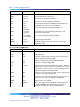
Table 86
Switch S3
Switch Off (Up) On (Down)
S3-1 Non-French Firmware French Firmware
S3-2 Spare Spare
Switch S4 - Carrier shield grounding
This switch supports selective shield grounding of the Tx and/or Rx pairs of
the carrier cable. Closing the switch (down position) applies Frame Ground
(FGND) to the coaxial carrier cable shield, creating a 75
3
/4 unbalanced
configuration. The Tx and Rx pairs are referenced with respect to the 2.0
Mb DTI card that is, Rx is carr ier received from the far-end device.
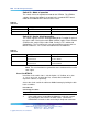
Table 87
Switch S4
Switch Off (Up) On (Down)
S4-1 Receive Shield
Unconnected
Frame Ground on
Receive Shield
S4-2 Transmit Shield
Unconnected
Frame Ground on
Transmit Shield
Note: The usual method is to ground the outer conductor of the receive
coax signal.
Insert the NTAK10
Install the circuit card in slots 1-9 in the Option 11C Cabinet, or in slots
11-19, 21-29, 31-39, 41-49 of the first, second, third, and fourth IP
expansion cabinets, respectively.
Secure the circuit card in the cabinet or Media Gateway by locking the lock
latch assemblies.
Procedure 39
Connecting the cables
Step Action
1
In the cabling area, located directly below the card cage, remove
the retaining bar that secures the MDF cables. Connect the
NTBK05DA/CA interface cable to the 50-pin Amphenol connector
Nortel Communication Server 1000
ISDN Primary Rate Interface Installation and Commissioning
NN43001-301 02.03 Standard
Release 5.5 7 December 2007
Copyright © 2003-2007, Nortel Networks
.