
Server User's Manual

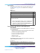

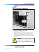


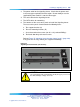
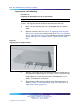
Table Of Contents
- New in this release
- How to get help
- Overview
- Contents
- What is Branch Office?
- Main Office and Branch Office Migration
- MG 1000B (MGC) compared to the MG 1000B (SSC)
- MGC Serial Ports
- Main office hardware description
- MG 1000B platform hardware description
- MG 1000B with MGC Data Networking
- MG 1000B platform configuration overview
- Capacity
- Software requirements
- Package Combinations
- Supported applications
- Survivability
- Bandwidth Management
- Contents
- Introduction
- Codec negotiation
- Configuring Bandwidth Management parameters
- Adaptive Network Bandwidth Management
- Tandem Bandwidth Management overview
- Dialing Plan Overview
- Network using Uniform Dialing Plan
- Common details
- Differences when every Branch Office HLOC is shared with the main office
- Call between two branch offices associated with the same main office
- Every Branch Office HLOC is shared with the main office
- No Branch Office HLOC is shared with the main office, but can be shared with another Branch Office
- No Branch Office HLOC is shared with the main office or another Branch Office
- Call between branch offices associated with different main office
- Every Branch Office HLOC is shared with the main office
- No Branch Office HLOC is shared with the main office or another Branch Office
- Summary of provisioning procedures for Tandem Bandwidth Management
- Provisioning Example of Tandem Bandwidth Management
- Network using mixed Coordinated Dialing Plan and Uniform Dialing Plan
- Call between two local branch offices
- Call between branch offices associated with different main offices
- Network using CDP only
- Bandwidth Management Support for Network Wide Virtual Office
- Alternative Call Routing for Network Bandwidth Management
- How the Branch Office feature works
- Planning and management
- Adding a Branch Office
- Converting a Small System to a Branch Office
- Upgrading to CS 1000 Release 5.0
- Main office configuration
- MG 1000B platform hardware installation
- MG 1000B software installation
- Branch Office configuration
- MG 1000B telephones
- Dialing plan configuration
- Emergency Services configuration
- Basic Emergency Services When VO Logged Out
- Abbreviated Dialing configuration
- Maintenance and diagnostics
- Preprogrammed data
- Branch Office engineering example
- On-net dialing plan configuration examples
- Off-net dialing plan configuration example
- List of terms
- Figures
- Figure 1 Branch Office associated with a CS 1000E main office
- Figure 2 CS 1000 Release 5.0 MG 1000B System
- Figure 3 MG 1000B Core/MG 1000B Expander
- Figure 4 CS 1000B and MG 1000B with MGC - Data Network Topology
- Figure 5 Single server port network connections (no dual-homing)
- Figure 6 Single server port network connections (dual-homing - non distributed)
- Figure 7 Single server port network connections (dual-homing - distributed)
- Figure 8 Multi server port network configuration (dual-homing - distributed)
- Figure 9 Single server port network connections - cascading
- Figure 10 Multi server (CP-P4) port network configuration (dual-homing - distributed)
- Figure 11 MG 1000B platform without MG 1000B Expander
- Figure 12 MG 1000B platform with MG 1000B Expander
- Figure 13 Configuring a codec
- Figure 14 Zones web page
- Figure 15 Maintenance Commands for Zones web page
- Figure 16 Element Manager - intrazone statistics
- Figure 17 Call Progress with Adaptive Network Bandwidth Management
- Figure 18 Adaptive Network Bandwidth Management graph
- Figure 19 Effect of the default CQos Coefficient
- Figure 20 Effect of a higher CQoS Coefficient
- Figure 21 Adaptive Network Bandwidth Management and CAC web page
- Figure 22 Element Manager - CAC parameters
- Figure 23 Sample output for PRT INTRAZONE command
- Figure 24 Sample output for PRT INTERZONE command
- Figure 25 A call between two branch offices tandems through the main office
- Figure 26 General legend
- Figure 27 Scenario 1: UDP throughout the network
- Figure 28 Call flow for Scenario 1 - local call
- Figure 29 Call flow for Scenario 1 - local call
- Figure 30 Call flow for Scenario 1- local call
- Figure 31 Call flow for Scenario 1 - call to a remote Branch Office (originator side)
- Figure 32 Call flow for Scenario 1 - call to remote Branch Office (destination side)
- Figure 33 Call flow for Scenario 1 - call to remote Branch Office (originator side)
- Figure 34 Call flow for Scenario 1 - call to remote Branch Office (destination side)
- Figure 35 Call flow for Scenario 1 - call to remote Branch Office (originator side)
- Figure 36 Call flow for Scenario 1 - call to remote Branch Office (destination side)
- Figure 37 Provisioning example
- Figure 38 Tandem endpoint configuration in Element Manager
- Figure 39 Scenario 2 - UDP between main offices, CDP inside the main office region
- Figure 40 Call flow for Scenario 2 - local call dials CDP
- Figure 41 Call flow for Scenario 2 - local call dial UDP
- Figure 42 Call flow for Scenario 2 - local call to remote Branch Office (originator side)
- Figure 43 Call flow for Scenario 2 - call to remote Branch Office (destination side)
- Figure 44 Scenario 3 - full CDP network
- Figure 45 Call flow for Scenario 3 - local call
- Figure 46 Call flow for Scenario 3 - calls to remote Branch Office (originator side)
- Figure 47 Call flow for Scenario 3- calls to remote Branch Office (destination side)
- Figure 48 Example of Alternative Call Routing for NBWM in operation
- Figure 49 Example of an alternately routed call between a Branch Office telephone in Normal Mode and a main office telephone
- Figure 50 Illustration showing digits dialed and outpulsed with Alternative Call Routing for NBWM
- Figure 51 Example of an alternately routed call between a main office telephone and a Branch Office telephone
- Figure 52 Illustration showing digits dialed and outpulsed with Alternative Call Routing for NBWM
- Figure 53 Example of an alternately routed call between a Branch Office telephone and another Branch Office telephone
- Figure 54 Illustration showing digits dialed and outpulsed with Alternative Call Routing for NBWM
- Figure 55 Access the Zone web page
- Figure 56 Access the Zones web page to select Alternate Routing for Calls between IP Stations
- Figure 57 Access the Alternate Routing for Calls between IP Stations web page to configure the feature
- Figure 58 System Maintenance web page
- Figure 59 Maintenance web page showing Select by Functionality
- Figure 60 The Maintenance Commands for Zones web page with PRT ZALT results
- Figure 61 Show the status of the Alternative Call Routing feature for the Branch Office zone
- Figure 62 Enable zone Branch Office behavior
- Figure 63 Alarm Suppression Time Period (ZAST)
- Figure 64 Configuration using S2 IP Address
- Figure 65 Network Music Service Feature Packaging Requirements
- Figure 66 Branch Office-specific zone configuration
- Figure 67 Branch Office-specific Zone Basic Property and Bandwidth Management
- Figure 68 Zone Time Difference and time zone
- Figure 69 Guide bracket installed in a rack
- Figure 70 Right ear bracket installed on the MG 1000B Core
- Figure 71 MG 1000B Core and MG 1000B Expander installed in a rack
- Figure 72 Power switch on the front of the MG 1000B Core
- Figure 73 Media Card
- Figure 74 Signaling Server
- Figure 75 Signaling Server brackets (two of each)
- Figure 76 Signaling Server support bracket
- Figure 77 Left hinge mount
- Figure 78 Right hinge mount
- Figure 79 Snapped-in bezel door
- Figure 80 Installed rack-mount bracket
- Figure 81 Rack-mounting the Signaling Server
- Figure 82 Back of Signaling Server
- Figure 83 Maintenance to Signaling Server connection
- Figure 84 Signaling Server with open bezel door
- Figure 85 MAC address
- Figure 86 Signaling Server indicators and power switch
- Figure 87 Tools menu
- Figure 88 Back of MG 1000B Core
- Figure 89 Confirm IP telephony node values H.323 Gatekeeper
- Figure 90 Confirm IP telephony node values SIP Redirect Server
- Figure 91 DSP Daughterboard
- Figure 92
- Figure 93 Branch Office-specific Zone Basic Property and Bandwidth Management
- Figure 94 Set-Based Installation Step 1
- Figure 95 Set-Based Installation Step 2
- Figure 96 Set-Based Installation Step 3
- Figure 97 Set-Based Installation Step 4
- Figure 98 Set-Based Installation Step 6
- Figure 99 Set-Based Installation Step 7
- Figure 100 Set-Based Installation complete
- Figure 101 Options menu
- Figure 102 Branch User ID
- Figure 103 Branch password
- Figure 104 Main Office Terminal Number
- Figure 105 Main office password
- Figure 106 Entry of Main Office TN
- Figure 107
- Figure 108 Options menu
- Figure 109 Virtual Office - logged in
- Figure 110 Virtual Office application menu
- Figure 111 Virtual or Branch soft key display
- Figure 112 Resume Normal Mode
- Figure 113 NRS Routing Entries window with no endpoint selected
- Figure 114 NRS Lookup path for gateway endpoints
- Figure 115 NRS Routing Entries window for selected endpoint
- Figure 116 NRS Add Routing Entry
- Figure 117 Zone Dialing Plan and Access Codes
- Figure 118 Zone Emergency Service Information
- Figure 119 New and changed prompts and responses in LD 16
- Figure 120 Required firmware version
- Figure 121 Branch Office traffic flow
- Figure 122 Coordinated Dialing Plan (CDP)
- Figure 123 Uniform Dialing Plan (UDP)
- Figure 124 Group Dialing Plan (GDP)
- Figure 125 Transferable DN (TNDN) (pre-transfer)
- Figure 126 Transferable DN (TNDN) (post-transfer)
- Figure 127 Off-net dialing plan example - call scenario.
- Figure 128 NRS Routing Entries window
- Figure 129 NRS Add Routing Entry
- Tables
- Table 1 Contents
- Table 2 CEMux Packs and daughter boards supported in MG 1000B with MGC
- Table 3 Card slots for MG 1000B Core and MG 1000B Expander
- Table 4 New IP Phone TN type naming convention
- Table 5 Best Bandwidth algorithm - codec type
- Table 6 Adaptive Network Bandwidth Management and CAC fields
- Table 7 Configuration details for the general case
- Table 8 Provisioning details for this case
- Table 9 Main office B DMI and RLI provisioning (for calls in Branch Office B)
- Table 10 Main office B LOC provisioning for LOC 741 841
- Table 11 Main office and Branch Office HLOC provisioning - Main office B and Branch Office B
- Table 12 Main office B LOC provisioning for LOC to remote main office system - main office A is LOC 842
- Table 13 Main office A LOC provisioning for LOC to remote main office systems - main office B is LOC 841
- Table 14 Branch Office terminating RLI provisioning
- Table 15 Provisioning details for this case
- Table 16 Provisioning details for this case
- Table 17 Sample values for Abbreviated Dialing
- Table 18 Example dialing string, area codes, and Access Codes
- Table 19 IP Phone node passwords
- Table 20 Readiness checklist
- Table 21 Tools checklist
- Table 22 DSP Daughterboard configurations
- Table 23 MGC Serial Port Capabilities
- Table 24 LD 11 Branch Office changes for Internet Telephones
- Table 25
- Table 26 Mapping between from CTYP parameter in SPN block to call-type before digit manipulation
- Table 27
- Table 28 Normal Operation troubleshooting
- Table 29 Legend for LD 32 STAT command Login status
- Table 30 Branch User Config troubleshooting
- Table 31 Passwords and codes
- Table 32 Default numbering plan First digit
- Table 33 Default numbering plan important extension numbers
- Table 34 Flexible Feature Codes
- Table 35 Pre-configured SDI ports
- Table 36 Pre-configured PTY ports
- Table 37 ESDI settings
- Table 38 Preprogrammed trunk route information
- Table 39 System parameters
- Table 40 Preprogrammed trunk route information
- Table 41 Equipment characteristics
- Table 42 Traffic characteristics
- Table 43 MG 1000B Core and MG 1000B Expander card type, number and devices
- Table 44 Full Duplex Ethernet bandwidth for one channel (one Erlang)
- Table 45 Traffic capacity at P.01, P.005, and P.001 GOS
- Table 46 LAN/WAN bandwidth for one channel (one Erlang)
- Procedures
- Procedure 1 Printing intrazone and interzone statistics for a zone
- Procedure 2 Displaying CAC parameters for one or more zones
- Procedure 3 Provisioning Tandem Bandwidth Management
- Procedure 4 Accessing the Zones web page
- Procedure 5 Printing zone ALTPrefix
- Procedure 6 Show Status
- Procedure 7 Enabling a zones Branch Office behavior
- Procedure 8 Suppress Alternative Call Routing for NBWM alarms
- Procedure 9 Configuring ESN and MG 1000B zones
- Procedure 10 Setting the IP Phone Installers Password
- Procedure 11 Setting and changing the Station Control Password Configuration
- Procedure 12 Configuring MG 1000B IP Phones at the main office using LD 11
- Procedure 13 Mounting the MG 1000B Core or MG 1000B Expander in a 19-inch rack
- Procedure 14 Preparing the Signaling Server for rack-mounting
- Procedure 15 Rack-mounting the Signaling Server
- Procedure 16 Connecting and powering up the Signaling Server
- Procedure 17 Creating a Signaling Server software CD-ROM
- Procedure 18 Viewing the Tools Menu
- Procedure 19 Changing the Signaling Server port speed
- Procedure 20 Verifying successful configuration
- Procedure 21 Configuring the ELAN network interface IP address
- Procedure 22 Connecting the Ethernet ports
- Procedure 23 Configuring the MG 1000B zone
- Procedure 24 Using Set-Based Installation
- Procedure 25 Configuring a Branch User
- Procedure 26 Testing the telephone for survivability
- Procedure 27 Installing IP Phones through overlays
- Procedure 28 Changing the SCPW
- Procedure 29 Using the Telephone Options feature
- Procedure 30 Using the Virtual Office Login feature
- Procedure 31 Using the Test Local Mode feature
- Procedure 32 Using the Set-Based Removal feature
- Procedure 33 Configuring the main office
- Procedure 34 Configuring the NRS database
- Procedure 35 Configuring the Branch Office
- Procedure 36 Testing PSTN access using an MG 1000B IP Phone
- Procedure 37 Configuring the main office
- Procedure 38 Configuring the Branch Office
- Procedure 39 Configuring the Branch Office zone
- Procedure 40 Testing ESDN using an MG 1000B Telephone
- Procedure 41 Configuring Speed Call List (SCL)
- Procedure 42 Configuring Pretranslation Groups
- Procedure 43 Assigning Pretranslation Groups to the telephones
- Procedure 44 Configuring Incoming DID Digit Conversion (IDC)
- Procedure 45 Upgrading firmware for CS 1000 Release 5.0
- Procedure 46 Upgrading firmware for CS 1000 Release 4.0 and earlier
- Procedure 47 Calculating traffic
- Procedure 48 Calculating Call Server Loading
- Procedure 49 Calculating TLAN subnet bandwidth for IP Phone traffic
- Procedure 50 Calculating MG 1000B with Virtual Trunk LAN/WAN
- Procedure 51 Calculating unspecified conference traffic
- Procedure 52 Calculating known conference traffic
- Procedure 53 Calculating Branch Office traffic, and LAN/WAN bandwidth without local messaging (CallPilot) capability

Installing an MG 1000B Core 223
Tools checklist
To install the system correctly, make sure that the tools listed in Table
21 "Tools checklist" (page 223) are available before assembling the
components.
Table 21
Tools checklist
Tools and components ü
screwdrivers
an ECOS 1023 POW-R-MATE or similar type of test meter
appropriate cable terminating tools
a drill for making lead holes
a computer for connecting directly to the MG 1000B Core by a DTE—DTE
null modem cable, with:
•
teletype terminal (ANSI-W emulation, serial port, 19 200 bps) for the
Call Server, MG 1000B Core, Signaling Server, and Media Cards
•
a web browser for Element Manager and NRS Management
(configure cache settings to check for new pages every time and to
empty the cache when the browser is closed)
Rack-mounting an MG 1000B Core or MG 1000B Expander
Items required
To install each MG 1000B Core or MG 1000B Expander in a 19-inch rack,
use the following items:
•
equipment layout plan (discussed in Communication Server 1000E:
Installation and Configuration (NN43041-310))
•
one pair of left and right guide brackets
•
one pair of left and right ear brackets
•
eight #12-24 screws
•
four #8-32 machine screws
The NTTK09 kit contains all of the above items with the exception of the
equipment layout plan and screws.
Procedure 13
Mounting the MG 1000B Core or MG 1000B Expander in a 19-inch rack
Step Action
References to "MG 1000B Core" in the following steps also apply to the
MG 1000B Expander.
Nortel Communication Server 1000
Branch Office Installation and Commissioning
NN43001-314 01.02 Standard
Release 5.0 20 June 2007
Copyright © 2007, Nortel Networks
.