Nortel Communication Server 1000 ISDN Basic Rate Interface Installation and Commissioning NN43001-318 .
Document status: Standard Document version: 01.02 Document date: 20 June 2007 Copyright © 2003-2007, Nortel Networks All Rights Reserved. Sourced in Canada The information in this document is subject to change without notice. The statements, configurations, technical data, and recommendations in this document are believed to be accurate and reliable, but are presented without express or implied warranty. Users must take full responsibility for their applications of any products specified in this document.
Revision history June 2007 Standard 01.02. This document is up-issued to remove the Nortel Networks Confidential statement. May 2007 Standard 01.01. This document is issued to support Communication Server 1000 Release 5.0. This document contains information previously contained in the following legacy document, now retired: ISDN Basic Rate Interface: Installation and Configuration (553-3001-218). No new content has been added for Communication Server 1000 Release 5.0.
Revision history Nortel Communication Server 1000 ISDN Basic Rate Interface Installation and Commissioning NN43001-318 01.02 Standard Release 5.0 20 June 2007 Copyright © 2003-2007, Nortel Networks .
Contents About this document 9 Subject 9 Applicable systems 10 Intended audience 11 Conventions 11 Related information 11 Preparing for installation Contents 13 Preparing the site 13 Unpacking and inspecting Taking inventory 14 13 14 Installing ISDN BRI hardware 15 Contents 15 Installing ISDN BRI hardware for line applications 15 Installing ISDN BRI hardware for trunk applications 38 Preparing the system 47 Contents 47 Introduction 47 Verifying ISDN BRI operation 47 Setting up ISDN BRI test te
Contents Testing an ISDN BRI trunk 103 Removing the test setup 103 Generating traffic reports 105 Contents 105 Introduction 105 Procedures Procedure Procedure Procedure Procedure Procedure Procedure Procedure Procedure Procedure 1 2 3 4 5 6 7 8 9 Procedure Procedure Procedure Procedure Procedure Procedure Procedure Procedure Procedure Procedure Procedure Procedure Procedure Procedure Procedure Procedure 10 11 12 13 14 15 16 17 18 19 20 21 22 23 24 25 Procedure Procedure Procedure Procedure Procedu
Contents 7 Procedure 39 Procedure 40 Procedure 41 Perform a D-channel Switched Virtual Circuit packet data transmission test using an MPH 101 Perform a B-channel Switched Virtual Circuit packet data transmission test using an MPH 102 Perform procedure to test an ISDN BRI trunk DSL 103 Nortel Communication Server 1000 ISDN Basic Rate Interface Installation and Commissioning NN43001-318 01.02 Standard Release 5.0 20 June 2007 Copyright © 2003-2007, Nortel Networks .
Contents Nortel Communication Server 1000 ISDN Basic Rate Interface Installation and Commissioning NN43001-318 01.02 Standard Release 5.0 20 June 2007 Copyright © 2003-2007, Nortel Networks .
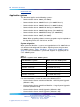
About this document This document is a global document. Contact your system supplier or your Nortel representative to verify that the hardware and software described are supported in your area. Note the following: • ISDN Basic Rate Interface (BRI) trunking is not available in North America. • The Basic Rate Signaling Concentrator (BRSC) is not supported on CS 1000M Cabinet. • The integrated Meridian 1 Packet Handler is not supported on CS 1000M Cabinet.
About this document www.nortel.
Related information 11 Intended audience This document is intended for individuals responsible for the planning, engineering, and administration of the applicable system.
About this document Online To access Nortel documentation online, click the Technical Documentation link under Support & Training on the Nortel home page: www.nortel.com CD-ROM To obtain Nortel documentation on CD-ROM, contact your Nortel customer representative. Nortel Communication Server 1000 ISDN Basic Rate Interface Installation and Commissioning NN43001-318 01.02 Standard Release 5.0 20 June 2007 Copyright © 2003-2007, Nortel Networks .
Preparing for installation Contents This section contains information on the following topics: "Preparing the site" (page 13) "Unpacking and inspecting" (page 14) "Taking inventory" (page 14) Preparing the site When installing a system, address the following factors. • environmental • structural • electrical For more information refer to Communication Server 1000M and Meridian 1 Large System Planning and Engineering (NN43021-220).
Preparing for installation 1 Large System Installation and Commissioning (NN43021-310) for a description of how to install the modules. Unpacking and inspecting ISDN BRI cards and external communication cables are shipped in separate packages. To unpack them, follow the general precautions recommended by computer and telephone equipment manufacturers. • Remove items that generate static charge from the installation site. • If the installation site is carpeted, spray it with an antistatic spray.
Installing ISDN BRI hardware Contents This section contains information on the following topics: "Installing ISDN BRI hardware for line applications" (page 15) "Installing ISDN BRI hardware for trunk applications" (page 38) "Selecting the card slots" (page 39) "Removing the module cover for card installation" (page 39) "Installing the MISP" (page 39) "Installing the clock reference on the SILC" (page 39) "Installing the SILC and the UILC" (page 42) "Connecting the system to the Main Distribution Frame (
Installing ISDN BRI hardware 4 Install the S/T Interface Linecards (SILCs) and/or U Interface Linecards (UILCs) or Basic Rate Signaling Concentrators (BRSCs). 5 Connect ISDN BRI terminals. This procedure comprises the following: • Connect the system to the Main Distribution Frame (MDF). • Cross-connect the MDF. • Connect ISDN BRI terminals to the DSL. • Initialize the ISDN BRI terminals.
Installing ISDN BRI hardware for line applications 17 2 Locate the card slots in the modules that house ISDN BRI cards. Group all SILCs, UILCs, BRSCs, superloops and the MISP that supports them in the same network group to avoid using junctors for dedicated connections. —End— The following rules apply when selecting the card slots: MISPs • MISPs are inserted into the Core/Network Module for Large Systems (Multi Group).
Installing ISDN BRI hardware • Group all SILCs, UILCs, BRSCs and the MISP that supports them in the same network group to avoid using junctors for dedicated connections. Figures 1 through 3, beginning Figure 1 "NT8D35 Network module (Large System)" (page 18) show typical module configurations. Figure 1 "NT8D35 Network module (Large System)" (page 18) shows the NT8D35 Network module.
Installing ISDN BRI hardware for line applications 19 Figure 2 NT8D37 IPE module (Large System) Figure 3 "NT4N41 Core/Network module (Large System)" (page 19) shows the NT4N41 Core/Network module. Figure 3 NT4N41 Core/Network module (Large System) Nortel Communication Server 1000 ISDN Basic Rate Interface Installation and Commissioning NN43001-318 01.02 Standard Release 5.0 20 June 2007 Copyright © 2003-2007, Nortel Networks .
Installing ISDN BRI hardware Procedure 2 Remove the module cover for card installation Step Action To remove the covers from the modules with unused card slots, follow the procedure below. Refer to Figure 4 "Module cover locking latches" (page 20). 1 Use a flat-blade screwdriver to unlock the left latch on the front of the cover by turning the screw 1/4 turn clockwise. 2 Use a flat-blade screwdriver to unlock the right latch on the front of the cover by turning the screw 1/4 turn counterclockwise.
Installing ISDN BRI hardware for line applications 21 Procedure 3 Installing the MISP Step Action Once covers have been removed and card slot locations selected for ISDN BRI cards, install the MISP cards. 1 Hold the MISP by its card-locking devices. Squeeze the tabs to unlatch the card-locking devices and lift the tabs out and away from the card. 2 Insert the MISP into the selected card slot of the module so it engages the card guides in the module.
Installing ISDN BRI hardware 1 Hold the MISP by its card-locking devices. Squeeze the tabs to unlatch the card-locking devices and lift the tabs out and away from the card. 2 Carefully remove the MISP from its card slot, and slowly slide the card from the module. —End— Procedure 5 Installing the BRSC, SILC, and UILC Step Action After MISPs are installed, install SILCs, UILCs, and BRSCs, as required.
Installing ISDN BRI hardware for line applications 23 8 Repeat steps 1 through 7 for each card requiring installation. —End— Procedure 6 Remove the BRSC, SILC, and UILC Step Action Perform the following steps to remove the BRSC, SILC, and the UILC. 1 Hold the card by its card-locking devices. Squeeze the tabs to unlatch the card-locking devices and lift them away from the card. 2 Carefully disengage the BRSC, SILC, or UILC from the backplane connector, and slowly slide the card from the module.
Installing ISDN BRI hardware Figure 5 Connect the ISDN BRI terminals to the Large System Procedure 8 Connect the modules to the MDF Step Action Modules connect to the MDF using NE-A25B cables with 50-pin D-type male connectors on each end. One end of the cable plugs into the Input/Output (I/O) panel at the rear of the module, and the other end plugs into the MDF. Nortel Communication Server 1000 ISDN Basic Rate Interface Installation and Commissioning NN43001-318 01.02 Standard Release 5.
Installing ISDN BRI hardware for line applications 25 Figure 6 "Connect the system to the MDF" (page 26) shows the cable connection between the system and the MDF. 1 Determine the number of NE-A25B cables needed to connect one module to the MDF. 2 Label each end of the cable specifying the module number, the connector name (A, B, C), and the card type (SILC or UILC). 3 Plug one end of a cable into the appropriate connector on the I/O panel at the rear of the module.
Installing ISDN BRI hardware Figure 6 Connect the system to the MDF SILC/UILC port designations at the MDF Table 3 "SILC port designations at the MDF: NT8D37 IPE module (16-cable configuration)" (page 27) and Table 4 "UILC port designation labels at the MDF: NT8D37 IPE module (16-cable configuration)" (page 27) provide SILC/UILC port designations at the MDF for the NT8D37 IPE.
Installing ISDN BRI hardware for line applications 27 UILC port designation labels for the IPE and CE modules are shown in Table 4 "UILC port designation labels at the MDF: NT8D37 IPE module (16-cable configuration)" (page 27).
Installing ISDN BRI hardware Cross-connecting the MDF The MDF cross-connects NE-A25B cables connected to SILC and UILC ports with building wiring connected to ISDN BRI terminals. Nortel Communication Server 1000 ISDN Basic Rate Interface Installation and Commissioning NN43001-318 01.02 Standard Release 5.0 20 June 2007 Copyright © 2003-2007, Nortel Networks .
Installing ISDN BRI hardware for line applications 29 Each SILC provides eight four-wire full-duplex ports. These ports are connected to building wiring to form DSLs. These ports are polarity-sensitive. Signal polarity must be maintained along each loop. Each UILC provides eight two-wire full-duplex ports. These ports are connected to twisted pair building wiring to form DSLs. These DSLs are not polarity-sensitive and, although recommended, it is not necessary to maintain signal polarity along each loop.
Installing ISDN BRI hardware Interface Feature Fundamentals (NN43001-580) for engineering rules and locations of terminating resistors. —End— Figure 7 "Cross-connect the SILC port to the office wiring" (page 31) and Figure 8 "Cross-connect the UILC port to the office wiring" (page 32) illustrate a cross-connection of an SILC port and an UILC port to the building wiring. Nortel Communication Server 1000 ISDN Basic Rate Interface Installation and Commissioning NN43001-318 01.02 Standard Release 5.
Installing ISDN BRI hardware for line applications 31 Figure 7 Cross-connect the SILC port to the office wiring Nortel Communication Server 1000 ISDN Basic Rate Interface Installation and Commissioning NN43001-318 01.02 Standard Release 5.0 20 June 2007 Copyright © 2003-2007, Nortel Networks .
Installing ISDN BRI hardware Figure 8 Cross-connect the UILC port to the office wiring Nortel Communication Server 1000 ISDN Basic Rate Interface Installation and Commissioning NN43001-318 01.02 Standard Release 5.0 20 June 2007 Copyright © 2003-2007, Nortel Networks .
Installing ISDN BRI hardware for line applications 33 Table 5 "NT8D37 IPE moduleSILC and UILC pair-terminations for connectors A, E, K, R (12-cable configuration)" (page 33) shows pair-terminations for connectors.
Installing ISDN BRI hardware Port signals I/O panel connectors Pair color B F L UILC Pairs 2Tx - / 2Tx + 2Rx + / 2Rx - 2T / 2R 30 / 5 31 / 6 W-S / S-W R-BL / BL-R 2 3Tx - / 3Tx + 3Rx + / 3Rx - 3T / 3R 32 / 7 33 / 8 R-O / O-R R-G / G-R 3 4Tx - / 4Tx + 4Rx + / 4Rx - 4T / 4R 34 / 9 35 / 10 R-BR / BR-R R-S / S-R 4 5Tx - / 5Tx + 5Rx + / 5Rx - 5T / 5R 36 / 11 37 / 12 BK-BL / BL-BK BK-O / O-BK 5 6Tx - / 6Tx + 6Rx + / 6Rx - 6T / 6R 38 / 13 39 / 14 BK-G / G-BK BK-BR / BK-BR 6 7Tx
Installing ISDN BRI hardware for line applications 35 Port signals I/O panel connectors Pair color C G M T Card port SILC UILC Pairs 7Tx - / 7Tx + 7Rx + / 7Rx - 7T / 7R 32 / 7 33 / 8 R-O / O-R R-G / G-R 0Tx - / 0Tx + 0Rx + / 0Rx - 0T / 0R 34 / 9 35 / 10 R-BR / BR-R R-S / S-R 1Tx - / 1Tx + 1Rx + / 1Rx - 1T / 1R 36 / 11 37 / 12 BK-BL / BL-BK BK-O / O-BK 1 2Tx - / 2Tx + 2Rx + / 2Rx - 2T / 2R 38 / 13 39 / 14 BK-G / G-BK BK-BR / BK-BR 2 3Tx - / 3Tx + 3Rx + / 3Rx - 3T / 3R 40 / 15 4
Installing ISDN BRI hardware Procedure 10 Connecting the ISDN BRI terminals to the DSL Step Action 1 Plug one end of the modular cable into the ISDN BRI interface connector on the terminal and the other end of the modular cable into the wall outlet. 2 For an SILC S/T interface terminal with an optional auxiliary power source, plug the power source into the wall outlet, then plug the cable into the power source’s RJ-45 jack.
Installing ISDN BRI hardware for line applications 37 Figure 9 Connect the ISDN BRI terminal to the S/T interface Nortel Communication Server 1000 ISDN Basic Rate Interface Installation and Commissioning NN43001-318 01.02 Standard Release 5.0 20 June 2007 Copyright © 2003-2007, Nortel Networks .
Installing ISDN BRI hardware Figure 10 Connect the ISDN BRI network termination (NT1) to the U interface Installing ISDN BRI hardware for trunk applications This section explains how to install ISDN BRI hardware to support ISDN BRI trunk applications. The system must already be installed and operating according to the instructions in Communication Server 1000M and Meridian 1 Large System Installation and Commissioning (NN43021-310) before performing these procedures.
Installing ISDN BRI hardware for trunk applications 39 2. Install the MISP. 3. Install clock referencing on the SILC. 4. Install the SILC and/or UILC. 5. Connect the system to the MDF. 6. Cross-connect the MDF (in Terminal Equipment mode).
Installing ISDN BRI hardware exchange the Tx and Rx pair position. This rewiring is done at the Main Distribution Frame (MDF). 2 Remove the phantom power jumpers (two jumpers per DSL) from the pin headers. 3 Place the SILC in the selected IPE slot. 4 Configure the selected DSL as Terminal Equipment (TE) mode in LD 27. 5 Enable the clock in LD 60 to output the clock references to the IPE back plane pins. 6 Configure the Clock Controller card to accept ISDN BRI clock reference.
Installing ISDN BRI hardware for trunk applications 41 Procedure 12 Connecting clock reference cables Step Action 1 Search for available D-sub 9 connector slots on the I/O panels of the selected IPE and CE I/O modules (if the I/O panel is equipped with D-sub 9 connector slots). If none is available, look for an empty slot used for 25-pair wire connectors (the cables contain two adapter plates to convert a 25-wire slot to two D-sub 9 connector slots).
Installing ISDN BRI hardware The SILC can recover the network clock from the received data stream using on-chip phase lock loops. The clock frequency that is recovered is 2.56 MHz. The jitter and wander conform to CCITT recommendations. All of the S/T chips on the SILC could be configured as Terminal Equipment Slaves (TES), but only the clocks recovered from DSL0 and DSL1 are routed to the back plane connector pins. These clocks are provided as differential pairs on back plane pins.
Installing ISDN BRI hardware for trunk applications 43 Figure 12 Connect the network termination to the U interface and to the S/T interface (in TE mode) Nortel Communication Server 1000 ISDN Basic Rate Interface Installation and Commissioning NN43001-318 01.02 Standard Release 5.0 20 June 2007 Copyright © 2003-2007, Nortel Networks .
Installing ISDN BRI hardware Card location forms Use the following card location forms when installing SILC/UILC and BRSC cards.
Installing ISDN BRI hardware for trunk applications 45 Card Type (SILC/UILC or BRSC) IPE Module number IPE module slot number I/O panel connector SILC/UILC or BRSC ports 7 G 0–7 8 K 0–7 9 L 0–7 10 L M 0–3 4–7 11 M 0–7 12 R 0–7 13 S 0–7 14 S T 0–3 4–7 Nortel Communication Server 1000 ISDN Basic Rate Interface Installation and Commissioning NN43001-318 01.02 Standard Release 5.0 20 June 2007 Copyright © 2003-2007, Nortel Networks .
Installing ISDN BRI hardware Nortel Communication Server 1000 ISDN Basic Rate Interface Installation and Commissioning NN43001-318 01.02 Standard Release 5.0 20 June 2007 Copyright © 2003-2007, Nortel Networks .
Preparing the system Contents This section contains information on the following topics: "Introduction" (page 47) "Verifying ISDN BRI operation" (page 47) "Setting up ISDN BRI test terminals and trunks" (page 48) Introduction This chapter describes how to prepare ISDN BRI equipment for acceptance testing. It explains how to verify that ISDN BRI cards are enabled and functioning correctly and how to correct any problems before starting the test.
Preparing the system correct a problem, refer to ISDN Basic Rate Interface Maintenance (NN43001-718). If all indicator LEDs on ISDN BRI equipment are extinguished (with the exception of the CC LED on an MISP), the equipment is functional and you can set up the terminals for this test. Setting up ISDN BRI test terminals and trunks Set up ISDN BRI terminals To conduct acceptance testing for ISDN BRI terminals, you must have a setup that can verify basic ISDN BRI functions and features.
Setting up ISDN BRI test terminals and trunks 49 —End— After you have completed the setup to perform acceptance testing, proceed with the tests described in "Testing ISDN BRI functions" (page 87). Figure 13 ISDN BRI acceptance testing setup for terminals Set up ISDN BRI trunking - Local Exchange connectivity Figure 14 "ISDN BRI acceptance testing setup for trunking – Local Exchange connectivity" (page 50) illustrates a typical configuration to test ISDN BRI Local Exchange connectivity.
Preparing the system is connected to a Network Termination (NT1) device, which is physically located on the same premises as the system. The NT1 device connects to the Local Exchange that supports Numeris VN2, 1TR6 or D70 protocol through a U interface. The distance limitation of the NT1 from the Local Exchange depends on the distance supported by the Local Exchange. To achieve system clock synchronization, configure the system as a slave to the local exchange.
Setting up ISDN BRI test terminals and trunks 51 the system slave to the local exchange; the clock source may be derived either from the ISDN BRI local exchange connections or from other ISDN BRI/PRI/DTI local exchange connections, if available. Figure 15 ISDN BRI acceptance testing setup for trunking - TIE trunk connectivity Nortel Communication Server 1000 ISDN Basic Rate Interface Installation and Commissioning NN43001-318 01.02 Standard Release 5.0 20 June 2007 Copyright © 2003-2007, Nortel Networks .
Preparing the system Nortel Communication Server 1000 ISDN Basic Rate Interface Installation and Commissioning NN43001-318 01.02 Standard Release 5.0 20 June 2007 Copyright © 2003-2007, Nortel Networks .
Configuring ISDN BRI hardware Contents This section contains information on the following topics: "Hardware requirements" (page 53) "Line and packet data applications" (page 53) "ISDN BRI trunking" (page 54) "Configuring ISDN BRI trunking with IP expansion cabinets or MG 1000S systems" (page 55) "Summary" (page 56) "Installation procedures" (page 58) Hardware requirements This section contains the hardware requirements for: • line and packet data applications • ISDN BRI trunking Line and packet dat
Configuring ISDN BRI hardware Hardware Product code Description Terminating resistor A0378866 Terminating resistor PRI circuit card (one only) Required for packet data implementation only. Packet handler NTRB21 1.5Mb TMDI circuit card with built-in downloadable D-channel NTAK09 1.5 Mb DTI/PRI circuit card NTAK79 2.0 Mb PRI circuit card NTBK50 2.0 Mb PRI circuit card used with the downloadable D-channel application Required for packet data implementation only.
Configuring ISDN BRI trunking with IP expansion cabinets or MG 1000S systems 55 Table 13 "Hardware requirements for ISDN BRI trunking" (page 55) lists the hardware required to configure ISDN BRI trunking. Table 13 Hardware requirements for ISDN BRI trunking Hardware Product code Description MISP circuit card NTBK22 The MISP card (NTBK22) is specific to Small Systems and CS 1000S systems. It performs Data Link (Layer 2) and Network (Layer 3) processing associated with the OSI protocol.
Configuring ISDN BRI hardware Configure DSL for ISDN BRI trunking in LD 27. Refer to Table 14 "Correct responses to LOOP and MISP prompts in LD 27" (page 56) for the correct response to the MISP prompt.
Installation procedures 57 secondary reference clock. These reference clock sources are derived from either BRI spans or DSLs (DSL 0 and/or DSL 1). Note 2: A clock controller is required in every cabinet or MG 1000S that contains a digital trunk. 5 Install the SILCs and UILCs. See Procedure 17 "Installing the SILCs and UILCs" (page 61). 6 Remove the SILCS and UILCs, if previously installed. See Procedure 18 "Removing the SILC and UILC" (page 64). 7 Install the PRI hardware.
Configuring ISDN BRI hardware —End— Installation procedures Procedure 14 Selecting the card slots Step Action 1 Select the appropriate ISDN BRI circuit card slot assignments in the Small System by using Table 15 "Small System shelf slot assignments for ISDN BRI cards" (page 58).
Installation procedures 59 ISDN BRI Card CS 100 0S, CS 1000M, OPtion 11C Chassis MISP (see Note 2) SILC is not clock reference SILC is cloc k reference UILC 1-4 1-4 1-4 1-4 MG 1000S 1 11-14 11-14 11-14 11-14 MG 1000S 2 21-24 21-24 21-24 21-24 MG 1000S 3 31-34 31-34 31-34 31-34 MG 1000S 4 41-44 41-44 41-44 41-44 Expansion 1 Not applicable 17-20 17-20 17-20 27-30 27-30 27-30 Expansion 3 37-40 37-40 37-40 Expansion 4 47-50 47-50 47-50 Call Server Expansion 2 Not
Configuring ISDN BRI hardware • The LED lights, flashes three times and then turns off – indicates the MISP is operating correctly and is configured and enabled. • Any other LED behavior indicates a defective MISP circuit card. Note: The Flash ROM can become corrupted if loss of power occurs during programming of the Flash ROM. If this occurs, the Flash ROM automatically re-initializes when the MISP is installed and powered up.
Installation procedures 61 • If the primary reference clock is derived from a BRI DSL, then the CC daughterboard is on the MISP associated with that line card. DSL0 of that line card is used to generate the reference clock. • To use a DTI/PRI as a secondary clock source reference, the clock controller daughterboard must reside on a DTI, PRI, or MISP. The clock is extracted from the target DTI/PRI span and routed to the clock controller over the back plane.
Configuring ISDN BRI hardware Figure 16 SILC line power options Store unused jumper plugs on position J1 of the SILC for future use. The following are descriptions of the three options and their jumper settings. • Normal power on the TX and RX leads. This option is set at the factory and provides normal power (-48V or -40V) on the TX lead and battery return (BRTN) on the RX lead to power the terminal.
Installation procedures 63 Figure 17 Jumper plug settings for normal power on the TX and RX leads • Reverse power on the TX and RX leads. This option is used only in Japan and provides power (-48V or -40V) on the RX lead and battery return (BRTN) on the TX lead to power the terminal. To implement it, install one jumper plug across the RX and PWR pins, and one across the BRTN and TX pins as shown in Figure 18 "Jumper plug settings for reverse power on the TX and RX leads" (page 63).
Configuring ISDN BRI hardware 6 7 Observe the behaviors of the LED on the faceplate of the MISP to determine its status: • The LED lights, flashes three times, and then remains lit – indicates the card is operating correctly, but is not configured. • The LED lights, flashes three times, and then turns off – indicates the card is operating correctly and is configured. • Any other LED behavior suggests a defective circuit card.
Installation procedures 65 Connecting the ISDN BRI terminals (for line applications) For line applications, five procedures are required to connect ISDN BRI terminals to the system: Step Action 1 Connect system cables to the cross-connect terminal. See Procedure 20 "Connecting system cables to the cross-connect terminal" (page 66). 2 Cross-connect the DSLs at the cross-connect terminal. See Procedure 21 "Cross-connecting the DSLs at the cross-connect terminal" (page 70).
Configuring ISDN BRI hardware Figure 19 Connecting ISDN BRI terminals to the system Procedure 20 Connecting system cables to the cross-connect terminal Step Action Each card slot equipped with a SILC or UILC requires one NE-A25B 25-pair connector cable. 1 Remove the connector retaining bar from the connector panel in the lower part of each cabinet. See Figure 20 "Cable connectors in Nortel Communication Server 1000 ISDN Basic Rate Interface Installation and Commissioning NN43001-318 01.
Installation procedures 67 main cabinet" (page 68) and Figure 21 "Cable connectors in the expansion cabinet" (page 68) on Figure 20 "Cable connectors in main cabinet" (page 68), and Figure 22 "Cable connectors in the second expansion cabinet" (page 69). 2 Connect an NE-A25B cable to each connector associated with a card slot containing a SILC or UILC circuit card.
Configuring ISDN BRI hardware Figure 20 Cable connectors in main cabinet Figure 21 Cable connectors in the expansion cabinet Nortel Communication Server 1000 ISDN Basic Rate Interface Installation and Commissioning NN43001-318 01.02 Standard Release 5.0 20 June 2007 Copyright © 2003-2007, Nortel Networks .
Installation procedures 69 Figure 22 Cable connectors in the second expansion cabinet Figure 23 Back of MG 1000S cable connectors Figure 24 SILC port designation label at the cross-connect terminal Note: The pair designated TX- TX+ is the transmit pair. The pair designated RX- RX+ is the receive pair. A SILC port supplies 2 W of Nortel Communication Server 1000 ISDN Basic Rate Interface Installation and Commissioning NN43001-318 01.02 Standard Release 5.
Configuring ISDN BRI hardware power at -48 V (-40 V for Europe), simplexed over the transmit and receive pairs. The transmit pair is negative with respect to the receive pair. Figure 25 UILC port designation label at the cross-connect terminal Note: The cable pair designated T R is a 2B1Q full-duplex U interface. Cross-connecting the DSLs Each SILC provides eight four-wire, full-duplex ports. These ports connect to building wiring facilities to form DSLs.
Installation procedures 71 Table 16 "SILC and UILC port assignments connectors at cross-connect terminal" (page 71) identifies SILC and UILC port assignments connectors at the cross-connect terminal.
Configuring ISDN BRI hardware SILC port signals UILC port signals Connector pin number and wire color code 6 TX- 6T 38 BK-G 6 TX+ 6R 13 G-BK 6 RX- 39 BK-BR 6 RX+ 14 BR-BK Wire color codes 7 TX- 7T 40 BK-S 7 TX+ 7R 15 S-BK 7 RX- 41 Y-BL 7 RX+ 16 BL-Y Card ports Port 6 Port 7 Note: The cable pair designated TX- TX+ is the transmit pair and the pair designated RX+ RX- is the receive pair of the S/T interface.
Installation procedures 73 Figure 26 Cross-connecting a SILC port to the office wiring Nortel Communication Server 1000 ISDN Basic Rate Interface Installation and Commissioning NN43001-318 01.02 Standard Release 5.0 20 June 2007 Copyright © 2003-2007, Nortel Networks .
Configuring ISDN BRI hardware Figure 27 Cross-connecting a UILC port to the office wiring Procedure 22 Connecting the terminating resistor to the SILC DSL Step Action 1 Plug the end of the SILC DSL to the RJ-45 jack on the terminating resistor (A0378866) resistor. —End— Nortel Communication Server 1000 ISDN Basic Rate Interface Installation and Commissioning NN43001-318 01.02 Standard Release 5.0 20 June 2007 Copyright © 2003-2007, Nortel Networks .
Installation procedures 75 Connecting the ISDN BRI terminals ISDN BRI terminals are connected to DSLs using modular cables not longer than 10 m (33 ft) with RJ-45 type plugs on each end. One end of the cable is plugged into the terminal, and the other end is plugged into the telephone outlet.
Configuring ISDN BRI hardware Note 1: Power Source 1 (PS1): Up to 2 Watts of power is supplied by the SILC to the terminals on the DSL. This power is simplexed over the TX and RX pairs provided by -48 V (-40 V for Europe) supply on the SILC. The RX pair is positive with respect to the TX pair. Note 2: Power Sink 2 (PS2) provides an optional means of powering the terminal from a common supply in the wiring closet.
Installation procedures 77 The power source must not feed the power back into the DSL through the RJ-45 wall outlet, only to the local ISDN BRI terminal. The power adapter is normally supplied with the terminal. Figure 28 "Connecting the ISDN BRI terminal to the S/T interface" (page 78) illustrates an ISDN BRI terminal connection to an S/T interface. Figure 29 "Connecting the ISDN network terminator to the U interface" (page 79) illustrates an ISDN BRI terminal connection to a U interface.
Configuring ISDN BRI hardware Figure 28 Connecting the ISDN BRI terminal to the S/T interface Nortel Communication Server 1000 ISDN Basic Rate Interface Installation and Commissioning NN43001-318 01.02 Standard Release 5.0 20 June 2007 Copyright © 2003-2007, Nortel Networks .
Installation procedures 79 Figure 29 Connecting the ISDN network terminator to the U interface Non-BRI terminals The M5000 is Nortel Networks’s Universal Terminal Adapter (UTA). It adapts a non-BRI data terminal or an analog (500/2500-type) telephone to the ISDN BRI protocol. Attach a terminal to the M5000 terminal adapter to initialize it. Refer to the M5000 terminal adapter user guide for detailed configuration procedures.
Configuring ISDN BRI hardware Procedure 24 Initializing a Nortel Networks M5317TDX terminal Step Action The following is an example of the steps to initialize an M5317TDX terminal. Table 19 "M5317TDX terminal error codes" (page 81) lists and describes error codes that can appear during terminal initialization. Additional information is contained in the M5317TDX user guide. 1 Set the switch on the bottom of the terminal for either line power or local power. 2 Plug in the M5317TDX terminal.
Installation procedures 81 21 Press YES to enter datafill. 22 Press YES to delete existing datafill. 23 Press KEY# then use to keypad to enter the key number you want to program. 24 Press EDIT DN then use the keypad to enter the digits of the DN. 25 Press OK then SAVE after each DN. 26 Repeat step 18 to step 25 for each voice DN keypad you want. 27 Press INSTALL and begin at step 4, If you entered incorrect data. If the entries were correct, press EXIT.
Configuring ISDN BRI hardware Error Code Number Description >>32<< No valid data SPID. >>90<< Restricted power mode in use. Lower ringer and speaker phone volumes apply. Connecting the ISDN BRI trunks (for trunking applications) For trunking applications, two procedures are required to connect the ISDN BRI trunks: Step Action 1 Connect the system cables to the cross-connect terminal. See Procedure 25 "Connecting the system cables to the cross-connect terminal" (page 82).
Installation procedures 83 connectors in the second expansion cabinet" (page 69) on Figure 22 "Cable connectors in the second expansion cabinet" (page 69). 3 Tag both ends of each cable with the cabinet or MG 1000S and connector numbers. 4 Route cables down through the opening at the bottom of the cabinet or MG 1000S. 5 Plug in the cables to the connector. 6 Replace the retaining bar after you have connected all cables to the cabinet or MG 1000S.
Configuring ISDN BRI hardware Refer to Table 16 "SILC and UILC port assignments connectors at cross-connect terminal" (page 71) on page 84 to identify ports and their pin numbers for a SILC or UILC. 3 Identify the trunk wiring facilities connected at the cross-connect terminal. 4 Cross-connect the pins from the SILC or UILC to the trunk wiring facilities. 5 Repeat this procedure for each DSL.
Installation procedures 85 Figure 31 Cross-connecting a UILC port Nortel Communication Server 1000 ISDN Basic Rate Interface Installation and Commissioning NN43001-318 01.02 Standard Release 5.0 20 June 2007 Copyright © 2003-2007, Nortel Networks .
Configuring ISDN BRI hardware Figure 32 Connecting the ISDN network terminator to the U interface and to the S/T interface (in TE mode) Nortel Communication Server 1000 ISDN Basic Rate Interface Installation and Commissioning NN43001-318 01.02 Standard Release 5.0 20 June 2007 Copyright © 2003-2007, Nortel Networks .
Testing ISDN BRI functions Contents This section contains information on the following topics: "Introduction" (page 87) "Voice calls" (page 88) "Call Hold" (page 88) "Call Waiting" (page 89) "Call Forward No Answer" (page 90) "Calling Line Identification Presentation and Restriction" (page 91) "ISDN BRI Conference (National ISDN-1 and ETSI)" (page 92) "ISDN BRI Special Hunting" (page 95) "ISDN BRI National ISDN-1 Call Forward All Calls" (page 97) "ISDN BRI ETSI Call Forwarding Unconditional" (page 98) "
Testing ISDN BRI functions • ISDN BRI trunk Voice calls A voice call can be established between two voice terminals across a network (ISDN or non-ISDN), between two terminals on the same system, and between two terminals on the same DSL. Acceptance testing of ISDN BRI voice calls is conducted when testing the following system features supported by ISDN BRI terminals.
Voice calls 89 4 Place an outgoing call by dialing an idle ISDN BRI or a non-ISDN BRI terminal. 5 Complete this outgoing call and hang up. 6 Have another ISDN BRI or non-ISDN BRI terminal call while the first call is still on hold. 7 Answer the incoming call and place it on hold. 8 Retrieve the call first held. 9 Complete the call and hang up. 10 Retrieve the second call on hold. 11 Complete the call and hang up.
Testing ISDN BRI functions See "TSP configuration procedures" in ISDN Basic Rate Interface Feature Fundamentals (NN43001-580). 2 From an ISDN BRI terminal with disabled hunting, dial another ISDN BRI terminal and establish an active call connection. 3 From the second ISDN BRI terminal with disabled hunting, dial another ISDN BRI terminal and establish another active call connection. Both B-channels on the DSL are now busy.
Voice calls 91 Procedure 29 Performing a Call Forward No Answer test Step Action 1 Set the FEAT parameter to FNA and SFA to enable Call Forward No Answer and Second Level Forward No Answer. (SFA is needed only to test two levels of Call Forward No Answer.) Use LD 27 to specify these parameters when configuring the TSP for one of the two voice ISDN BRI terminal DNs. See "TSP configuration procedures" in ISDN Basic Rate Interface Feature Fundamentals (NN43001-580).
Testing ISDN BRI functions This feature gives the calling and the called parties the option of displaying the calling line identification as follows: • The called party ISDN BRI terminal must have the calling line presentation (CLIP) parameter value set to YES to accept the calling line identification and show it on its display.
Voice calls 93 • Call Join two separate parties on the terminal • disconnect from the Conference Procedure 31 Perform an ISDN BRI Conference test Step Action The same procedures can be used to test ISDN BRI NI-1 or ETSI Conference. 1 In the DSL configuration in LD 27, set PRID = 6 to select the National ISDN-1 protocol, or set PRID = 2 for the ETSI protocol.
Testing ISDN BRI functions 9 After the second call is established, press the Conference key again to bridge the two calls. All three parties should be in a conference. 10 Press the RELEASE key to drop from the call. The ISDN BRI user should be disconnected from the Conference; the remaining two parties should still be connected, for two outgoing trunk calls, in which case all parties should be disconnected.
Voice calls 95 7 After the first call is established, place an incoming call to the ISDN BRI terminal. 8 Hold the first call and answer the second call. 9 Press the Conference key; the second call is put on hold. 10 Retrieve the first call and press the Conference key again. All three parties should be in a conference. 11 Press the RELEASE key to drop from the call.
Testing ISDN BRI functions Procedure 33 Perform a hunting test Step Action 1 Set the FEAT parameter to HTA to enable hunting for two voice ISDN BRI terminals. Use LD 27 to specify this parameter when configuring the TSP. See "TSP configuration procedures" in ISDN Basic Rate Interface Feature Fundamentals (NN43001-580). 2 Use LD 27 to specify the HUNT parameter DNs when configuring the DSL. These hunt parameter DNs specify the members of a hunting chain.
Voice calls 97 ISDN BRI National ISDN-1 Call Forward All Calls National ISDN-1 Call Forward All Calls enables a user of an ISDN BRI terminal to have calls redirected from the user’s DN to another DN. Calls are redirected regardless of the busy or idle status of the interface to the user. Call Forward is assigned on the basis of the directory number and call type (that is, the user may have voice calls forwarded, while data calls terminate normally).
Testing ISDN BRI functions ISDN BRI ETSI Call Forwarding Unconditional The ISDN BRI ETSI Call Forwarding Unconditional (CFU) supplementary service allows an incoming call to an ISDN BRI terminal to be forwarded to a predetermined destination, within or outside the system. The call is forwarded whether the user is busy or idle. An ISDN BRI user can assign the same address or a different address for voice or data calls being forwarded.
Circuit-switched data calls 99 6 To cancel ISDN BRI ETSI Call Forwarding Unconditional: a. Press the Forward or the Cancel key. —End— Circuit-switched data calls A circuit-switched data call can be established between two data terminals over a B-channel. The call is set up the same way as a voice call. Dial a call using the ISDN BRI terminal key pad or keyboard, depending on the type of ISDN BRI terminal used.
Testing ISDN BRI functions Packet data transmission A packet data call can be established between two data terminals over a B-channel or a D-channel. B-channel packet data terminals communicate with the packet handler at 64 kbps over dedicated B-channels. The packet handler may be an external packet handler, the DPN-100, or the integrated MPH. The packet handlers processes and distributes the data to local terminals for local calls or over the packet data network for remote calls.
Packet data transmission 101 acknowledgment that the receiving ISDN BRI terminal is ready, the call-originating ISDN BRI terminal can begin transmitting packet data. 2 Verify that the transmitted data has been received successfully by checking the transmitted information for accuracy. Read the information on the screen or print it on the local printer. 3 Release the connection. —End— Repeat this test on other ISDN BRI packet data terminals as needed.
Testing ISDN BRI functions 2 After the call-originating ISDN BRI terminal receives an acknowledgment that the receiving ISDN BRI terminal is ready, the call-originating ISDN BRI terminal can begin transmitting packet data. 3 Verify that the transmitted data has been received successfully by checking the transmitted information for accuracy. Read the information on the screen or print it on the local printer.
Removing the test setup 103 Testing an ISDN BRI trunk Procedure 41 Perform procedure to test an ISDN BRI trunk DSL Step Action 1 Set up the ISDN trunk test configuration to be used, as described previously in the chapter "Set up ISDN BRI test terminals and trunks". 2 Place a call across the ISDN BRI trunk. 3 Complete the call and hang up.
Testing ISDN BRI functions Nortel Communication Server 1000 ISDN Basic Rate Interface Installation and Commissioning NN43001-318 01.02 Standard Release 5.0 20 June 2007 Copyright © 2003-2007, Nortel Networks .
Generating traffic reports Contents This section contains information on the following topics: "Introduction" (page 105) Introduction This chapter describes how to generate traffic reports to verify that the traffic generated during voice and data transmission testing has been stored by the system and can be printed on demand.
Generating traffic reports The network traffic report shows the traffic activities for lines and trunks, including ISDN BRI DSLs. Figure 33 "Network traffic report" (page 106) is an example of the Network traffic report. Figure 33 Network traffic report For a detailed description of how to set up and print traffic reports, see "Set up ISDN BRI traffic reports" in ISDN Basic Rate Interface Feature Fundamentals (NN43001-580).
Nortel Communication Server 1000 ISDN Basic Rate Interface Installation and Commissioning Copyright © 2003-2007, Nortel Networks All Rights Reserved. Publication: NN43001-318 Document status: Standard Document version: 01.02 Document date: 20 June 2007 To provide feedback or to report a problem with this document, go to www.nortel.com/documentfeedback. Sourced in Canada. The information in this document is subject to change without notice.