Nortel Ethernet Routing Switch 5500 Series Configuration-IP Routing Protocols NN47200-503 (217465-C) .
Document status: Standard Document version: 03.01 Document date: 27 August 2007 Copyright © 2005-2007, Nortel Networks All Rights Reserved. The information in this document is subject to change without notice. The statements, configurations, technical data, and recommendations in this document a re believed to be accurate and reliable, but are presented without express or implied warranty. Users must take full responsibility for their applications of any products specified in this document.
reasonable means to determine Customer’s Software activation or usage levels. If suppliers of third party software included in Software require Nortel Networks to include additional or different terms, Customer agrees to abide by such terms provided by Nortel Networks with respect to such third party software. 2. Warranty. Except as may be otherwise expressly agreed to in writing between Nortel Networks and Customer, Software is provided "AS IS" without any warranties (conditions) of any kind.
Revision History Date Revised Version Reason for revision July 2005 1.00 New document for Software Release 4.2. July 2006 2.00 Document updated for Software Release 5.0. August 2007 3.01 updated for Software Release 5.1 Nortel Ethernet Routing Switch 5500 Series Configuration-IP Routing Protocols NN47200-503 03.01 Standard 5.1 27 August 2007 Copyright © 2005-2007, Nortel Networks .
Revision History Nortel Ethernet Routing Switch 5500 Series Configuration-IP Routing Protocols NN47200-503 03.01 Standard 5.1 27 August 2007 Copyright © 2005-2007, Nortel Networks .
Contents Preface 9 Nortel Ethernet Routing Switch 5500 Series 9 Related publications 10 Finding the latest updates on the Nortel web site 11 How to get help 12 An Introduction to IP Routing Protocols 13 IP routing 13 IP addressing 13 IP routing using VLANs 16 Brouter port 19 Management VLAN 20 Setting IP routing 20 Address Resolution Protocol (ARP) 21 Static routes 22 Non-local static routes 23 Routing Information Protocol (RIP) 23 Open Shortest Path First (OSPF) protocol 27 Route policies 35 Virtua
Contents Static route commands 59 Address Resolution Protocol (ARP) commands 64 Proxy ARP commands 66 Routing Information Protocol (RIP) commands 67 Open Shortest Path First (OSPF) commands 82 Route policy commands 101 Virtual Router Redundancy Protocol (VRRP) commands 104 Equal Cost MultiPath (ECMP) commands 110 Brouter port commands 112 UDP broadcast forwarding commands 113 DHCP relay commands 115 IP routing configuration examples 120 Address Resolution Protocol (ARP) configuration 120 Routing Informati
Preface This document provides information and instructions on the configuration of IP Routing on the 5500 Series Nortel Ethernet Routing Switch. Consult any documentation included with the switch and the product release notes (see "Related publications" (page 10)) for any errata before beginning the configuration process.
Preface Related publications For more information about the management, configuration, and use of the Nortel Ethernet Routing Switch 5500 Series, refer to the publications listed in"Nortel Ethernet Routing Switch 5500 Series Documentation" (page 10). Nortel Ethernet Routing Switch 5500 Series Documentation Title Description Part Number Nortel Ethernet Routing Switch 5500 Series Release 5.1 Installation Instructions for the installation of a switch in the Nortel Ethernet Routing Switch 5500 Series.
Finding the latest updates on the Nortel web site 11 Title Description Part Number Nortel Ethernet Routing Switch 5500 Series Release Notes - Release 5.1 Provides an overview of new features, fixes, and limitations of the 5500 Series switches. Also included are any supplementary documentation and document errata. NN47200-400 Installing the Nortel Ethernet Redundant Power Supply 15 Instructions for the installation and use of the Nortel Ethernet RPS 15.
Preface How to get help If a service contract for the Nortel product has been purchased from a distributor or authorized reseller, contact the technical support staff for that distributor or reseller for assistance. If a Nortel service program was purchased, contact Nortel Technical Support.
An Introduction to IP Routing Protocols This chapter provides an introduction to IP routing and IP routing protocols used in the Nortel Ethernet Routing Switch 5500 Series. Subsequent chapters will provide a more detailed description of switch capabilities and configuration procedures. IP routing To configure IP routing on the Nortel Ethernet Routing Switch 5500 Series, use virtual local area networks (VLAN) to create virtual router interfaces by assigning an IP address to the VLAN.
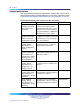
An Introduction to IP Routing Protocols Class Address Range D 224.0.0.0 239.255.255.254 Mask Number of Networks Nodes per Network Note: Class D addresses are primarily reserved for multicast operations although the addresses 224.0.0.5 and 224.0.0.6 are used by OSPF and 224.0.0.9 is used by RIP. E 240.0.0.0 240.255.255.255 Note: Class E addresses are reserved for research purposes.
IP routing 15 A subnet address is created by increasing the network portion to include a subnet address, thus decreasing the host portion of the IP address. For example, in the address 128.32.10.0, the network portion is 128.32, while the subnet is found in the first octet of the host portion (10). A subnet mask is applied to the IP address and identifies the network and host portions of the address.
An Introduction to IP Routing Protocols Variable-length subnet masking (VLSM) is the ability to divide an intranet into pieces that match network requirements. Routing is based on the longest subnet mask or network that matches. IP routing using VLANs The Nortel Ethernet Routing Switch 5500 Series supports wire-speed IP routing between virtual LANs (VLAN). This type of routing is also referred to as virtual routing.
IP routing 17 As with any IP address, virtual router interface addresses are also used for device management. For management over IP, any virtual router interface IP address can be used to access the switch as long as routing is enabled. When the Nortel Ethernet Routing Switch 5500 Series switch or stack is used without routing enabled, the Management VLAN is reachable only through the switch or stack IP address.
An Introduction to IP Routing Protocols Network with Multinetting You can configure a static route with the next hop on the secondary interface. You can also add static ARP for a given IP address in the same subnet of a secondary interface.
IP routing 19 If secondary interfaces are configured on the management VLAN, routing cannot be disabled globally or on the management VLAN.
An Introduction to IP Routing Protocols Management VLAN Prior to Software Release 4.0, the Management VLAN was the only VLAN that was used to carry the management traffic, including Telnet, Web, SNMP, BootP and TFTP for the switch. The Management VLAN always exists on the switch and cannot be removed. All IP settings, including switch IP address, stack IP address, subnet mask and default gateway, apply only to the Management VLAN.
IP routing Step Action 1 Enable IP routing globally. 2 Assign an IP address to the specific VLAN or brouter port. 3 Enable IP routing on the interface. 21 —End— Refer to subsequent chapters in this document for detailed instructions on configuring IP routes. Address Resolution Protocol (ARP) Address Resolution Protocol (ARP) Network stations using the IP protocol need both a physical address and an IP address to transmit a packet.
An Introduction to IP Routing Protocols Proxy Address Resolution Protocol (Proxy ARP) Proxy ARP allows a network station to respond to an ARP request from a locally attached host or end station for a remote destination. It does so by sending an ARP response back to the local host with its own MAC address of the network station interface for the subnet on which the ARP request was received. The reply is generated only if the switch has an active route to the destination network.
IP routing 23 Non-local static routes The Nortel Ethernet Routing Switch 5500 Series supports the usage of non-local static routes. A non-local static route is almost identical to a static route with the exception that the next hop of the route is not directly connected to the network entity. Non-local static routes are useful in situations where there are multiple paths to a network and the number of static routes could be reduced by using only one route with a remote gateway.
An Introduction to IP Routing Protocols 3. The neighbors will send their routing tables and the new router will update its routing table based on the advertisements received. 4. From now on periodic updates are send by each router in the network to ensure a correct routing database. If a router does not receive an update from another router within a timeout period, it deletes the routes served by the nonupdating router from its routing table.
IP routing • subnet mask (RIP version 2) • routing table update based on the received RIP message • global update timer • holddown timer and timeout timer per device and per interface • cost per device and per interface 25 The Nortel Ethernet Routing Switch 5500 Series implementation of RIP also supports the following features: • in and out routing policies • auto-aggregation (also known as auto-summarization) of groups of adjacent routes into single entries Many RIP features are configurabl
An Introduction to IP Routing Protocols RIP Send and Receive Modes RIP can be configured to use a number of different send and receive modes depending on the specifics of the network configuration. The following table lists the send and receive modes supported. RIP send and receive modes Send Mode Description Result rip1comp This mode is used to broadcast RIP version 2 updates using RFC 1058 route consumption rules. This is the default send mode for the Nortel Ethernet Routing Switch 5500 Series.
IP routing rip1OrRip2 RIP version 1 or RIP version 2 updates are accepted. rip1 RIP version 1 and RIP version 1 compatible updates only are accepted. rip2 RIP version 2 updates only are accepted. 27 Limitations RIP has the following limitations: • The protocol is limited to networks whose longest path is 15 hops. • The protocol depends on counting to infinity to resolve certain unusual situations.
An Introduction to IP Routing Protocols Benefits Benefits in large networks OSPF offers the following benefits: • Fast convergence In the event of topological changes, OSPF recalculates routes quickly. • Minimal routing protocol traffic Unlike distance vector routing protocols such as RIP, OSPF generates a minimum of routing protocol traffic. • Load sharing OSPF provides support for equal-cost multipath routing.
IP routing 29 8. From this database each router calculates a shortest-path tree, with itself as root. This shortest-path tree in turn yields a routing table for the protocol. OSPF router types Routers in an OSPF network can take on different roles depending their configuration. The following table describes the router types in an OSPF network.
An Introduction to IP Routing Protocols Host routes are managed with Nortel Networks Command Line Interface (NNCLI) commands and SNMP MIBs and are identified by the host IP address and the configured route type of service (TOS). For each host directly connected to the router, configure the cost of the link to the host during host creation. You cannot modify this cost. Note: Always set TOS to 0 because TOS-based routing is not supported.
IP routing 31 Creating Host Route Example : 1 R3(config)#router ospf R3(config-router)#host-route 11.11.11.111 metric 10 R3(config-router)#show ip ospf host-route Host IP Metric 11.11.11.111 10 R3(config-router)# The following is an example for deleting a host route: Deleting Host Route Example : 1 R3(config-router)#no host-route 11.11.11.
An Introduction to IP Routing Protocols Virtual link diagram Note: Stub or NSSA areas cannot be transit areas. A virtual link can be created manually or automatically. Manual virtual link creation can conserve resources and provide specific control of virtual link placement in the OSPF configuration. To add a virtual link manually, configure both endpoint ABRs with a neighbor router ID and transit area ID. You can configure up to 16 virtual links.
IP routing 33 In this case, R4 in Area2 cannot be physically connected to Area0 (for some reason) and it will be connected to R3 which is NOT a backbone ABR (like R1 is for instance). As Area2 is not directly connected to backbone Area0 or directly connected to a backbone ABR router, clients from Area2 will not be able to access anything outside Area2. Also, router R3 is an ABR router connected to two non-backbone areas.
An Introduction to IP Routing Protocols OSPF Traps: Disabled Auto Virtual Link Creation: Enabled SPF Hold-Down Time: 10 RFC 1583 Compatibility: Enabled R3 (config-router)#auto-vlink Example : 2 R3(config)#show ip ospf Router ID: 3.0.1.
IP routing 35 Router ID: 3.0.1.
An Introduction to IP Routing Protocols Route policies supports the following types of policies: • Accept (In) Policies Accept polices are applied to incoming routing updates before they are applied to the routing table. In the case of RIP, accept policies can be applied to all incoming packets and only one policy can be created for each RIP interface. In the case of OSPF, accept policies are only applied to Type 5 External routes based on the advertising router ID.
IP routing 37 To configure routing policies, create the appropriate prefix lists and then assign those prefix lists to route maps. Once all route maps have been created, assign them to the appropriate type of policy. In a stacked environment, the following rules are applied to routing policies: • The policy database is stored in all stack units. • Policy configuration is supported from only the base unit. The base unit sends updates to non-base units to update the policy database in each stack unit.
An Introduction to IP Routing Protocols Equal Cost MultiPath (ECMP) The Equal Cost MultiPath (ECMP) feature allows routers to determine equal cost paths to the same destination prefix. The multiple paths can be used for load sharing of traffic and allows faster convergence to other active paths in case of network failure. By maximizing load sharing among equal-cost paths, links between routers can be used more efficiently when sending IP traffic.
IP routing 39 For each ingress interface and protocol, the UDP broadcast packets are forwarded only to a unicast host address (the unicast IP address of the server for example). Dynamic Host Configuration Protocol (DHCP) / Bootstrap Protocol (BootP) DHCP-BootP relay The Dynamic Host Configuration Protocol (DHCP) is an extension of the Bootstrap protocol (BootP) and provides host configuration information to workstations on a dynamic basis.
An Introduction to IP Routing Protocols "DHCP operation" (page 40)Figure DHCP operation shows an end station connected to subnet 1, corresponding to VLAN 1. The Nortel Ethernet Routing Switch 5500 Series connects two subnets by means of the virtual routing function. When the end station generates a DHCP request as a limited UDP broadcast to the IP address of all 1s (that is, 255.255.255.
IP routing 41 If a DHCP client is connected to a routable interface, to configure DHCP requests to be sent to up to 512 different routable interfaces or 512 different server IP addresses, enable DHCP on the client (agent address) and then enable DHCP from the client to each of the interfaces or IP addresses (server addresses). In the example shown in "Multiple BootP/DHCP servers" (page 41), two DHCP servers are located on two different subnets.
An Introduction to IP Routing Protocols Any of the Nortel Ethernet Routing Switch 5500 Series switch management systems can be used to set DHCP. DHCP relay DHCP (Dynamic Host Configuration Protocol) is a mechanism to assign network IP addresses to clients who request an address. It is built on top of the existing BOOTP protocol and can be specified for DHCP, BOOTP, or both. The DHCP relay feature relays client requests to DHCP servers on different L3 VLANs.
IP routing 43 These commands must be executed in the Global Configuration command mode. Interface DHCP relay configurations These configurations are associated with the L3 VLAN that the client or server resides on. IP routing must be enabled and a valid IP address must be assigned to the L3 VLAN before it generates the default settings for DHCP relay. "Interface DHCP relay commands" (page 43)describes the interface DHCP relay commands.
An Introduction to IP Routing Protocols DHCP relay uses a hardware resource that is shared by switch Quality of Service applications. When DHCP relay is enabled globally, the Quality of Service filter manager will not be able to use precedence 11 for configurations. For the filter manager to be able to use this resource, DHCP relay must be disabled for the entire unit or stack.
IP routing 45 IP blocking IP Blocking is a Layer 3 feature of the Nortel Ethernet Routing Switch 5500 Series that provides built-in safeguards for the usage of duplicate IP addresses in a stacked environment. IP Blocking is used whenever a unit leaves a stack or is rebooting inside the context of a stack. Depending on the setting in use, Layer 3 functionality is either continued or blocked by this feature. IP Blocking can exist in either a none or full condition.
An Introduction to IP Routing Protocols — The stack will continue to run normally with the base unit controlling Layer 3 and DRP functionality. — If the non-operational non-base unit does not rejoin the stack, no Layer 3 or DRP functionality will run on it.
IGMP snooping 47 "IP multicast propagation with IGMP routing" (page 47)shows how IGMP is used to set up the path between the client and server. As shown in this example, the IGMP host provides an IP Multicast stream to designated routers that forward the IP Multicast stream on their local network only if there is a recipient. The client/server path is set up as follows: 1.
An Introduction to IP Routing Protocols The Nortel Ethernet Routing Switch 5500 Series can automatically set up IP Multicast filters so the IP Multicast traffic is only directed to the participating end nodes (see ). In , "5500 Series switch filtering IP multicast streams (1 of 2)" (page 48)switches S1 to S4 represent a LAN connected to an IP Multicast router. The router periodically sends Host Membership Queries to the LAN and listens for a response from end stations.
IGMP snooping 49 5500 Series switch filtering IP multicast streams (2 of 2) The consolidated proxy report generated by the switch remains transparent to Layer 3 of the International Standardization Organization, Open Systems Interconnection (ISO/OSI) model. (The switch IP address and MAC address are not part of proxy report generation.) The last reporting IGMP group member in each VLAN represents all of the hosts in that VLAN and IGMP group.
An Introduction to IP Routing Protocols • The snooping field must be enabled for the proxy field to have any valid meaning. • Static router ports are configured per VLAN and per IGMP Version. Note: Because IGMP snooping is set up per VLAN, all IGMP changes are implemented according to the VLAN configuration for the specified ports. Nortel Ethernet Routing Switch 5500 Series Configuration-IP Routing Protocols NN47200-503 03.01 Standard 5.1 27 August 2007 Copyright © 2005-2007, Nortel Networks .
IP Routing Configuration and Management This chapter describes the configuration and management of IP routing in the Nortel Ethernet Routing Switch 5500 Series. IP Routing configuration is accomplished through the Command Line Interface (CLI), Web-based Management Interface, or the Java Device Manager (JDM).
IP Routing Configuration and Management Open Shortest Path First (OSPF) initial configuration This section contains the steps necessary for the initial configuration of OSPF on the switch. More advanced configuration examples can be found in the "IP routing configuration examples" (page 120)section. Basic OSPF configuration A basic OSPF configuration will learn OSPF routes from other OSPF devices and propagate routes to other OSPF devices.
IP routing initial configuration 9 53 Assign an IP address to VLAN 35. 5530-24TFD(config-if)# ip address 1.1.2.25 255.255.255.0 10 Enable OSPF in VLAN 35. 5530-24TFD(config-if)# ip ospf en 11 Return to Global Configuration mode. 5530-24TFD(config-if)# exit 12 By default all ports belong to a newly created VLAN. This command removes all of the ports from VLAN 35 . 5530-24TFD(config)# vlan members remove 35 all 13 Add ports 1 through 10 to VLAN 35.
IP Routing Configuration and Management 3 Log into the OSPF router configuration mode. 5530-24TFD(config)# router ospf 4 Enable ASBR functionality. 5530-24TFD(config-router)# as-boundary-router en 5 Use the following commands to select the type of routes that OSPF will distribute to other OSPF devices. RIP, direct, and static routes are supported.
IP routing configuration using the CLI 55 This command tells the router to use up to two paths to get to any OSPF network destination. 4 The configuration can be verified using the following command. 5530-24TFD(config)# show ecmp —End— IP routing configuration using the CLI This section describes the various Command Line Interface commands available for the configuration and management of IP routing.
IP Routing Configuration and Management ip blocking-mode parameters Parameter Description full Select this parameter to set IP blocking to full. This never allows a duplicate IP address in a stack. none Select this parameter to set IP blocking to none. This allows duplicate IP addresses unconditionally. This command is executed in the Global Configuration command mode. Layer 3 routable VLANs The Nortel Ethernet Routing Switch 5500 Series are Layer 3 (L3) switches.
IP routing configuration using the CLI 57 ip address parameters Parameter Description The IP address to attach to the VLAN. The subnet mask to attach to the VLAN <1 - 256> The MAC offset value. Specify the value 1 for the Management VLAN only. secondary Use this option to set up a secondary IP interface on a VLAN. You can have a maximum of eight secondary IP interfaces for every primary and the primary must be set up before any secondary interfaces are configured.
IP Routing Configuration and Management ip address [] secondary —End— Example Adding secondary IP interfaces to a VLAN Primary and secondary interfaces must reside on different subnets. In the following example, 4.1.0.10 is the primary IP and 4.1.1.10 is the secondary IP. interface vlan 4 ip address 4.1.0.10 255.255.255.0 6 ip address 4.1.0.10 255.255.255.
IP routing configuration using the CLI 59 The syntax for the show vlan ip command is: show vlan ip [vid <1 - 4094>] Substitute <1 - 4094> above with the VLAN ID of the VLAN to be displayed. Static route commands This section discusses the commands used to display and configure static routes on the Nortel Ethernet Routing Switch 5500 Series. show ip route static command The show ip route static command displays all static routes, whether these routes are active or inactive.
IP Routing Configuration and Management 10.3.2.0 255.255.255.0 10.3.2.199 1 1 ---- C DB 0 Total Routes: 3 TYPE Legend: I=Indirect Route, D=Direct Route, A=Alternative Route, B=Best Route, E=Ecmp Route, U=Unresolved Route, N=Not in HW The following table outlines the parameters for this command. show ip route parameters Parameter Description Enter IP address to display the route for the specific IP address. Enter subnet mask address for the subnet to display.
IP routing configuration using the CLI 61 ip route parameters Parameter Description Enter IP address of the destination point of the route being added. Enter subnet mask address of the destination node for the route being added. Enter the IP address of the next hop of the route being added. <1 - 65535> Enter the weight, or cost, of the route being added. The ip route command is executed in the Global Configuration command mode.
IP Routing Configuration and Management ip route enable parameters Parameter Description Enter IP address of the destination point of the route being enabled. Enter subnet mask address of the destination node for the route being enabled. Enter the IP address of the next hop of the route being enabled. The ip route enable command is executed in the Global Configuration command mode. ip route disable command The ip route disable command disables a static route.
IP routing configuration using the CLI 63 traceroute <-m> <-p> <-q> <-v> <-w> <1-1464> The following table describes the parameters for this command. traceroute parameters Parameter Description Hostname Enter the name of the remote host. A.B.C.D. Enter the A.B.C.D. name of the remote host. ip Enter the IP address of the remote host. -m Specifies the maximum time to live (ttl). The value for this parameter is in the rage from 1-255. The default value is 10.
IP Routing Configuration and Management Parameter Description Enter the IP address of the next hop of the route being modified. <1 - 65535> Enter the new weight, or cost, of the static route. The ip route weight command is executed in the Global Configuration command mode. Address Resolution Protocol (ARP) commands Use the CLI to display, create, configure, and remove ARP entries. show arp command The show arp-table command displays ARP entries.
IP routing configuration using the CLI 65 The show ip arp command is executed in the Global Configuration command mode. show ip arp static command The show ip arp static command displays all configured static entries in an ARP table, including those without a valid route. The syntax for the show ip arp static command is: show ip arp static The show ip arp static command can be executed in any command mode.
IP Routing Configuration and Management no ip arp command The no ip arp command removes an ARP entry. The syntax for the no ip arp command is: no ip arp Substitute above with the IP address of the static ARP entry to remove. The no ip arp command is executed in the Global Configuration command mode. ip arp timeout command The ip arp timeout command configures an aging time for the ARP entries.
IP routing configuration using the CLI 67 no ip arp-proxy [enable] The no ip arp-proxy command is executed in the Layer 3 IP VLAN Interface Configuration mode. default ip arp-proxy command The default ip arp-proxy command is used to return the switch to the default proxy ARP settings. The syntax of the default ip arp-proxy command is: default ip arp-proxy [enable] The default ip arp-proxy command is executed in the Layer 3 IP VLAN Interface Configuration mode.
IP Routing Configuration and Management router rip command The router rip command is used to enter the Router Configuration mode for RIP. Router Configuration mode is used to configure various aspects of RIP, OSPF (router ospf command), and VRRP (router vrrp command). The syntax of the router rip command is: router rip The router rip command is executed in the Global Configuration command mode. network command The network command is used to enable RIP on an IP interface.
IP routing configuration using the CLI 69 The timers basic holddown command is executed in the Router Configuration mode. timers basic timeout command The timers basic timeout command is used to set the RIP timeout timer. The syntax of the timers basic timeout command is: timers basic timeout The parameter represents a value between 15 and 259200 seconds. The timers basic timeout command is executed in the Router Configuration mode.
IP Routing Configuration and Management no ip rip advertise-when-down command The ip rip advertise-when-down command is used to disable RIP advertisements on the interface being configured even when that interface is not operational. The syntax of the no ip rip advertise-when-down command is: no ip rip advertise-when-down {enable} The no ip rip advertise-when-down command is executed in the Interface Configuration mode.
IP routing configuration using the CLI 71 The ip rip cost command is executed in the Interface Configuration mode. ip rip default-listen command The ip rip default-listen command is used to enable the acceptance of default route advertisements. The syntax of the ip rip default-listen command is: ip rip default-listen {enable} The ip rip default-listen command is executed in the Interface Configuration mode.
IP Routing Configuration and Management ip rip holddown command The ip rip holddown command is used to set the value of the holddown timer on the RIP interface. The syntax of the ip rip holddown command is: ip rip holddown The parameter is an integer value between 0 and 360 seconds. The ip rip holddown command is executed in the Interface Configuration mode. ip rip in-policy command The ip rip in-policy command is used to add an in policy to this RIP interface.
IP routing configuration using the CLI 73 ip rip listen {enable} The ip rip listen command is executed in the Interface Configuration mode. no ip rip listen command The no ip rip listen command is used to prevent this interface from listening for RIP advertisements. The syntax of the no ip rip listen command is: ip rip listen {enable} The no ip rip listen command is executed in the Interface Configuration mode.
IP Routing Configuration and Management ip rip poison {enable} The ip rip poison command is executed in the Interface Configuration mode. no ip rip poison command The no ip rip poison command is used to disable poison reverse on this RIP interface. The syntax of the no ip rip poison command is: no ip rip poison {enable} The no ip rip poison command is executed in the Interface Configuration mode.
IP routing configuration using the CLI 75 The parameter indicates the RIP version. The valid values for this parameter are: • rip1 • rip1orrip2 • rip2 The ip rip receive command is executed in the Interface Configuration mode. ip rip send command The ip rip send command is used to set the RIP version sent on this interface. The syntax of the ip rip send command is: ip rip send version The parameter indicates the RIP version.
IP Routing Configuration and Management The no ip rip supply command is executed in the Interface Configuration mode. ip rip timeout command The ip rip timeout command is used to set the RIP timeout value on this interface. The syntax of the ip rip timeout command is: ip rip timeout The parameter is an integer value between 15 and 259200 seconds. The default timeout value is 180 seconds. The command is executed in the Interface Configuration mode.
IP routing configuration using the CLI 77 Use the interface key word to display RIP statistics by interface. Omission of this key word displays general RIP information The show ip rip command is executed in the Global Configuration mode. default router rip command The default router rip command is used to return the switch to the default global RIP state (disabled).
IP Routing Configuration and Management default timers basic update command The default timers basic update command is used to return the switch to the factory default RIP update timer. The syntax of the default timers basic update command is: default timers basic update The default timers basic update command is executed in the Router Configuration mode. default-metric command The default-metric command is used to set the default RIP metric value.
IP routing configuration using the CLI 79 default ip rip cost command The default ip rip cost command is used to restore the default RIP costing settings for the interface. The syntax of the default ip rip cost command is: default ip rip cost [[out-policy ] | [poison enable] | [proxy-announce enable] | [receive ] | [send ] | [supply enable] | [timeout] | [triggered enable]] The default ip rip cost command is executed in the Interface Configuration mode.
IP Routing Configuration and Management default ip rip holddown command The default ip rip holddown command is used to restore the default RIP holddown setting for the interface. The syntax of the default ip rip holddown command is: default ip rip holddown The default ip rip holddown command is executed in the Interface Configuration mode. default ip rip in-policy command The default ip rip in-policy command is used to delete the in policy associated with this interface.
IP routing configuration using the CLI 81 default ip rip poison enable The default ip rip poison command is executed in the Interface Configuration mode. default ip rip proxy-announce command The default ip rip proxy-announce command is used to disable proxy announcement on the interface. The syntax of the default ip rip proxy-announce command is: default ip rip proxy-announce enable The default ip rip proxy-announce command is executed in the Interface Configuration mode.
IP Routing Configuration and Management default ip rip timeout command The default ip rip timeout command is used to restore the default RIP timeout setting for the interface. The syntax of the default ip rip timeout command is: default ip rip timeout The default ip rip timeout command is executed in the Interface Configuration mode. default ip rip triggered command The default ip rip triggered command is used disabled triggered updates on this switch.
IP routing configuration using the CLI 83 The ip ospf apply accept command is executed in the Global Configuration mode. ip ospf apply redistribute direct command The ip ospf apply redistribute direct command is used to apply only direct OSPF redistribution configuration to the switch. The syntax of the ip ospf apply redistribute direct command is: ip ospf apply redistribute direct The ip ospf apply redistribute direct command is executed in the Global Configuration mode.
IP Routing Configuration and Management router ospf enable command The router ospf enable command is used to enable OSPF globally on the switch. The syntax of the router ospf enable command is: router ospf enable The router ospf enable command is executed in the Global Configuration mode. no router ospf enable command The no router ospf enable command is used to disable OSPF globally on the switch.
IP routing configuration using the CLI 85 accept adv-rtr [enable] [metric-type {any | type1 | type2}] [route-policy {policy_name}] The following table outlines the parameters for this command. accept adv-rtr parameters Parameter Description router_ip_address This parameter represents the IP address of the router advertisements will be accepted from. The value 0.0.0.0 denotes that advertisements from all routers will be accepted.
IP Routing Configuration and Management [advertise-mode {no-summarize | summarize | suppress}] [advertise-metric {0-65535}]] The following table outlines the parameters for this command. area parameters Parameter Description ip_address Specifies the Area ID expressed as IP address (A.B.C.D). default-cost {0-16777215} The default cost associated with an OSPF stub area. import {external | noexternal | nssa} The area’s support for importing Autonomous System external link state advertisements.
IP routing configuration using the CLI 87 no area parameters Parameter Description ip_address Specifies the Area ID expressed as IP address (A.B.C.D). import-summaries {enable} Controls the import of summary link state advertisements into stub areas. This setting has no effect on other areas. range {subnet_mask} {nssa-entlink | summary-link} Used to specify range parameters for the OSPF area. The no area command is executed in the Router Configuration mode.
IP Routing Configuration and Management The parameter represents the cost value to assign to the port. This value is an integer between 1 and 65535. The default-cost ethernet command is executed in the Router Configuration mode. default-cost fast-ethernet command The default-cost fast-ethernet command is used to define the default cost metric of a fast ethernet (100 Mbps) port.
IP routing configuration using the CLI 89 host-route command Use the host-route command to add a host to a router. For more information about host routes, see "OSPF host route" (page 29). The syntax for the host-route command is: host-route metric <0-65535> where is the host IP address and metric is an integer between 0 and 65535 representing the configured cost of the host The host-route command is executed in the Router Configuration mode.
IP Routing Configuration and Management no network The parameter represents the IP address of the interface to be disabled. The no network command is executed in the Router Configuration mode. redistribute command The redistribute command is used to configure OSPF route redistribution. Direct, RIP, and static route redistribution is currently supported.
IP routing configuration using the CLI 91 no redistribute parameters Parameters Description The type of route to be configured. Valid options are direct, rip, and static. The route policy to remove from the route redistribution. This is the name of an existing route policy. The no redistribute command is executed in the Router Configuration mode.
IP Routing Configuration and Management The syntax of the no router-id command is: no router-id The no router-id command is executed in the Router Configuration mode. timers basic holddown command The timers basic holddown command is used to configure the OSPF holddown timer. The syntax of the timers basic holddown command is: timers basic holddown The parameter represents a second value between 3 and 60 seconds. The command is executed in the Router Configuration mode.
IP routing configuration using the CLI 93 area virtual-link parameters Parameter Description Specifies the transit area ID expressed as an IP address. Specifies the neighbor router ID expressed as an IP address. authentication-key Specifies the unique identifier assigned to the authentication key.
IP Routing Configuration and Management no area virtual-link [authenticationkey] no area virtual-link command parameters Parameter Description Specifies the transit area Id expressed as an IP address. Specifies the neighbor router ID expressed as an IP address. authentication-key Specifies the unique identifier assigned to the authentication key The no area virtual-link command is executed in the Router Configuration mode.
IP routing configuration using the CLI 95 no area virtual-link message-digest-key <1-255> no area virtual-link message-digest-key command parameters Parameter Description Specifies the transit area ID expressed as an IP address. Specifies the neighbor router ID expressed as an IP address. <1-255> Specifies the primary MD5 key value, expressed as an integer from 1-255.
IP Routing Configuration and Management ip ospf area command The ip ospf area command is used to assign an interface to an OSPF area. The syntax of the ip ospf area command is: ip ospf area The parameter represents the unique ID of the area to which the interface connects. An area ID of 0.0.0.0 indicates the OSPF area backbone and is created automatically by the switch. The ip ospf area command is executed in the Interface Configuration mode.
IP routing configuration using the CLI 97 The ip ospf cost command is executed in the Interface Configuration mode. ip ospf dead-interval command The ip ospf dead-interval command is used to configure a dead interval for the interface. This is the interval of time that a Hello packet has not been transmitted from this interface before its neighbors declare it down.
IP Routing Configuration and Management ip ospf network {broadcast | passive} The ip ospf network command is executed in the Interface Configuration mode. ip ospf primary-md5-key command The ip ospf primary-md5-key command is used to configure the primary MD5 key to use for authentication in instances where interface authentication uses an MD5 key.
IP routing configuration using the CLI 99 ip ospf transmit-delay command The ip ospf transmit-delay command is used to define the transmit delay for this OSPF interface. The syntax of the ip ospf transmit-delay command is: ip ospf transmit-delay The parameter is the transmit delay in seconds. This is an integer value between 0 and 3600. The ip ospf transmit-delay command is executed in the Interface Configuration mode.
IP Routing Configuration and Management Command Description show ip ospf area-range Displays configuration information about the OSPF area range specified in the parameter. Omitting this parameter displays information for all OSPF area ranges. show ip ospf ase Displays information about the OSPF Autonomous System external links state advertisements. show ip ospf default Displays OSPF default metrics associated with various port types.
IP routing configuration using the CLI 101 Command Description show ip ospf virtual-neighbors Displays general information about virtual neighbors. show ip ospf host-route Displays the host IP address and cost for a host route. clear ip ospf counters command The clear ip ospf counters command clears OSPF statistics counters, including mismatch counters. TIP: If no VLAN is specified, the command clears OSPF global counters.
IP Routing Configuration and Management ip prefix-list parameters Parameter Description The name assigned to the prefix list. The IP address and subnet mask of the prefix list. The subnet mask is expressed as a value between 0 and 32. The subnet range covered by the prefix list from the stated IP address. The subnet range covered by the prefix list to the stated IP address.
IP routing configuration using the CLI 103 Indicates a previously defined prefix list to be used with the command. This parameter is used with various options in this command. The name of a protocol to be used. Options are direct, static, rip, ospf, and any. Multiple protocols can be specified by using a comma-separated list. A route type to be used. Options are any, external, external-1, external-2, internal, and local.
IP Routing Configuration and Management The ip rip out-policy command is executed in the Interface Configuration mode. Virtual Router Redundancy Protocol (VRRP) commands The Virtual Router Redundancy Protocol (VRRP) is designed to eliminate the single point of failure that can occur when the single static default gateway router for an end station is lost. This section describes the CLI commands used to configure VRRP.
IP routing configuration using the CLI 105 ping-virtual-address enable The ping-virtual-address enable command is executed in the Router Configuration mode. no ping-virtual-address enable command The no ping-virtual-address enable command is used to disable ICMP echo replies from VRRP associated addresses. The syntax of the no ping-virtual-address enable command is: no ping-virtual-address enable The no ping-virtual-address enable command is executed in the Router Configuration mode.
IP Routing Configuration and Management The ip vrrp address command is executed in the Interface Configuration mode. no ip vrrp address command The no ip vrrp address command is used to delete the association of an IP address with a virtual router ID. The syntax of the no ip vrrp address command is: no ip vrrp address The parameter represents the virtual router being configured. This is a value between 1 and 255.
IP routing configuration using the CLI 107 ip vrrp backup-master command The ip vrrp backup-master command is used to enable the VRRP backup / master functionality. The syntax of the ip vrrp backup-master command is: ip vrrp backup-master enable The parameter represents the virtual router being configured. The ip vrrp backup-master command is executed in the Interface Configuration mode.
IP Routing Configuration and Management The no ip vrrp critical-ip command is executed in the Interface Configuration mode. ip vrrp critical-ip-addr command The ip vrrp critical-ip-addr command is used to set the IP address used with the VRRP critical IP functionality. The syntax of the ip vrrp critical-ip-addr command is: ip vrrp critical-ip-addr The parameter represents the virtual router being configured.
IP routing configuration using the CLI 109 The parameter represents the virtual router being configured. The ip vrrp fast-adv command is executed in the Interface Configuration mode. no ip vrrp fast-adv command The no ip vrrp fast-adv command is used to disable the VRRP fast advertisement functionality. The syntax of the no ip vrrp fast-adv command is: no ip vrrp fast-adv enable The parameter represents the virtual router being configured.
IP Routing Configuration and Management ip vrrp priority command The ip vrrp priority command is used to assign a priority to a virtual router. The syntax of the ip vrrp priority command is: ip vrrp priority The parameter represents the virtual router being configured. The parameter represents the priority assigned to the virtual router. This is a value between 1 and 255. The ip vrrp priority command is executed in the Interface Configuration mode.
IP routing configuration using the CLI 111 The parameter represents the number of ECMP paths allotted. This is a value between 1 and 4. The default is 1. The rip maximum-path command is executed in the Global Configuration mode. ospf maximum-path command The ospf maximum-path command is used to configure the number of ECMP paths allotted for the Open Shortest Path First (OSPF) protocol.
IP Routing Configuration and Management Brouter port commands A brouter port is a single-port VLAN that can route IP packets as well as bridge all non-routable traffic. The following section describes the CLI commands used to configure and manage brouter ports on the Nortel Ethernet Routing Switch 5500 Series. brouter command The brouter command is used to create and manage a brouter port on the switch.
IP routing configuration using the CLI 113 show brouter command The show brouter command is used to display information about the brouter configuration on the switch. The syntax of the show brouter command is: show brouter [port ] Usage of the optional port port narrows the scope the command to the specified port. Omission of this parameter displays all ports. The show brouter command is executed in the User EXEC mode.
IP Routing Configuration and Management clear ip forward-protocol udp counters command The clear ip forward-protocol udp counters command clears the UDP broadcast counters on each interface. TIP: Stacking - the clear ip forward-protocol udp counters command is executed only on the base unit in a stack. The syntax for the clear ip forward-protocol udp counters command is: clear ip forward-protocol udp counters <1-4094> where the parameter <1-4094> specifies the VLAN ID.
IP routing configuration using the CLI 115 DHCP relay commands This section covers the commands that are used to configure and manage DHCP on the Nortel Ethernet Routing Switch 5500 Series, both globally on the switch and on each VLAN. Setting DHCP To set DHCP, perform the following procedure: Step Action 1 Enable DHCP globally. 2 Set a VLAN IP as the DHCP agent and a Server IP as the DHCP server, to configure an ip dhcp-relay forwarding path. 3 Set the mode for each DHCP forwarding path.
IP Routing Configuration and Management show ip dhcp-relay counters command The show ip dhcp-relay counters command displays the current DHCP relay counters configuration globally on the Nortel Ethernet Routing Switch 5500 Series. This includes the number of requests and the number of replies. The syntax for the show ip dhcp-relay counters command is: show ip dhcp-relay counters The show ip dhcp-relay counters command is executed in the User EXEC command mode.
IP routing configuration using the CLI 117 ip dhcp-relay fwd-path parameters Parameter Description Enter the IP address of the DHCP agent on the forwarding path to be configured. Enter the IP address of the DHCP server on the forwarding path to be configured. The ip dhcp-relay fwd-path command is executed in the Global Configuration command mode. The DHCP relay feature is enabled by default, and the default mode is BootP-DHCP.
IP Routing Configuration and Management The following table describes the parameters for this command. ip dhcp-relay fwd-path disable parameters Parameter Description Enter the IP address of the DHCP agent on the forwarding path to be disabled. Enter the IP address of the DHCP server on the forwarding path to be disabled. The ip dhcp-relay fwd-path disable command is executed in the Global Configuration command mode. The DHCP relay feature is enabled by default.
IP routing configuration using the CLI 119 The show vlan dhcp-relay command is executed in the User EXEC command mode. ip dhcp-relay command The ip dhcp-relay command allows configures DHCP relay settings on a VLAN. The syntax for the ip dhcp-relay command is: ip dhcp-relay [min-sec <0-65535>] [mode {bootp | dhcp | bootp_dhcp}] The following table outlines the parameters for this command.
IP Routing Configuration and Management ip dhcp-relay broadcast The ip dhcp-relay broadcast command is executed in the Interface Configuration command mode. no ip dhcp-relay broadcast command The no ip dhcp-relay broadcast command disables DHCP relay broadcast on a VLAN. The syntax for the no ip dhcp-relay broadcast command is: no ip dhcp-relay broadcast The no ip dhcp-relay broadcast command is executed in the Interface Configuration command mode.
IP routing configuration examples 121 This section contains the following topics: • "Changing the default ARP aging time" (page 121) • "Adding a static ARP entry to a VLAN" (page 121) • "Adding a static ARP entry to a brouter port" (page 122) • "Deleting a static ARP entry" (page 122) Changing the default ARP aging time The default ARP aging time value is set for 360 minutes. To change this default aging time use the ip arp timeout command.
IP Routing Configuration and Management Adding a static ARP entry to a brouter port To add a static ARP entry to a brouter port, use the ip arp command. This command has the following syntax: ip arp ip mac port vid The following table outlines the parameters of this command ip arp parameters Parameter Description ip_address The IP address of the entry. mac_address The MAC address of the entry.
IP routing configuration examples 123 Note: The command examples below demonstrate the configuration of RIP on a VLAN. Step Action 1 Configure the interface, assign an IP address and add ports. 5530-24TFD# enable 5530-24TFD#config terminal 5530-24TFD(config)# vlan create 51 name "VLAN-51" type port 5530-24TFD(config)# interface vlan 51 5530-24TFD(config-if)# ip address 10.10.1.1 255.255.255.0 5530-24TFD(config-if)# exit 5530-24TFD(config)# vlan members add 51 8-9 2 Enable RIP.
IP Routing Configuration and Management 5530-24TFD(config-if)# ip rip default-supply enable 6 Enable Default Route Listen to add a default route to the route table, if advertised from another router. 5530-24TFD# enable 5530-24TFD# config terminal 5530-24TFD(config)# interface vlan 51 5530-24TFD(config-if)# ip rip default-listen enable 7 Add the In or Out Route Policy.
IP routing configuration examples 125 Therefore, the receiver neighbor ignores this route because the metric 16 indicates infinite hops in the network. These mechanisms prevent routing loops. 5530-24TFD# enable 5530-24TFD# config terminal 5530-24TFD(config)# interface vlan 51 5530-24TFD(config-if)# ip rip 5530-24TFD(config-if)# ip rip poison enable —End— Configuring RIP This section describes the set up of a basic RIP configuration between two Nortel Ethernet Routing Switch 5500 Series routers.
IP Routing Configuration and Management Step Action 1 Configure tagging on ports 1/47 and 1/48. Tagging is required to support multiple VLANs on the same interface. 5530-24TFD# enable 5530-24TFD# config terminal 5530-24TFD(config)# vlan ports 1/47-48 tagging tagAll 2 Configure ERS2 for VLAN 2 access. a. Create a port-based VLAN (VLAN 2) using spanning tree group 1 and include ports 1/47 and 1/48 in VLAN 2.
IP routing configuration examples 127 5530-24TFD(config-if)#ip rip listen disable 4 Configure brouter port 2/7 on ERS2. a. Assign the IP address 10.1.1.1/30 to port 2/7 using brouter VLAN 2090. 5530-24TFD(config)# interface FastEthernet 2/7 5530-24TFD(config-if)# brouter vlan 2090 subnet 10.1.1.1/30 Note: Usage of the brouter command above requires the usage of Variable Length Subnetting. Usage of a dotted decimal subnet mask is not allowed. b. Enable RIP on the interface.
IP Routing Configuration and Management interface vlan 3 no ip rip listen enable no ip rip supply enable ! *** Brouter Port *** ! interface fastEthernet ALL brouter port 2/7 vlan 3 subnet 10.1.1.1/30 The following commands can be used to confirm the configuration of RIP parameters: Command Description show vlan This command is used to display information about the currently configured switch VLANs.
IP routing configuration examples 129 RIPv2 configuration example Use the following procedure to configure ERS2 to add RIP version 2 to VLAN 2, VLAN 3, and the brouter port: Step Action 1 Configure RIP version 2 on VLAN 2. Enable RIP version 2 mode on the IP address used for VLAN 2.
IP Routing Configuration and Management 5530-24TFD(config-if)# ip rip receive version rip2 —End— Using RIP accept policies RIP accept policies are used on the Nortel Ethernet Routing Switch 5500 Series to selectively accept routes from RIP updates. If no policies are defined, the default behavior is applied. This default behavior is to add all learned routes to the route table. RIP accept policies are used to: • Listen to RIP updates only from certain gateways.
IP routing configuration examples 131 Accept policy configuration Use the following steps to recreate the above configuration example: Step Action 1 Configure the IP prefix list on ERS1. Create a prefix list named Prefix_1 with an IP range from 10.1.240.0 to 10.1.255.0. 5530-24TFD(config)# ip prefix-list Prefix_1 10.1.240.0/20 ge 20 le 32 2 Configure the route policy named rip_pol_1 with match criteria using the IP prefix configured in step 1. This injects one route of 10.1.240.
IP Routing Configuration and Management 5530-24TFD(config)# interface FastEthernet 2/8 5530-24TFD(config-if)# brouter vlan 2091 subnet 10.1.1.5/30 5530-24TFD(config-if)# ip rip enable 5530-24TFD(config-if)# ip rip in-policy rip_pol_1 —End— The show running-config command is used to display the current configuration of a switch. Using this command on the above configuration would yield the following results: rip_pol_1 ! *** Route Policies *** ! ip prefix-list Prefix_1 10.1.240.
IP routing configuration examples 133 Step Action 1 Configure the IP prefix list on ERS3 named Prefix_1 with the IP address 10.1.240.0. 5530-24TFD(config)# ip prefix-list Prefix_1 10.1.240.0/20 ge 20 le 32 2 Configure the route policy named Policy_Rip with match criteria using the IP prefix configured in step 1.
IP Routing Configuration and Management 5530-24TFD(config)# route-map rip_pol_2 1 match network Prefix_2 3 Add the Route Policy created in step 2 to both RIP core ports. 5530-24TFD(config)# interface FastEthernet 2/1 5530-24TFD(config-if)# brouter vlan 2091 subnet 10.1.1.14/30 5530-24TFD(config-if)# ip rip enable 5530-24TFD(config-if)#ip rip out-policy rip_pol_2 5530-24TFD(config)# interface FastEthernet 2/8 5530-24TFD(config-if)# brouter vlan 2090 subnet 10.1.1.
IP routing configuration examples 135 To create the OSPF interface illustrated above for router R1, follow this procedure: Step Action 1 Configure brouter port OSPF interface. Configure port 2 as a brouter port with VLAN ID of 2134 and enable OSPF on this interface. 5530-24TFD# config terminal 5530-24TFD(config)# interface fast 2 5530-24TFD(config-if)# brouter port 2 vlan 2134 subnet 10.1.1.21/30 5530-24TFD(config-if)# router ospf 5530-24TFD(config-router)# network 10.1.1.
IP Routing Configuration and Management Simple password mechanism The simple password security mechanism transmits a text password in the OSPF headers. Only routers that contain the same authentication ID in their OSPF headers can communicate with each other. Note: Nortel recommends not using this security mechanism because the password is stored in plain text and can be read from the configuration file or from the OSPF packet.
IP routing configuration examples 137 MD5 configuration example To replicate the above configuration example using the key ID 2 and key value qwsdf89, perform the following steps: Step Action 1 Configure MD5 authentication on R1. 5530-24TFD(config)# interface vlan 2 5530-24TFD(config-if)# ip ospf message-digest-key 2 md5 qwsdf89 5530-24TFD(config-if)# ip ospf primary-md5-key 2 5530-24TFD(config-if)# ip ospf authentication-type message-digest 2 Configure MD5 authentication on R2.
IP Routing Configuration and Management OSPF network example To create the configuration illustrated above for router R1, use the following commands: 5530-24TFD(config)# vlan create 2 type port 5530-24TFD(config)# vlan mem add 2 1 5530-24TFD(config)# interface vlan 2 5530-24TFD(config-if)# ip address 172.3.1.1 255.255.255.
IP routing configuration examples 139 The impact of a topology change is localized to the area in which it occurs. The only exception to this is for the area border routers, which must maintain an LSDB for each area to which they belong. Changes in topology are advertised to the rest of the network by the area border routers by advertising summary LSAs. A 32-bit Area ID, expressed in IP address format such as 0.0.0.0 for 0 identifies areas.
IP Routing Configuration and Management Stub and Not So Stubby areas Stub areas do not receive advertisements for external routes (AS-external LSAs, type 5) from an ABR, which reduces the size of the link state database. Instead, routing to external destinations from within a stub area is based on the default route that is originated by the stub area ABR (Summary LSA, type 3).
IP routing configuration examples 141 OSPF stub area example Note: AS-external LSAs are not flooded into a stub area. Instead, only one default route to external destinations is distributed into the stub area by the stub ABR router. The area default cost specifies the cost for advertising the default route into stub area by the ABR. Use the procedure outlined below to perform the stub area configuration illustrated above: Note: This example assumes that global IP routing has been enabled on the switch.
IP Routing Configuration and Management Configure R1 in stub area 2 with the Router-ID 1.1.1.5. Add the OSPF interfaces to area 2 and enable OSPF on these interfaces. 5530-24TFD(config-router)# 5530-24TFD(config-router)# noexternal 5530-24TFD(config-router)# 0.0.0.2 5530-24TFD(config-router)# 0.0.0.2 5530-24TFD(config)# router 2 router-id 1.1.1.5 area 0.0.0.2 import network 10.1.1.18 area network 172.3.3.1 area ospf enable Configure router R2. a. Configure the OSPF interface on R2.
IP routing configuration examples 143 Not So Stubby Areas (NSSA) Similar to stub areas, the not so stubby area (NSSA) can also prevent the flooding of AS-External Link State advertisements into the NSSA by replacing them with a default route. However, NSSA can also import small stub (non-OSPF) routing domains into OSPF. This allows the NSSA to import external routes, such as RIP routes, and then advertise these routes throughout the network.
IP Routing Configuration and Management 5530-24TFD(config)# interface vlan 100 5530-24TFD(config-if)# ip rip receive version rip2 send version rip2 c. Configure the OSPF interface on R1. Configure port 2/6 as a brouter port in VLAN 200. 5530-24TFD(config)# interface fast 2/6 5530-24TFD(config-if)# brouter port 2/6 vlan 200 subnet 10.1.1.18/30 d. Enable OSPF on R1. Configure R1 as an ASBR, assign OSPF Router-ID 1.1.1.5, create OSPF NSSA area 2, add the OSPF interface 10.1.1.
IP routing configuration examples 145 Configuring Area Border Routers (ABR) Configuration of an OSPF ABR is an automatic process on the Nortel Ethernet Routing Switch 5500 Series; no user intervention is required. The Nortel Ethernet Routing Switch 5500 Series automatically becomes an OSPF ABR when it has operational OSPF interfaces belonging to more than one area.
IP Routing Configuration and Management 3 Enable OSPF. Configure R1 as an ABR. Note that, by default, OSPF interface 10.1.1.22 is placed into OSPF area 0.0.0.0. Because one additional area of 0.0.0.2 is created and OSPF interface 10.1.1.17 is added to area 0.0.0.2, R1 automatically becomes an ABR. 5530-24TFD(config-router)# router-id 1.1.1.2 5530-24TFD(config-router)# area 0.0.0.2 5530-24TFD(config-router)# network 10.1.1.17 area 0.0.0.
IP routing configuration examples 147 Area ID Range Subnet/Mask Range Type Advertise Mode Metric ----------- ------------------ ------------- -------------- -----0.0.0.2 172.3.0.0/16 Summary Link Summarize 100 To display ABR status, use the show ip ospf command. Usage of this command on the example configuration would yield the following output: Router ID: 1.1.1.
IP Routing Configuration and Management ASBR distribution example Use the following procedure to replicate the ASBR distribution example: Step Action 1 Configure RIP. Configure the RIP interface on R1 by configuring port 1/31 as a brouter port in VLAN 100 and enabling RIP on this interface. 5530-24TFD(config)# interface fast 1/31 5530-24TFD(config-if)# brouter port 1/31 vlan 100 subnet 10.1.1.41/30 5530-24TFD(config)# router rip 5530-24TFD(config-router)# network 10.1.1.
IP routing configuration examples 149 5530-24TFD(config-router)# as-boundary-router enable 5530-24TFD(config-router)# router-id 1.1.1.3 5530-24TFD(config)# router ospf enable 5 Configure OSPF route distribution. Configure OSPF route distribution to import RIP into OSPF. The Nortel Ethernet Routing Switch 5500 Series distributes the RIP routes as AS-external LSA (LSA type 5), using external metric type 1.
IP Routing Configuration and Management 2 Configure a route policy. Create a route policy named Policy_Default which distributes the IP prefix list created in step 1. Note that ospf is selected as the match-protocol value. This causes the default route to be advertised through RIP only if OSPF is operational.
IP routing configuration examples 151 External route advertisement example The following procedure outlines the commands used to replicate the above configuration example: Step Action 1 Configure the RIP interface. Configure port 1/20 as a brouter port in VLAN 200 and enables RIP on this interface. 5530-24TFD(config)# interface fast 1/20 5530-24TFD(config-if)# brouter port 1/20 vlan 200 subnet 20.1.1.2/30 5530-24TFD(config)# router rip 5530-24TFD(config-router)# network 20.1.1.
IP Routing Configuration and Management Configure R1 as an ASBR, assign the OSPF Router-ID 1.1.1.5, create OSPF NSSA area 2, add the OSPF interface 10.1.1.18 to area 2, and enable OSPF on the interface. Enable ASBR and OSPF globally. 5530-24TFD(config)# router 5530-24TFD(config-router)# 5530-24TFD(config-router)# 5530-24TFD(config-router)# 5530-24TFD(config-router)# 0.0.0.2 5530-24TFD(config)# router 5 ospf router-id 1.1.1.5 as-boundary-router enable area 0.0.0.2 import nssa network 10.1.1.
IP routing configuration examples 153 Configuring a multi-area complex The multi-area complex configuration example described in this section uses five Nortel Ethernet Routing Switch 5500 Series devices (R1 to R5) in a multi-area configuration. Many of the concepts and topology descriptions that are used in this example configuration are described in the previous sections of this chapter.
IP Routing Configuration and Management • R4 is an OSPF internal router in Area 3. • R5 is an internal OSPF stub router in Area 2. • All interfaces used for this configuration are ethernet, therefore the OSPF interfaces are broadcast. • The interface priority value on R5 is set to 0, therefore R5 cannot become a designated router (DR). • Configure the OSPF Router Priority so that R1 becomes the DR (priority of 100) and R2 becomes backup designated router (BDR) with a priority value of 50.
IP routing configuration examples 155 vlan name 1 "VLAN #1" vlan create 102 name "VLAN #102" type port vlan create 103 name "VLAN #103" type port vlan ports 1-24 tagging unTagAll filter-untagged-frame disable filter-unregistered-frames enable priority 0 vlan ports 25-26 tagging tagAll filter-untagged-frame disable filter-unregistered-frames enable priority 0 vlan members 1 24-26 vlan members 102 1-2 vlan members 103 7-8 vlan ports 1-2 pvid 102 vlan ports 3-6 pvid 1 vlan ports 7-8 pvid 103 vlan ports 9-26 p
IP Routing Configuration and Management enable exit ! *** MLT (Phase 2) *** ! mlt spanning-tree 1 stp 3 learning normal mlt spanning-tree 2 stp 2 learning normal ! *** L3 *** ! no ip directed-broadcast enable ip routing interface vlan 102 ip address 10.1.1.21 255.255.255.252 2 ip dhcp-relay min-sec 0 mode bootp_dhcp no ip dhcp-relay broadcast ip dhcp-relay exit interface vlan 103 ip address 10.1.1.1 255.255.255.
IP routing configuration examples 157 ip ospf dead-interval 40 ip ospf enable exit interface vlan 102 ip ospf area 0.0.0.0 ip ospf network broadcast ip ospf priority 100 ip ospf authentication-type none ip ospf mtu-ignore enable no ip ospf advertise-when-down enable ip ospf enable exit 2.
IP Routing Configuration and Management vlan members 102 1-2 vlan ports 1-2 pvid 102 vlan ports 3-4 pvid 1 vlan ports 5-6 pvid 100 vlan ports 7-8 pvid 101 vlan ports 9-26 pvid 1 vlan igmp unknown-mcast-no-flood disable vlan igmp 1 snooping disable vlan igmp 1 proxy disable robust-value 2 query-interval 125 vlan igmp 100 snooping disable vlan igmp 100 proxy disable robust-value 2 query-interval 125 vlan igmp 101 snooping disable vlan igmp 101 proxy disable robust-value 2 query-interval 125 vlan igmp 10
IP routing configuration examples 159 mlt spanning-tree 1 stp 2 learning normal mlt spanning-tree 2 stp 1 learning normal mlt spanning-tree 2 stp 2 learning normal mlt spanning-tree 5 stp 1 learning normal ! *** L3 *** ! no ip directed-broadcast enable ip routing interface vlan 1 ip dhcp-relay min-sec 0 mode bootp_dhcp no ip dhcp-relay broadcast ip dhcp-relay exit interface vlan 100 ip address 10.1.1.17 255.255.255.
IP Routing Configuration and Management default-cost 1 area 0.0.0.2 import-summaries enable area 0.0.0.3 import external area 0.0.0.3 import-summaries enable exit enable configure terminal interface vlan 101 ip ospf area 0.0.0.
IP routing configuration examples 161 spanning-tree stp 3 create spanning-tree cost-calc-mode dot1d spanning-tree port-mode normal spanning-tree stp 1 priority 8000 spanning-tree stp 1 hello-time 2 spanning-tree stp 1 max-age 20 spanning-tree stp 1 forward-time 15 spanning-tree stp 1 tagged-bpdu disable tagged-bpdu-vid 4001 spanning-tree stp 1 multicast-address 01:80:c2:00:00:00 spanning-tree stp 3 priority 8000 spanning-tree stp 3 hello-time 2 spanning-tree stp 3 max-age 20 spanning-tree stp 3 forward-tim
IP Routing Configuration and Management vlan igmp 103 snooping disable vlan igmp 103 proxy disable robust-value 2 query-interval 125 vlan igmp 104 snooping disable vlan igmp 104 proxy disable robust-value 2 query-interval 125 vlan igmp 105 snooping disable vlan igmp 105 proxy disable robust-value 2 query-interval 125 vlan igmp 1001 snooping disable vlan igmp 1001 proxy disable robust-value 2 query-interval 125 vlan mgmt 1 ! *** MLT (Phase 1) *** ! no mlt mlt 1 name "Trunk #1" enable member 7-8 learnin
IP routing configuration examples 163 mlt spanning-tree 4 stp 1 learning normal ! *** L3 *** ! no ip directed-broadcast enable ip routing interface vlan 1 ip dhcp-relay min-sec 0 mode bootp_dhcp no ip dhcp-relay broadcast ip dhcp-relay exit interface vlan 103 ip address 10.1.1.2 255.255.255.252 3 ip dhcp-relay min-sec 0 mode bootp_dhcp no ip dhcp-relay broadcast ip dhcp-relay exit interface vlan 104 ip address 10.1.1.25 255.255.255.
IP Routing Configuration and Management route-map Allow 1 set ip-preference 0 ! *** OSPF *** ! router ospf enable router ospf router-id 1.1.1.3 as-boundary-router enable no trap enable timers basic holddown 10 rfc1583-compatibility enable default-cost ethernet 100 default-cost fast-ethernet 10 default-cost gig-ethernet 1 default-cost ten-gig-ethernet 1 area 0.0.0.0 import external area 0.0.0.0 import-summaries enable area 0.0.0.3 import external area 0.0.0.
IP routing configuration examples 165 ip ospf priority 1 ip ospf authentication-type none ip ospf mtu-ignore enable no ip ospf advertise-when-down enable no ip ospf enable exit interface vlan 1001 ip ospf area 0.0.0.3 ip ospf network broadcast ip ospf priority 1 ip ospf authentication-type none ip ospf mtu-ignore enable no ip ospf advertise-when-down enable ip ospf enable exit interface vlan 1 ip ospf area 0.0.0.
IP Routing Configuration and Management ip rip timeout 180 no ip rip triggered enable ip rip supply enable exit interface vlan 104 no ip rip advertise-when-down enable no ip rip auto-aggregation enable no ip rip default-listen enable no ip rip default-supply enable ip rip cost 1 ip rip holddown 120 ip rip listen enable no ip rip poison enable no ip rip proxy-announce enable ip rip receive version rip1OrRip2 ip rip send version rip1Comp ip rip timeout 180 no ip rip triggered enable ip rip supply enable
IP routing configuration examples 167 no ip rip triggered enable ip rip supply enable exit interface vlan 1 no ip rip advertise-when-down enable no ip rip auto-aggregation enable no ip rip default-listen enable no ip rip default-supply enable ip rip cost 1 ip rip holddown 120 ip rip listen enable no ip rip poison enable no ip rip proxy-announce enable ip rip receive version rip1OrRip2 ip rip send version rip1Comp ip rip timeout 180 no ip rip triggered enable ip rip supply enable exit 4.
IP Routing Configuration and Management vlan ports 1-2 pvid 104 vlan ports 3-6 pvid 1 vlan ports 7-8 pvid 101 vlan ports 9-26 pvid 1 vlan igmp unknown-mcast-no-flood disable vlan igmp 1 snooping disable vlan igmp 1 proxy disable robust-value 2 query-interval 125 vlan igmp 101 snooping disable vlan igmp 101 proxy disable robust-value 2 query-interval 125 vlan igmp 104 snooping disable vlan igmp 104 proxy disable robust-value 2 query-interval 125 vlan mgmt 1 ! *** MLT (Phase 1) *** ! no mlt mlt 1 name "
IP routing configuration examples 169 ip dhcp-relay min-sec 0 mode bootp_dhcp no ip dhcp-relay broadcast ip dhcp-relay exit interface vlan 104 ip address 10.1.1.26 255.255.255.252 3 ip dhcp-relay min-sec 0 mode bootp_dhcp no ip dhcp-relay broadcast ip dhcp-relay exit ip arp timeout 360 ip dhcp-relay ip blocking-mode none ! *** OSPF *** ! router ospf enable router ospf router-id 1.1.1.
IP Routing Configuration and Management no ip ospf advertise-when-down enable ip ospf enable exit interface vlan 1 ip ospf area 0.0.0.0 ip ospf network broadcast ip ospf priority 1 ip ospf authentication-type none ip ospf mtu-ignore enable no ip ospf advertise-when-down enable no ip ospf enable exit 5.
IP routing configuration examples 171 vlan igmp 1000 proxy disable robust-value 2 query-interval 125 vlan mgmt 1 ! *** MLT (Phase 1) *** ! mlt 5 name "Trunk #5" enable member 5-6 learning normal mlt 5 learning normal mlt 5 bpdu all-ports mlt 5 loadbalance basic ! *** STP (Phase 2) *** ! spanning-tree stp 1 add-vlan 1 spanning-tree stp 1 add-vlan 100 spanning-tree stp 1 add-vlan 1000 interface FastEthernet ALL spanning-tree port 5-6,24-26 learning normal spanning-tree port 5-6,24-26 cost 1 priority 80 spann
IP Routing Configuration and Management no trap enable timers basic holddown 10 rfc1583-compatibility enable default-cost ethernet 100 default-cost fast-ethernet 10 default-cost gig-ethernet 1 default-cost ten-gig-ethernet 1 area 0.0.0.0 import external area 0.0.0.0 import-summaries enable area 0.0.0.2 import noexternal default-cost 1 area 0.0.0.2 import-summaries enable exit enable configure terminal interface vlan 100 ip ospf area 0.0.0.
IP routing configuration examples 173 Router R1 Status show vlan Id Name --- --------1 VLAN #1 Port Members: 2 VLAN #2 Port Members: 5 VLAN #5 Port Members: Type Protocol User PID Active ---- -------- -------- -----Port None 0x0000 Yes 1-2,5-7,9-14,16-17,19-26 Port None 0x0000 Yes 3-4,8,18 Port None 0x0000 Yes 15 IVL/SVL Mgmt ------- ---IVL Yes IVL No IVL No Total VLANs:3 show vlan ip ========================================================================= Id ifIndex Address Mask MacAddress Offse
IP Routing Configuration and Management show ip ospf area Area ID: 0.0.0.0 Import Summaries: Yes Import Type: External Intra-Area SPF Runs: 35 Reachable Area Border Routers: 2 Reachable Autonomous System Border Routers: 0 Link-State Advertisements: 15 Link-State Advertisements Checksum: 551120(0x868d0) Area ID: 0.0.0.
IP routing configuration examples 175 Interface Nbr Router ID Nbr IP Address --------- ------------- -------------10.1.1.1 1.1.1.3 10.1.1.2 10.1.1.21 1.1.1.2 10.1.1.
IP Routing Configuration and Management Id ifIndex 1 10001 100 10100 101 10101 102 10102 Address 203.203.100.53 10.1.1.17 10.1.1.9 10.1.1.22 Mask 255.255.255.0 255.255.255.252 255.255.255.252 255.255.255.252 MacAddress Offset 00:15:9B:F3:70:40 1 00:15:9B:F3:70:41 2 00:15:9B:F3:70:42 3 00:15:9B:F3:70:43 4 Routing Enabled Enabled Enabled Enabled show ip ospf Router ID: 1.1.1.
IP routing configuration examples 177 Link-State Advertisements: 13 Link-State Advertisements Checksum: 454461(0x6ef3d) show ip ospf interface Interface: 10.1.1.9 Area ID: 0.0.0.3 Admin State: Enabled Type: Broadcast Priority: 50 Designated Router: 10.1.1.9 Backup Designated Router: 10.1.1.10 Authentication Type: None MTU Ignore: Yes Advertise When Down: No Metric Value: 10 Interface: 10.1.1.17 Area ID: 0.0.0.2 Admin State: Enabled Type: Broadcast Priority: 50 Designated Router: 10.1.1.
IP Routing Configuration and Management Interface Nbr Router ID Nbr IP Address --------- ------------- -------------10.1.1.9 1.1.1.4 10.1.1.10 10.1.1.17 1.1.1.5 10.1.1.18 10.1.1.22 1.1.1.1 10.1.1.
IP routing configuration examples 179 show vlan ip Id ifIndex 1 10001 103 10103 104 10104 105 10105 1001 11001 Address Mask 203.203.100.52 255.255.255.0 10.1.1.2 255.255.255.252 10.1.1.25 255.255.255.252 20.1.1.1 255.255.255.0 172.1.1.1 255.255.255.
IP Routing Configuration and Management 172.1.1.1 203.203.100.52 IP Address --------------10.1.1.2 10.1.1.25 20.1.1.1 172.1.1.1 203.203.100.
IP routing configuration examples 181 Router ID: 1.1.1.
IP Routing Configuration and Management Priority: 1 Designated Router: 10.1.1.26 Backup Designated Router: 10.1.1.25 Authentication Type: None MTU Ignore: Yes Advertise When Down: No Metric Value: 10 Interface: 20.1.1.1 Area ID: 0.0.0.0 Admin State: Disabled Type: Broadcast Priority: 1 Designated Router: 0.0.0.0 Backup Designated Router: 0.0.0.0 Authentication Type: None MTU Ignore: Yes Advertise When Down: No Metric Value: 10 Interface: 172.1.1.1 Area ID: 0.0.0.
IP routing configuration examples 183 show ip route ======================================================================== Ip Route ======================================================================== DST MASK NEXT COST VLAN PORT PROT TYPE PRF -----------------------------------------------------------------------172.2.2.0 255.255.255.0 20.1.1.2 2 105 T#4 R IB 100 172.3.3.0 255.255.255.252 10.1.1.1 40 103 T#1 O IB 25 172.1.1.0 255.255.255.0 172.1.1.1 1 1001 ---- C DB 0 20.1.1.0 255.255.255.0 20.1.1.
IP Routing Configuration and Management Version Number: 2 Area Border Router Oper Status: False AS Boundary Router Config Status: False External Link-State Advertisements: 2 External Link-State Checksum: 45698(0xb282) Type-of-Service (TOS) Routing Supported: False Originated Link-State Advertisements: 5 New Link-State Advertisements Received: 34 OSPF Traps: Disabled Auto Virtual Link Creation: Disabled SPF Hold-Down Time: 10 RFC 1583 Compatibility: Enabled show ip ospf area Area ID: 0.0.0.
IP routing configuration examples 185 Designated Router: 10.1.1.25 Backup Designated Router: 10.1.1.26 Authentication Type: None MTU Ignore: Yes Advertise When Down: No Metric Value: 10 Interface: 203.203.100.54 Area ID: 0.0.0.0 Admin State: Disabled Type: Broadcast Priority: 1 Designated Router: 0.0.0.0 Backup Designated Router: 0.0.0.
IP Routing Configuration and Management show vlan Id Name Type --- ---------- ---1 VLAN #1 Port Port Members: 24-26 100 VLAN #100 Port Port Members: 5-6 1000 VLAN #1000 Port Port Members: 10 Protocol User PID Active IVL/SVL Mgmt -------- -------- ------ ------- ---None 0x0000 Yes IVL Yes None 0x0000 Yes IVL No None 0x0000 Yes IVL No show vlan ip Id ifIndex Address 1 10001 203.203.100.51 100 10100 10.1.1.18 1000 11000 172.3.3.1 Mask 255.255.255.0 255.255.255.252 255.255.255.
IP routing configuration examples 187 Import Type: No External Intra-Area SPF Runs: 11 Reachable Area Border Routers: 1 Reachable Autonomous System Border Routers: 0 Link-State Advertisements: 9 Link-State Advertisements Checksum: 274851(0x431a3) Stub Metric: 1 Stub Metric Type: OSPF Metric show ip ospf interface Interface: 10.1.1.18 Area ID: 0.0.0.2 Admin State: Enabled Type: Broadcast Priority: 0 Designated Router: 10.1.1.17 Backup Designated Router: 0.0.0.
IP Routing Configuration and Management Interface Nbr Router ID Nbr IP Address Pri State RetransQLen Perm --------- --------------- --------------- --- --------- ----------- ---10.1.1.18 1.1.1.2 10.1.1.
IP routing configuration examples 189 3 Init The router received a general hello packet (without its Router ID) from another router. 4 2-Way The router received a Hello directed to it from another router. (The hello contains its Router ID) 5 ExStart Indicates the start of the Master/Slave election process. 6 Exchange Indicates the link state database (LSDB) is exchanged 7 Loading Indicates the processing state of the LSDB for input into the routing table.
IP Routing Configuration and Management A mismatch in maximum transmission unit (MTU) sizes between the routers usually causes this type of problem. For example, one router could be set for a high MTU size and the other router a smaller value. Depending on the size of the link state database, the router with the smaller value may not be able to process the larger packets and thus be stuck in this state. To avoid this problem, ensure that the MTU size value for both routers match.
IP routing configuration examples 191 00-00-5E-00-01- Where the VRID is an integer value in the range 1 to 255 that represents the virtual router identification. The virtual MAC address is assigned when VRRP is configured on a switch port or VLAN. The following example represents this process: 5530-24TFD# config terminal 5530-24TFD(config)# interface vlan 2 5530-24TFD(config-if)# ip vrrp address 199 10.1.20.
IP Routing Configuration and Management The VRRP priority setting is used to determine which router will become the VRRP master and which will become the VRRP backup. In instances where the priority setting is the same for two routers, the higher IP address becomes the tie breaker. Therefore, it is very important to set the correct VRRP priority. VRRP fast advertisement will also be enabled in this example to allow for fast failover detection.
IP routing configuration examples 193 5530-24TFD# config terminal 5530-24TFD(config)# router vrrp ena 5530-24TFD(config)# interface vlan 2 5530-24TFD(config-if)# ip vrrp address 1 10.1.20.1 5530-24TFD(config-if)# ip vrrp 1 enable 2 Configure VLAN 3 on router R1. a. Configure VLAN 3 on router R1 using spanning tree group 1. 5530-24TFD# config terminal 5530-24TFD# vlan create 3 type port b. Configure the ports for VLAN 3 on R1. 5530-24TFD# config terminal 5530-24TFD(config)# vlan members add 3 1/14 c.
IP Routing Configuration and Management 5530-24TFD(config)# vlan create 2 type port b. Configure the ports for VLAN 2 on R2. 5530-24TFD# config terminal 5530-24TFD(config)# vlan members add 2 1/15 c. Configure an IP address for VLAN 2. Add IP address 10.1.20.3 / 255.255.255.0 to VLAN 2. 5530-24TFD# config terminal 5530-24TFD(config)# interface vlan 2 5530-24TFD(config-if)# ip address 10.1.20.3 255.255.255.0 d. Configure an OSPF interface for VLAN 2.
IP routing configuration examples 195 c. Configure an IP address for VLAN 3. Add IP address 10.1.21.3 / 255.255.255.0 to VLAN 3. 5530-24TFD# config terminal 5530-24TFD(config)# interface vlan 3 5530-24TFD(config-if)# ip address 10.1.21.3 255.255.255.0 d. Configure an OSPF interface for VLAN 3. 5530-24TFD# config terminal 5530-24TFD(config)# router ospf enable 5530-24TFD(config)# router ospf 5530-24TFD(config-router)# network 10.1.21.3 e. Configure VRRP on VLAN 3. The VRRP VIP address of 10.1.21.
IP Routing Configuration and Management router vrrp ena interface vlan 2 ip vrrp address 1 10.1.20.1 ip vrrp 1 enable vlan create 3 type port interface vlan 3 ip address 10.1.21.2 255.255.255.0 router ospf enable router ospf network 10.1.21.2 router vrrp ena interface vlan 3 ip vrrp address 2 10.1.21.1 ip vrrp 2 priority 200 ip vrrp 2 enable 2.
IP routing configuration examples 197 The Nortel Ethernet Routing Switch 5500 Series (E1), running in Layer 2 mode, is configured with one port-based VLAN and one MultiLink Trunking (MLT) group for the aggregate uplink ports. The Nortel Ethernet Routing Switch 5500 Series switches (R1 and R2) are configured with backup master enabled so that both switches can reply to ARP.
IP Routing Configuration and Management 5530-24TFD(config-if)# ist enable peer-ip 2.1.1.2 vlan 3999 2 Configure VRRP and SMLT for access VLAN to E1 a. Configure VLAN 2 on R1 5530-24TFD# config terminal 5530-24TFD(config)# vlan create 2 type port b. Create IP address for VLAN 2 5530-24TFD# config terminal 5530-24TFD(config)# interface vlan 2 5530-24TFD(config-if)# ip address 10.1.20.2 255.255.255.0 c.
IP routing configuration examples 199 3 Configure the IST VLAN for router R2 a. Configure IST VLAN 3999 on R2 5530-24TFD# config terminal 5530-24TFD(config)# vlan create 3999 type port 5530-24TFD(config)# interface vlan 3999 5530-24TFD(config-if)# ip address 2.1.1.2 255.255.255.0 b. Configure IST MLT on R2 5530-24TFD# config terminal 5530-24TFD(config)# mlt 1 member 2/1-2/2 5530-24TFD(config)# mlt 1 enable 5530-24TFD(config)# vlan port 2/1-2/2 tagging enable c.
IP Routing Configuration and Management 5530-24TFD# config terminal 5530-24TFD(config)# router ospf enable 5530-24TFD(config)# router ospf 5530-24TFD(config-router)# network 10.1.20.3 f. Configure VRRP VIP address for VLAN 2 on R2 5530-24TFD# config terminal 5530-24TFD(config)# router vrrp ena 5530-24TFD(config)# interface vlan 2 5530-24TFD(config-if)# ip vrrp address 1 10.1.20.
IP routing configuration examples 201 router vrrp ena interface vlan 2 ip vrrp address 1 10.1.20.1 ip vrrp 1 enable ip vrrp 1 backup-master enable vlan create 3999 type port vlan members remove 3999 1/1-1/47,2/3-2/8,3/1-3/8 vlan members add 3999 2/1-2/2 interface vlan 3999 ip address 2.1.1.1 255.255.255.0 #PORT CONFIGURATION – PHASE II # config t mlt spanning-tree 1 stp all learning disable mlt spanning-tree 2 stp all learning disable 2.
IP Routing Configuration and Management mlt spanning-tree 2 stp all learning disable Configuring VRRP with SLT The following illustration and configuration file examples demonstrate a VRRP configuration with SLT. VRRP with SLT configuration The following commands would recreate the above configuration: 1. Configuration for R1 #MLT CONFIGURATION # config t mlt 1 member 2/1-2/2 mlt 1 enable vlan port 2/2-2/2 tagging enable interface mlt 1 ist enable peer-ip 2.1.1.
IP routing configuration examples 203 router vrrp ena interface vlan 2 ip vrrp address 1 10.1.20.1 ip vrrp 1 enable ip vrrp 1 backup-master enable vlan create 3999 type port vlan members remove 3999 1/1-1/47,2/3-2/8,3/1-3/8 vlan members add 3999 2/1-2/2 interface vlan 3999 ip address 2.1.1.1 255.255.255.0 #PORT CONFIGURATION – PHASE II # config t mlt spanning-tree 1 stp all learning disable interface fast-Ethernet 1/48 spanning-tree stp 1 learning disable 2.
IP Routing Configuration and Management interface fast-Ethernet 1/48 spanning-tree stp 1 learning disable Equal Cost Multipath (ECMP) Equal Cost Multipath (ECMP) is an IP feature for load-balancing routed IP traffic across up to four equal-cost paths for each supported protocol. ECMP supports OSPF, RIP, and static routes. Some benefits of using ECMP: • Supported protocols will rerun when an ECMP path fails, and the other configured paths will automatically take the load.
IP routing configuration examples 205 In the configuration example illustrated below, the following command would enable two OSPF ECMP paths on router R1: 5530-24TFD(config)#ospf maximum-path 2 ECMP configuration example Use the following commands to enable ECMP on each of the supported protocols: • OSPF ospf maximum-path • RIP rip maximum-path • Static Routes maximum-path In all commands above, the parameter represents the number of ECMP paths all
IP Routing Configuration and Management ======================================================================== Ip Route ======================================================================== DST MASK NEXT COST VLAN PORT PROT TYPE PRF -----------------------------------------------------------------------0.0.0.0 0.0.0.0 10.100.111.1 10 1 19 S IB 5 3.3.3.0 255.255.255.0 3.3.3.1 1 2 C DB 0 4.4.4.0 255.255.255.0 4.4.4.1 1 2 C DB 0 5.5.5.0 255.255.255.0 5.5.5.1 1 2 C DB 0 10.10.10.0 255.255.255.0 10.
IP routing configuration using the Java Device Manager 207 Creating a Layer 3 routable VLAN Note: The creation of a Management VLAN in the JDM requires the assignment of an IP address to a VLAN. Ensure that IP forwarding is turned on before proceeding. To enable IP forwarding on the switch, follow this procedure: Step Action 1 Open the IP dialog by selecting IP Routing > IP from the Device Manager menu. The IP dialog opens with the Globals tab selected. This tab is illustrated below.
IP Routing Configuration and Management IP VLAN screen The following table describes the IP Address tab fields. IP Address tab fields Field Description IpAddress The IP address associated with the selected VLAN. NetMask The subnet mask address. BcastAddrFormat The IP broadcast address format used on this interface. ReasmMaxSize The size of the largest IP datagram which this entity can reassemble from fragmented incoming IP datagrams received on this interface. VlanId The VLAN number.
IP routing configuration using the Java Device Manager 209 5 Type the IP Address, Subnet Mask, and Mac Address Offset in the fields provided. 6 Click Insert. —End— IP routing IP routing tasks are performed in the JDM using the IP screen. To open the IP screen, select IP Routing > IP from the menu. This screen is illustrated below. IP screen This section outlines the various tabs on this screen and their use in IP routing configuration.
IP Routing Configuration and Management Globals tab fields 3 Field Description Forwarding Indicates whether the switch is forwarding datagrams received by it but not addressed to it. Generally, IP routers forward datagrams but IP hosts do not (except those source-routed through the host). DefaultTTL Default value inserted into the Time-To-Live field of the IP header of datagrams originated at this entity, whenever a TTL value is not supplied by the transport layer protocol. Default value is 64.
IP routing configuration using the Java Device Manager 211 Addresses tab fields Field Description IfIndex The port number or VLAN ID. IpAddress The device IP address. NetMask The subnet mask address. BcastAddrFormat The IP broadcast address used. ReasmMaxSize The size of the largest IP datagram that this entity can reassemble from incoming IP fragmented datagrams received on this interface. VlanId The VLAN number. A value of -1 indicates that the VLAN ID is ignored.
IP Routing Configuration and Management Routes tab fields Field Description Dest The destination address of the route. Mask The subnet mask used by the route destination. NextHop The next hop in the listed route. HopOrMetric The OSPF hop count or metric associated with the route. Interface The interface associated with the route. Proto The protocol associated with the route. PathType The route path type. Pref The preference value associated with the route.
IP routing configuration using the Java Device Manager 2 213 Using the fields provided, set the filter for the tab. These fields are described in the following table. Filter dialog fields Field Description Condition When using multiple filter expressions on the tab, this is the condition that is used to join them together. Ignore Case Denotes whether filters are case sensitive or insensitive. Column Denotes the type of criteria that will be applied to values used for filtering.
IP Routing Configuration and Management 3 PathType Select this check box and enter a value to filter on the route path type. Pref Select this check box and enter a value to filter on the route preference value. Click Filter. —End— The tab will now be filtered on the criteria specified. Static Routes tab The Static Routes tab is used to configure static routes for the switch.
IP routing configuration using the Java Device Manager 215 Insert Static Route fields 4 Field Description Dest The destination IP address of the route. 0.0.0.0 is considered the default route. Multiple routes to a single destination can appear in the table, but access to such multiple entries is dependent on the table-access mechanisms defined by the network management protocol in use. Mask The destination mask of the route. NextHop The IP address of the next hop of this route.
IP Routing Configuration and Management 2 Click Insert. The Insert ARP Entry screen opens. This screen is illustrated below. Insert ARP Entry screen 3 To determine the interface and VLAN to use for the ARP entry, do the following: a. Select a VLAN from the Port in VLAN drop down list. b. Using the provided dialog, select the ports that will be used in this entry. c. The Interface field will be populated with the appropriate VLAN / interface information.
IP routing configuration using the Java Device Manager 217 IP screen - ARP Interfaces tab 3 Using the provided fields, configure proxy ARP. These fields are outlined in the following table. ARP Interfaces tab fields 4 Field Description IfIndex The index of the configured switch interface. DoProxy Enable or disable proxy ARP on the interface. DoResp Enable or disable the sending of ARP responses on the specified interface. Click Apply.
IP Routing Configuration and Management 5 Select true to enable ARP Inspection-VLAN or falseto disable ARP Inspection-VLAN. 6 Click Apply. —End— ARP Inspection port tab To view and change ARP inspection status for ports, use the following procedure: Step Action 1 From the Device Manager, select IP Routing > IP. The IP window appears. 2 Select the ARP Inspection-port tab. The ARP Inspection-port window appears.
IP routing configuration using the Java Device Manager 219 TCP tab The TCP tab displays Transmission Control Protocol (TCP) information for the switch. This is a read-only tab. To view information on the TCP tab, follow this procedure: Step Action 1 Open the IP screen by selecting IP Routing > IP from the menu. Select the TCP tab. This tab is illustrated below. TCP tab 2 Click Refresh to immediately refresh the information this tab displays. The following table outlines the fields on this tab.
IP Routing Configuration and Management TCP Connections tab This tab displays information on the current TCP connections the switch maintains. This tab is read-only. To view information on this tab, follow this procedure: Step Action 1 Open the IP screen by selecting IP Routing > IP from the menu. Select the TCP Connections tab. This tab is illustrated below. TCP Connections tab 2 Click Refresh to immediately refresh the information this tab displays.
IP routing configuration using the Java Device Manager 221 Step Action 1 Open the IP screen by selecting IP Routing > IP from the menu. Select the UDP Listeners tab. This tab is illustrated below. UDP Listeners tab 2 Click Refresh to immediately refresh the information displayed. The following table outlines the fields on this tab. UDP Listeners tab fields Field Description LocalAddress The local IP address for this UDP listener.
IP Routing Configuration and Management IP dialog - ECMP tab 3 Using the provided fields, configure ECMP. These fields are outlined in the following table. ECMP tab fields 4 Field Description RoutingProtocol The routing protocol to be configured. MaxPath The maximum number of ECMP paths assigned to the protocol. Click Apply.
IP routing configuration using the Java Device Manager 223 RIP dialog - Globals tab 2 Using the fields provided, configure the global RIP parameters. The following table describes these parameters. Globals tab fields 3 Field Description Operation Enables or disables the operation of RIP on all interfaces. The default is disabled. UpdateTime The time interval between RIP updates on all interfaces.
IP Routing Configuration and Management —End— RIP interface configuration RIP interface configuration is used to tailor RIP to the individual interfaces. To configure a RIP interface, perform the following procedure: Step Action 1 Select IP Routing > RIP from the Device Manager menu. The RIP dialog is opened. Select the Interface tab. This tab is illustrated below. RIP dialog - Interface tab 2 Using the fields provided, configure the interface. The following table describes these fields.
IP routing configuration using the Java Device Manager 3 225 Click Apply. —End— Advanced RIP interface configuration Advanced RIP interface configuration is used to fine tune and further configure a RIP interface. To configure advanced RIP interface options, follow this procedure: Step Action 1 Select IP Routing > RIP from the Device Manager menu. The RIP dialog is opened. Select the Interface Advance tab. This tab is illustrated below.
IP Routing Configuration and Management 3 DefaultListen Determines whether this interface listens for default route advertisements. TriggeredUpdate Enables or disables triggered updates on this interface. AutoAggregate Enables or disables auto aggregation on this interface. InPolicy Associates a previously configured switch policy with this interface for use as an in policy. OutPolicy Associates a previously configured switch policy with this interface for use as an out policy.
IP routing configuration using the Java Device Manager 227 Stats tab fields Field Description Address The RIP interface address. RcvBadPackets The number of RIP response packets received by the interface that have been discarded. RcvBadRoutes The number of RIP routes received by the interface that have been ignored. SentUpdates The number of triggered RIP updates actually sent on this interface. This does not include full updates sent containing new information.
IP Routing Configuration and Management IP VLAN screen - RIP tab 4 Using the provided fields, configure the interface RIP parameters. These fields are outlined in the following table. RIP tab fields 5 Field Description Poison Determines whether or not poison reverse is implemented on this interface. DefaultSupply Determines whether or not the interface implements the default supply mechanism. DefaultListen Determines whether or not the interface implements the default listen mechanism.
IP routing configuration using the Java Device Manager 229 This section describes the configuration of OSPF on the switch using the Java Device Manager. Global OSPF configuration The General tab of the OSPF dialog is used to configure global OSPF parameters. To configure these parameters, use the following procedure: Step Action 1 Select IP Routing > OSPF from the Device Manager menu. The OSPF dialog will open with the General tab selected. This tab is illustrated below.
IP Routing Configuration and Management Field Description ExternLsaCount The number of external (link state type 5) link-state advertisements in the link state database. ExternLsaCksumSum The sum of the link state checksums of the external link state advertisements contained in the link state database. This sum can be used to determine if there has been a change in a router’s link state database and to compare the link state database of two routers.
IP routing configuration using the Java Device Manager 3 231 Field Description Rfc1583Compatibility Controls the preference rules used when choosing among multiple Autonomous System external link state advertisements advertising the same destination. When this is enabled, the preference rule will be the same as specified by RFC 1583. When disabled, the new preference rule, as described in RFC 2328, will be applicable.
IP Routing Configuration and Management Areas tab fields 3 Field Description AreaId The area’s unique identifier. Area ID 0.0.0.0 is used for the OSPF backbone. ImportAsExtern The area’s support for importing Autonomous System external link state advertisements. The options available are: importExternal, importNoExternal, and importNssa. SpfRuns The number of times that the intra-area route table has been calculated using this area link state database.
IP routing configuration using the Java Device Manager 233 OSPF area creation The Areas tab can also be used to create a new OSPF area. To create a new OSPF area, follow this procedure: Step Action 1 Select IP Routing > OSPF from the Device Manager menu. The OSPF dialog will open. Select the Areas tab. This tab is illustrated above. 2 Click Insert. 3 The Insert Areas dialog opens. This dialog is illustrated below. Insert Areas dialog 4 Using the fields provided, create the new area.
IP Routing Configuration and Management Step Action 1 Select IP Routing > OSPF from the Device Manager menu. The OSPF dialog opens. 2 Select the Areas tab. 3 Select an AreaID to delete. 4 Click Delete. —End— Stub Area Metrics configuration The Stub Area Metrics tab of the OSPF dialog is used to configure stub area metrics associated with different types of service.
IP routing configuration using the Java Device Manager 3 235 Click Apply. —End— Interface configuration The Interfaces tab of the OSPF dialog is used to configure OSPF interfaces. To configure OSPF interfaces, use the following procedure: Step Action 1 Select IP Routing > OSPF from the Device Manager menu. The OSPF dialog will open. Select the Interfaces tab. This tab is illustrated below. OSPF dialog - Interfaces tab 2 Using the fields provided, configure the OSPF interface.
IP Routing Configuration and Management Field Description RtrPriority The priority of the interface. Used in multi-access networks, this field is used in the designated router election algorithm. The value 0 signifies that the router is not eligible to become the designated router on this network. In the event of a tie in this value, routers will use their Router ID as a tie breaker. This is an integer value between 0 and 255. DesignatedRouter The IP address of the Designated Router.
IP routing configuration using the Java Device Manager 3 237 Field Description RtrDeadInterval The number of seconds that a router’s Hello packets have not been transmitted before the router neighbors declare it down. This value should be some multiple of the Hello interval and must be the same for all routers attached to the common network. This is an integer value between 0 and 2147483647 and must be multiple of the HelloInterval value. PollInterval The number of seconds allocated between polls.
IP Routing Configuration and Management If Metrics tab fields 3 Field Description IpAddress The IP address of the interface. TOS The Type of Service associated with the metric. Value The value advertized to other areas indicating the distance from the OSPF router to any network in the range. This is an integer value between 0 and 65535. Status Displays the status of the entry; Active or Not Active. This field is read-only. Click Apply.
IP routing configuration using the Java Device Manager 239 Neighbor tab fields Field Description IpAddr The IP address this neighbor is using as an IP source address. On addressless links, this will not be represented as 0.0.0.0 but as the address of another of the neighbor’s interfaces. AddressLessIndex The corresponding value of the interface index on addressless links. This value is zero for interfaces having an IP address. Router The unique ID of the neighboring router in the Autonomous System.
IP Routing Configuration and Management Step Action 1 Select IP Routing > OSPF from the Device Manager menu. The OSPF dialog opens. 2 Select the Virtual If tab. The Virtual If tab is illustrated below. Virtual If tab 3 Use the fields on the tab, as described in the following table, to view the Virtual Interface information. Virtual Interface fields Field Description AreaId Specifies the unique ID of the area connected to the interface. TIP: an area ID of 0.0.0.0 indicates the OSPF backbone.
IP routing configuration using the Java Device Manager 4 241 Field Description RtrDeadInterval Specifies the number of seconds since a router last transmitted hello packets before neighbor routers declare it down. The retransmit dead interval is expressed as an integer between 0 and 2147483647. TIP: The retransmit dead interval should be a multiple of the hello interval and must be the same for all routers attached to a common network. AuthType Specifies the interface authentication type.
IP Routing Configuration and Management Virtual interface tab 4 Click Insert. The OSPF, Insert Virtual If dialog opens. Insert virtual interface dialog 5 Enter the information in the fields on the Virtual If window. OSPF Insert Virtual Interface fields Field Description AreaId Specifies the unique identifier of the area connected to the interface. TIP: an area ID of 0.0.0.0 indicates the OSPF backbone. Neighbor Specifies the ID of adjacent, reachable routers.
IP routing configuration using the Java Device Manager Field Description AuthType Specifies the interface authentication type. The available authentication types are: none, simple password, or MD5. If you select simplePassword, you must supply an authorization key. AuthKey Specifies the interface authentication key used with the simplePassword authentication type. 6 243 Click Insert. —End— Virtual interface deletion To delete an OSPF virtual interface, use the following procedure.
IP Routing Configuration and Management 3 Check the AutoVirtLinkEnable box. 4 Click Apply. 5 Enter the router ID in the RouterId box for the other end point ABR. 6 Check the AutoVirtLinkEnable box. 7 Click Apply. —End— Automatic Virtual Link Deletion To delete an automatic Virtual Link use the following procedure. Deleting an automatic Virtual Link Step Action 1 From the Device Manager main menu, select IP Routing > OSPF. The OSPF dialog opens.
IP routing configuration using the Java Device Manager 245 Step Action 1 Select IP Routing > OSPF from the Device Manager menu. The OSPF dialog opens. 2 Select the Virtual Neighbors tab. The Virtual Neighbors tab is illustrated below. Virtual Neighbors tab 3 Use the fields on the tab, as described in the following table, to view the Virtual Neighbors information. Virtual Neighbors tab fields 4 Field Description Area Specifies the subnetwork in which the virtual neighbor resides.
IP Routing Configuration and Management —End— OSPF Hosts information Use the Hosts tab of the OSPF dialog to view virtual neighbor information. Use the following procedure to view OSPF Hosts information: Step Action 1 Select IP Routing > OSPF from the Device Manager menu. The OSPF dialog opens. 2 Select the Hosts tab. The Hosts tab illustration follows. Hosts tab 3 Use the fields on the tab, as described in the following table, to view the Hosts information.
IP routing configuration using the Java Device Manager Creating an OSPF host Step Action 1 From the Device main menu, select OSPF. The OSPF window opens. 2 Select the Hosts tab. The Hosts window opens. 3 Click Insert. The OSPF Insert Hosts dialog opens. 4 Enter the information on the Insert Hosts dialog. OSPF Insert Hosts dialog Field Description IpAddress Specifies the host IP address. Metric Specifies the configured cost of the host. 5 Click Insert.
IP Routing Configuration and Management Link State Database information The Link State Database tab of the OSPF dialog is used to view link state information. To view OSPF link states, use the following procedure: Step Action 1 Select IP Routing > OSPF from the Device Manager menu. The OSPF dialog will open. Select the Link State Database tab. This tab is illustrated below. OSPF dialog - Link State Database tab 2 Using the fields provided, view the link state database.
IP routing configuration using the Java Device Manager 3 249 Age The age of the link state advertisement in seconds. Checksum The checksum of the complete content of the advertisement, excluding the Age field. This field is excluded so that the advertisement’s age can be increased without updating the checksum. The checksum used is the same as that used in ISO connectionless datagrams and is commonly referred to as the Fletcher checksum. Click Refresh to update the information.
IP Routing Configuration and Management 3 Lsid The Link State ID is a link state type-specific field containing either a Router ID or an IP address. This field identifies the section of the routing domain that is being described by the advertisement. RouterId The unique identifier of the originating router in the Autonomous System. Sequence This field is used to detect old or duplicate link state advertisements by assigning an incremental number to duplicate advertisements.
IP routing configuration using the Java Device Manager 251 OSPF dialog - Area Aggregate tab 2 Using the fields provided, configure the area aggregate information. These fields are described in the following table. Area Aggregate tab fields 3 Field Description AreaID The unique identifier of the Area this address aggregate is found in. LsdbType The type of address aggregate. This field specifies the link state database type that this address aggregate applies to.
IP Routing Configuration and Management Area Aggregate creation To create a new OSPF area aggregate, follow this procedure: Step Action 1 Select IP Routing > OSPF from the Device Manager menu. The OSPF dialog will open. Select the Area Aggregate tab. This tab is illustrated above. 2 Click Insert. 3 The Insert Area Aggregate dialog opens. This dialog is illustrated below. Insert Area Aggregate dialog 4 Using the fields provided, create the new area aggregate.
IP routing configuration using the Java Device Manager 5 253 Effect This field indicates the aggregates effect. Subnets subsumed by aggregate ranges either trigger the advertisement of the indicated aggregate (advertiseMatching value) or result in the subnet not being advertised at all outside the area. Options available are: advertiseMatching, doNotAdvertiseMatching, and advertiseDoNotAggregate. AdvertiseMetric The advertisement metric associated with this aggregate.
IP Routing Configuration and Management OSPF dialog - Redistribute tab 2 Use the fields provided on this tab to configure redistribution. These fields are described in the following table. Redistribute tab fields 3 Field Description RouteSource Select the route source protocol for redistribution (RIP, Direct or Static). Enable Indicates whether the redistribution entry is active. Metric A value between 0 and 65535 that indicates the metric to be announced in the advertisement.
IP routing configuration using the Java Device Manager 2 Click Insert. 3 The Insert Redistribute dialog opens. This dialog is illustrated below. 255 Insert Redistribute dialog 4 Using the fields provided, create the new redistribution entry. These fields are described in the following table. Insert Redistribute dialog fields 5 Field Description RouteSource This field indicates that the protocol is either interested or not interested in knowing the routes learned from this source.
IP Routing Configuration and Management Deleting a redistribution entry Step Action 1 From the Device Manager main menu, select IP Routing. The IP Routing menu appears. 2 Select OSPF. The OSPF dialog opens. 3 Select the Redistribute tab. The Redistribute window opens. 4 Select a RouteSource to delete. 5 Click Delete. —End— Message Digest information The Message Digest tab of the OSPF dialog is used to view OSPF message digest settings.
IP routing configuration using the Java Device Manager 3 257 Type The type of digest entry. Only MD5 is supported. Key The key value associated with the digest entry. Click Refresh to update the displayed information. —End— Message Digest creation To create a new OSPF message digest entry, follow this procedure: Step Action 1 Select IP Routing > OSPF from the Device Manager menu. The OSPF dialog will open. Select the Message Digest tab. This tab is illustrated above. 2 Click Insert.
IP Routing Configuration and Management —End— Message Digest deletion To delete an OSPF message digest entry, use the following procedure. Deleting an OSPF message digest entry Step Action 1 From the Device Manager main menu, select IP Routing. The IP Routing menu appears. 2 Select OSPF. The OSPF dialog opens. 3 Select the Message Digest tab. The Message Digest window opens. 4 Select an IpAddress to delete. 5 Click Delete.
IP routing configuration using the Java Device Manager 3 259 Use the fields in the following table to view Virtual If Message Digest information: Virtual If Message Digest fields 4 Field Description AreaId Specifies the ID of the area associated with the virtual interface message digest entry. Neighbor Specifies the IP address of the neighbor router associated with the virtual interface message digest entry. Index Specifies the index value of the virtual interface message digest entry.
IP Routing Configuration and Management OSPF Insert Virtual If Message Digest window 5 Enter the information in the fields provided. 6 Click Insert. —End— Virtual If Message Digest deletion To delete a Virtual Message Digest entry, use the following procedure. Deleting a Virtual If Message Digest entry Step Action 1 From the Device Manager main menu, select IP Routing. The IP Routing menu appears. 2 Select OSPF. The OSPF dialog opens. 3 Select the Virtual If Message Digest tab.
IP routing configuration using the Java Device Manager 261 Step Action 1 Select IP Routing > OSPF from the Device Manager menu. The OSPF dialog will open. Select the Stats tab. This tab is illustrated below. OSPF dialog Stats tab 2 Using the fields provided, view the OSPF statistics. These fields are described in the table below. Stats tab fields Field Description LsdbTblSize Indicates the number of entries in the link state database.
IP Routing Configuration and Management 3 BuffersFreed Indicates the total number of buffers that are freed by OSPF. BufferAllocFailures Indicates the number of times that OSPF has failed to allocate buffers. BufferFreeFailures Indicates the number of times that OSPF has failed to allocate buffers. Values on the Stats tab will refresh automatically based on the value selected in the Poll Interval field. To clear the counters and start over at zero, click Clear Counters.
IP routing configuration using the Java Device Manager 263 OSPF Stats tab 5 The following table describes the fields on this tab. OSPF Stats tab fields Field Description VersionMismatches The number of version mismatches received by this interface. AreaMismatches The number of area mismatches received by this interface. AuthTypeMismatches The number of AuthType mismatches received by this interface. AuthFailures The number of authentication failures on this interface.
IP Routing Configuration and Management TxHellos The number hello packets transmitted by this interface. TxDBDescrs The number of database descriptor packets transmitted by this interface. TxLSUpdates The number of link state update packets transmitted by this interface. TxLSReqs The number of link state request packets transmitted by this interface. TxLSAcks The number of link state acknowledge packets transmitted by this interface.
IP routing configuration using the Java Device Manager 265 Policy dialog - Prefix List tab 2 Using the fields provided, configure the selected Prefix List. These fields are described in the following table. Prefix List tab fields 3 Field Description Id The unique identifier of this prefix list. Prefix The IP address associated with this prefix list. PrefixMaskLen The subnet mask length associated with this prefix list. Name The name associated with this prefix list.
IP Routing Configuration and Management Insert Prefix List dialog 4 Using the fields provided, create a new prefix list. These fields are described in the following table. Insert Prefix List dialog fields 5 Field Description Id The unique identifier of this prefix list. Prefix The IP address associated with this prefix list. PrefixMaskLen The subnet mask length associated with this prefix list. Name The name associated with this prefix list.
IP routing configuration using the Java Device Manager 267 Route Policy configuration The Route Policy tab is used to configure route policies on the switch. Route policies are created and then applied to switch in either an accept (in), announce (out), or redistribution capacity. To configure route policies on the switch, perform the following procedure: Step Action 1 Select IP Routing > Policy from the Device Manager menu. The Policy dialog will open with the Prefix List tab selected.
IP Routing Configuration and Management MatchIpRouteSource If configured, matches the next hop IP address for RIP routes and advertising router IDs for OSPF routes against the contents of the specified prefix list. This option is ignored for all other route types. MatchNextHop If configured, matches the next hop IP address of the route against the contents of the specified prefix list. This field applies only to non-local routes.
IP routing configuration using the Java Device Manager 3 269 SetMetricType Applicable to OSPF protocol only. If configured, sets the metric type for the routes to be announced into the OSPF routing protocol that matches this policy. The default is type 2. This field is applicable only for OSPF announce policies. SetInjectNetList If configured, the switch replaces the destination network of the route that matches this policy with the contents of the specified prefix list.
IP Routing Configuration and Management Insert Route Policy dialog 4 Using the fields provided, create the new route policy. These fields are described in the following table. Insert Route Policy fields Field Description Id The index value used to uniquely identify a group of policies. SequenceNumber The secondary index value assigned to individual policies inside a larger policy group. Name The name associated with this policy. Enable Indicates whether the policy is enabled.
IP routing configuration using the Java Device Manager MatchNetwork If configured, the switch matches the destination network against the contents of the specified prefix list. MatchIpRouteSource If configured, matches the next hop IP address for RIP routes and advertising router IDs for OSPF routes against the contents of the specified prefix list. This option is ignored for all other route types.
IP Routing Configuration and Management 5 SetMetric If configured, the switch sets the metric value for the route while announcing or redistributing. The default-import-metric is 0. If the default is configured, the original cost of the route is advertised into OSPF; for RIP, the original cost of the route or the default value is used. SetMetricType Applicable to OSPF protocol only.
IP routing configuration using the Java Device Manager 273 Applying OSPF policies The Applying Policy tab is used to apply configured OSPF policies to the switch. To configure policy application, perform the following procedure: Step Action 1 Select IP Routing > Policy from the Device Manager menu. The Policy dialog opens with the Prefix List tab selected. Select the Applying Policy tab. This tab is illustrated below.
IP Routing Configuration and Management Step Action 1 Select IP Routing > Policy from the Device Manager menu. The Policy dialog opens with the Prefix List tab selected. Select the OSPF Accept tab. This tab is illustrated below. Policy dialog - OSPF Accept tab 2 Using the fields provided, configure the desired accept policy. These fields are described in the following table. OSPF Accept tab fields 3 Field Description AdvertisingRtr The advertising router associated with the accept policy.
IP routing configuration using the Java Device Manager 3 275 The Insert OSPF Accept dialog opens. This dialog is illustrated below. Insert OSPF Accept dialog 4 Using the fields provided, create the new accept policy. These fields are described in the following table. Insert OSPF Accept fields 5 Field Description AdvertisingRtr The advertising router associated with the accept policy. Enable Indicates whether the policy is enabled.
IP Routing Configuration and Management —End— RIP In and Out Policy configuration The RIP In/Out Policy tab is used to configure RIP accept and announce policies on switch interfaces. To configure these policies, follow this procedure: Step Action 1 Select IP Routing > Policy from the Device Manager menu. The Policy dialog opens with the Prefix List tab selected. Select the RIP In/Out Policy tab. This tab is illustrated below.
IP routing configuration using the Java Device Manager 277 Virtual Router Redundancy Protocol (VRRP) The Virtual Router Redundancy Protocol (VRRP) is designed to eliminate the single point of failure that can occur when the single static default gateway router for an end station is lost. This section describes the procedures used to configure VRRP using the Java Device Manager. Global VRRP configuration The Device Manager can be used to configure global VRRP settings.
IP Routing Configuration and Management NotificationCntl PingVirtualAddrEnabled 3 Indicates whether the VRRP-enabled router generates Simple Network Management Protocol (SNMP) traps based on VRRP events: • Enabled - SNMP traps are sent. • Disabled - SNMP traps are not sent. Indicates whether this device should respond to pings directed to a virtual router’s IP address. Click Apply.
IP routing configuration using the Java Device Manager 279 Insert Interface Address dialog 4 Using the provided fields, create the new interface. These fields are outlined in the following table. Insert Interface Address dialog fields 5 Field Description IfIndex The interface index to assign to the new interface. Click the button at the end of the field to select a previously configured interface. Otherwise, enter an index value directly. VrId The virtual router ID to assign to this interface.
IP Routing Configuration and Management VRRP interface management The Interfaces tab is used to manage VRRP interfaces created on the Interface Address tab. To manage VRRP interfaces, use the following procedure: Step Action 1 Select IP Routing > VRRP from the Device Manager menu. The VRRP dialog opens with the Globals tab selected. Select the Interfaces tab. This tab is illustrated below. VRRP dialog - Interfaces tab 2 Manage VRRP interfaces using the provided fields.
IP routing configuration using the Java Device Manager AdminState Indicates the administrative status of the virtual router. Priority Indicates the priority to be used for the virtual router master election process. This is an integer value between 1 and 255. The priority value for the VRRP router that owns the IP addresses associated with the virtual router must be 255. The default priority value for VRRP routers backing up a virtual router is 100.
IP Routing Configuration and Management 3 BackupMasterState Indicates the state of the backup/master functionality. FastAdvertisementEnabled Indicates if the Faster Advertisement Interval should be used. The default value is false. FastAdvertisementInterval The fast advertisement interval, in milliseconds, between sending advertisement messages. This is an integer value between 200 and 1000. The default value is 200. Click Apply.
IP routing configuration using the Java Device Manager 4 283 Using the provided fields, view and graph the VRRP statistical information. The following table outlines these fields VRRP Stats fields Field Description BecomeMaster The total number of times that this virtual router’s state has transitioned to MASTER. AdvertiseRcvd The total number of VRRP advertisements received by this virtual router.
IP Routing Configuration and Management To view and graph general VRRP statistics, use the following procedure: Step Action 1 Select IP Routing > VRRP from the Device Manager menu. The VRRP dialog opens with the Globals tab selected. Select the Stats tab. This tab is illustrated below. VRRP dialog - Stats tab 2 Using the provided fields to view and graph the general VRRP statistics. The following table outlines these fields.
IP routing configuration using the Java Device Manager 285 ECMP configuration The ECMP tab is used to configure and manage ECMP settings for RIP, OSPF, and static routes. To configure ECMP, use the following procedure: Step Action 1 Select IP Routing > IP from the Device Manager menu. The IP dialog opens with the Globals tab selected. Select the ECMP tab. This tab is illustrated below. 2 Using the MaxPath field, enter the number of paths allotted to each protocol listed.
IP Routing Configuration and Management 2 Select Edit > Port from the Device Manager menu. The Port dialog opens with the Interface tab selected. Select the IP Address tab. This tab is illustrated below. Port dialog - IP Address tab 3 Use the provided fields to view the brouter port settings. These fields are outlined in the following table. IP Address tab fields Field Description IpAddress The IP address assigned to this brouter. NetMask The subnet mask associated with the brouter IP address.
IP routing configuration using the Java Device Manager 287 2 Select Edit > Port from the Device Manager menu. The Port dialog opens with the Interface tab selected. Select the IP Address tab. This tab is illustrated above. 3 Click Insert. 4 The Insert IP Address dialog opens. This dialog is illustrated below. Insert IP Address dialog 5 Using the provided fields, create the new brouter port. These fields are outlined in the following table.
IP Routing Configuration and Management 3 Select a brouter port from these listed on the tab by clicking in the row. 4 Click Delete. —End— UDP broadcast forwarding UDP broadcast forwarding is a general mechanism for selectively forwarding limited UDP broadcasts received on an IP interface to a configured IP address. This section outlines the procedures used to configure and manage UDP broadcast forwarding using the Java Device Manager.
IP routing configuration using the Java Device Manager 4 289 Using the provided fields, configure the new UDP protocol. These fields are outlined in the following table. Insert Protocols dialog fields 5 Field Description PortNumber The port the new UDP protocol will use. Name The name associated with the UDP protocol. Click Insert. —End— UDP forwarding configuration The Forwardings tab of the UDP Forward dialog is used to assign a server IP address to a previously configured protocol.
IP Routing Configuration and Management Insert Forwardings dialog 4 Using the provided fields, configure the UDP forwarding. These fields are outlined in the following table. Insert Forwardings dialog fields 5 Field Description DestPort The destination port of the UDP forwarding. These are configured on the Protocols tab. DestAddr The server IP address. Click Insert.
IP routing configuration using the Java Device Manager 291 UDP forwarding list configuration The Forwarding Lists tab of the UDP Forward dialog is used to group the port/server IP pairs configured on the Forwardings tab into lists and assign name to the lists. To configure a forwarding list, use the following procedure: Step Action 1 Select IP Routing > UDP Forwarding from the Device Manager menu. The UDP Forwarding dialog opens with the Protocols tab selected. Select the Forwarding Lists tab.
IP Routing Configuration and Management selected. Select the Forwarding Lists tab. This tab is illustrated above. 2 Click Insert. 3 The Insert Forwarding Lists dialog opens. This dialog is illustrated below. Insert Forwarding Lists dialog 4 Using the provided fields, configure the new forwarding list. These fields are outlined in the following table. Insert Forwarding Lists dialog fields 5 Field Description Id The unique identifier assigned to the forwarding list.
IP routing configuration using the Java Device Manager 4 Select an Id to delete. 5 Click Delete. 293 —End— Configuring UDP broadcast interfaces The Broadcast Interfaces tab is used to assign a forwarding list to an interface. The TTL for outgoing packets and the broadcast mask for incoming packets are also added on this tab. To configure the broadcast interface, use the following procedure: Step Action 1 Select IP Routing > UDP Forwarding from the Device Manager menu.
IP Routing Configuration and Management 3 NumDropPktsDestUnreach The total number of UDP broadcast packets dropped because the destination was unreachable. NumDropPktsUnknownPort The total number of UDP broadcast packets dropped because the destination port or protocol specified has no matching forwarding policy. BroadCastMask The subnet mask of the local interface that is used for broadcasting the UDP broadcast packets. Click Apply.
IP routing configuration using the Java Device Manager 295 Insert Broadcast Interfaces dialog fields 5 Field Description LocalIfAddr The IP address of the local interface. UdpPortFwdListId The port forwarding lists associated with the interface. This ID is defined in the Forwarding Lists tab. MaxTtl Indicates the maximum number of hops an IP broadcast packet can take from the source device to the destination device. This is an integer value between 1 and 16.
IP Routing Configuration and Management DHCP Relay Use the DHCP relay tab to view and configure the DHCP settings for the switch. To view the DHCP Relay tab, select IP Routing > DHCP from the Device Manager menu. The following figure illustrates the DHCP Relay tab. DHCP Relay tab To configure a DHCP entry, use the following procedure: Creating a DHCP entry Step Action 1 From the Device Manager, select IP Routing > DHCP. The DHCP Relay tab appears. 2 Click the Insert button.
IP routing configuration using the Java Device Manager 4 297 Click Insert. The new DHCP entry displays on the DHCP Relay screen. —End— To delete a DHCP entry, use the following procedure. Deleting a DHCP entry Step Action 1 From the Device Manager, select IP Routing > DHCP. The DHCP Relay tab appears. 2 Select a DHCP relay entry to delete. 3 Click Delete. —End— DHCP Snooping To enable DHCP Snooping, use the following procedure.
IP Routing Configuration and Management Step Action 1 From the Device Manager menu, select IP Routing > DHCP. The DHCP window appears. 2 Select the DHCP Snooping-VLAN tab. The DHCP Snooping-VLAN window appears. If DHCP Snooping is enabled for a VLAN the field is true. If DHCP Snooping is disabled for a VLAN, the field is false. DHCP Snooping-VLAN tab 3 Select a VlanId. 4 To change the status, double click the DhcpSnoopingEnabled box for the VLAN. 5 Select true or false. 6 Click Apply.
IP routing configuration using the Java Device Manager 299 DHCP Snooping-port tab 3 Select a port. 4 To change the status, double click the DhcpSnoopingIfTrusted box for the port. Note: The DhcpSnoopingIfTrusted field value is used to control whether this interface is trusted for DHCP snooping purposes. 5 Select true or false. 6 Click Apply. —End— DHCP bindings To view information about learned DHCP bindings, use the following procedure.
IP Routing Configuration and Management DHCP Bindings —End— The following table describes the fields in the DHCP Bindings window. Field Description VlanId Specifies the VLAN ID for the DHCP client.. MacAddress Specifies the VLAN MAC address for the DHCP client. AddressType Specifies the type of address contained in the corresponding binding address. Address Specifies the IP address for the DHCP client. Interface Specifies the interface to which the DHCP client is connected.
IP routing configuration using the Java Device Manager 301 IP Source Guard-port tab 3 To change the port mode, select a port. 4 Double click the mode box. 5 Select ip or disabled. 6 Click Apply. —End— IP Source Guard addresses To view IP Source Guard address information, use the following procedure. Step Action 1 From the Device Manager menu, select IP Routing > DHCP. The DHCP Relay window opens. 2 Select the IP Source Guard-addresses tab. The IP Source Guard-addresses window appears.
IP Routing Configuration and Management Field Description Port Specifies the IP Source Guard-enabled port number. Type Specifies the port type. Address Specifies the IP address allowed to communicate with the port. TIP: Up to 10 IP addresses are allowed on an IP Source Guard-enabled port. Traffic from other addresses is dropped. Source Specifies the address source. VLAN DHCP configuration DHCP can also be configured for Layer 3 VLANs.
IP routing configuration using the Java Device Manager Fields Description MinSec Indicates the minimum number of seconds to wait between receiving a DHCP packet and actually forwarding the DHCP packet to the destination device. A value of zero(0) indicates forwarding should be done immediately without any delay. Mode Indicates what type of DHCP packets this interface supports. A value of none(1) results in all incoming DHCP and BOOTP packets being dropped.
IP Routing Configuration and Management Nortel Ethernet Routing Switch 5500 Series Configuration-IP Routing Protocols NN47200-503 03.01 Standard 5.1 27 August 2007 Copyright © 2005-2007, Nortel Networks .
Configuring IGMP snooping using the Java Device Manager This section describes the methods and procedures to configure and manage IGMP snooping using the Java Device Manager. For more information, refer to "IGMP snooping" (page 46) To enable IGMP Snooping for a VLAN, use the following procedure. Enabling IGMP Snooping for a VLAN Step Action 1 From the Device Manager main menu, select >VLAN. The VLAN dialog opens. 2 Select the Snoop tab. The Snoop dialog opens. VLAN Snoop tab 3 Select a VLAN.
Configuring IGMP snooping using the Java Device Manager TIP: You can change the presentation order of the VLANs in the Snoop table. Click the column name of any column. An up or down arrow, indicating ascending or descending order, appears next to the column name. VLAN Snoop tab fields Field Description Id The number assigned to the VLAN during creation. Name The VLAN name.
Enabling IGMP Snooping for a VLAN Field Description QuerierPort Displays the port on which the multicast querier router was heard. MRouterExpiration Displays the multicast querier router aging timeout value. Nortel Ethernet Routing Switch 5500 Series Configuration-IP Routing Protocols NN47200-503 03.01 Standard 5.1 27 August 2007 Copyright © 2005-2007, Nortel Networks .
Configuring IGMP snooping using the Java Device Manager Nortel Ethernet Routing Switch 5500 Series Configuration-IP Routing Protocols NN47200-503 03.01 Standard 5.1 27 August 2007 Copyright © 2005-2007, Nortel Networks .
Configuring IGMP using Web-based management This chapter describes the methods and procedures for the configuration and management of IGMP. Configuring IGMP using the Web-based Management Interface The Web-based Management Interface provides tools for the configuration and management of IGMP. To configure IGMP using these tools, use the following procedure: Step Action 1 Open the IGMP Configuration window by choosing Applications > IGMP > IGMP Configuration from the menu.
Configuring IGMP using Web-based management IGMP: VLAN Configuration screen 3 In the fields provided in the IGMP VLAN Setting window, configure IGMP for the VLAN. The following table outlines the fields in this window. IGMP VLAN Setting fields Field Description VLAN The number assigned to the VLAN when the VLAN was created. Snooping Select to enable or disable the IGMP snooping feature. Note: This field affects only the VLAN specified in the page’s VLAN field. The default setting is Disabled.
Configuring IGMP using the Web-based Management Interface 311 Field Description Proxy Select to enable or disable the Proxy feature. This feature lets the switch to consolidate IGMP Host Membership Reports received on its downstream ports and to generate a consolidated proxy report for forwarding to its upstream neighbor. Note: This field affects only the VLAN specified in the page’s VLAN field. The default setting is Disabled. Robust Value Type the robust value in the appropriate format.
Configuring IGMP using Web-based management Field Description Note: This field affects only the VLAN specified in the page’s VLAN field. 4 Click Submit. —End— The VLAN Configuration screen reopens and the settings are saved.
Displaying multicast membership using the Web-based Management Interface 313 The membership information appears in the Multicast Group Membership Table section. The following table describes the IGMP Multicast Group Membership page fields. IGMP Multicast Group Membership page fields Section Field Description Multicast Group Membership Selection (View By) VLAN Select the VLAN on which to view configured IP addresses.
Index A Accessing technical assistance 12 An Introduction to IP Routing Protocols 13 ARP 21 ARP commands 64 ARP configuration examples 120 auto router ID 44 automatic router ID assignment, if router leaves stack 44 automatic virtual link delete 244 Avoiding duplicate IP addresses 44 B DHCP-BootP relay 39 Documentation updates 11 E ECMP 38 ECMP commands 110 ECMP configuration examples 204 ECMP screens 284 G Global DHCP commands H Brouter port 19 Brouter port commands 112 Brouter port screens 285
Index 315 N Route policies 35 Route policy commands 101 Route policy screens 264 Non-local static routes 23 O OSPF 27 OSPF commands 82 OSPF configuration examples 134 OSPF host route 29 OSPF screens 228 P Preface 9 Proxy ARP 22 Proxy ARP commands 66 S Software updates 11 stacking support 44 Static route commands 59 Static routes 22 Subnet addressing 14 Switch platforms U UDP broadcast forwarding 38 UDP broadcast forwarding commands 113 UDP broadcast forwarding screens 288 R ReasmTimeout field 210 Re
Index Nortel Ethernet Routing Switch 5500 Series Configuration-IP Routing Protocols NN47200-503 03.01 Standard 5.1 27 August 2007 Copyright © 2005-2007, Nortel Networks .
Nortel Ethernet Routing Switch 5500 Series Configuration-IP Routing Protocols Copyright © 2005-2007 , Nortel Networks All Rights Reserved. Publication: NN47200-503 Document status: Standard Document version: 03.01 Document date: 27 August 2007 To provide feedback, or report a problem in this document, go to http://www.nortel.com/documentfeedback. Sourced in Canada and the United States of America. The information in this document is subject to change without notice.