
Switch User Manual


IP routing 33
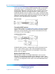
In this case, R4 in Area2 cannot be physically connected to Area0 (for some
reason) and it will be connected to R3 which is NOT a backbone ABR (like
R1 is for instance). As Area2 is not directly connected to backbone Area0 or
directly connected to a backbone ABR router, clients from Area2 will not be
able to access anything outside Area2. Also, router R3 is an ABR router
connected to two non-backbone areas.
In order to solve these problems, virtual-link must be configured between
router R3 and R1 which are both ABRs. Virtual-link cannot be configured
on non-ABR routers.
Consider the following Router IDs:
•
R1 : 1.0.0.0
•
R3 : 3.0.1.0
•
R4 : 4.0.2.0
Virtual-link can be configured in two ways on ABR routers :
•
Configuring virtual link manually
•
Configuring virtual link automatically
The following is an example for creating an auto virtual link:
Creating auto virtual link
R1 (config-router)#auto-vlink
Example : 1
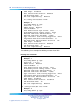
R1(config)#show ip ospf
Router ID: 1.0.0.0
Admin Status: Enabled
Version Number: 2
Area Border Router Oper Status: True
AS Boundary Router Config Status: False
External Link-State Advertisements: 0
External Link-State Checksum: 0(0x0)
Type-of-Service (TOS) Routing Supported: False
Originated Link-State Advertisements: 67
New Link-State Advertisements Received: 722
Nortel Ethernet Routing Switch 5500 Series
Configuration-IP Routing Protocols
NN47200-503 03.01 Standard
5.1 27 August 2007
Copyright © 2005-2007, Nortel Networks
.