
- Nortel Network Multiservice Platform User's Guide

Hardware feature descriptions 3-85
Planning and Ordering Guide—Part 1 of 2 NTRN10AN Rel 12.1 Standard Iss 1 Apr 2004
Note 2: If there is a 29-56 DS1 I/O module installed, and if slots 7 and 8
are not equipped with DS1 mappers, you may not install EC-1x12 circuit
packs in slots 7 and 8 (there is not enough room for slot 7 or slot 8’s BNC
I/O modules).
Note 3: If there is a 29-84 DS1 I/O module installed, and if slots 7 through
10 are not equipped with DS1 mappers, you may not install EC-1x12
circuit packs in slots 7 through 10 (there is not enough room for slot 7
through slot 10’s BNC I/O modules).
Protection switching
EC-1x12 protection switching is 1+1 non-revertive. If a working EC-1x12
circuit pack becomes defective, the traffic is switched to the protection
EC-1x12 circuit pack. Switching can also take place under user control.
Section data communication channel (SDCC)
EC-1x12 circuit packs do not support SDCC channels.
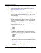
Alarm LED definitions
The following table provides a list of the EC-1x12 circuit pack LEDs. See
Figure 3-28 on page 3-47 for the EC-1x12 circuit pack faceplate layout
showing the location of the LEDs.
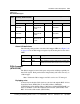
LED Color Description
Status Red Circuit pack failure
Active Green Circuit pack equipment is active and at least one
EC-1 line facility is in service with at least one
cross-connect
LOS (1-12) Yellow Loss of signal on the port