
- Nortel Network Multiservice Platform User's Guide

Hardware feature descriptions 3-93
Planning and Ordering Guide—Part 1 of 2 NTRN10AN Rel 12.1 Standard Iss 1 Apr 2004
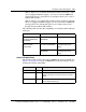
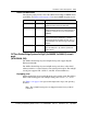
Note 2: If there is a 29-56 DS1 I/O module installed, and if slots 7 and 8
are not equipped with DS1 mappers, you may not install 2x100BT-P2P
circuit packs in slots 7 and 8 (there is not enough room for slot 7 or slot 8’s
8xRJ-45 I/O modules).
Note 3: If there is a 29-84 DS1 I/O module installed, and if slots 7 through
10 are not equipped with DS1 mappers, you may not install 2x100BT-P2P
circuit packs in slots 7 through 10 (there is not enough room for slot 7
through slot 10’s 8xRJ-45 I/O modules).
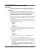
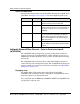
The following table describes the compatibility of each I/O module with both
shelf types.
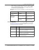
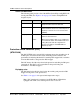
Alarm LED definitions
The following table provides a list of the 2x100BT-P2P circuit pack LEDs. See
Figure 3-28 on page 3-47 for the 2x100BT-P2P circuit pack faceplate layout
showing the location of the LEDs.
Shelf I/O module I/O scenario description
OPTera Metro 3500 Shelf
Assembly (NTN476AA,
NTN476DA)
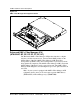
8xRJ-45 Front I/O module
(NTN452NA)
front access to the I/O
OPTera Metro Universal
Shelf Assembly
(NTN476AH)
8xRJ-45 Front Enhanced
I/O module (NTN452NH)
front access to the I/O,
extended temperature
range
8xRJ-45 Rear I/O module
(NTN452HB)
rear access to the I/O,
extended temperature
range
LED name Color Description
Status red Circuit pack failure
Active green The circuit pack is active. At least one Ethernet
facility is in service or at least one cross-connect
exists.
Link (1-2) yellow No link pulse is detected on Ethernet port and the
port is administratively up.