
- Nortel Network Multiservice Platform User's Guide

Operation, administration, and maintenance (OAM) features 2-29
Planning and Ordering Guide—Part 1 of 2 NTRN10AN Rel 12.1 Standard Iss 1 Apr 2004
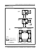
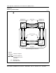
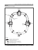
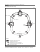
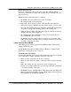
Figure 2-14
STS paths and squelch map for a four-node 2-Fiber BLSR ring
F2247
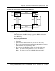
BLSR configurations
The configuration of the BLSR ring is recorded in a BLSR configuration,
which is created on the NPx and then propagated to all the SPx circuit packs
in the BLSR ring.
BLSR configuration attributes
A BLSR configuration contains the following information:
• Ring name
• Optical interfaces involved in the ring (for each node in the ring)
• The associated automatic protection switching (APS) IDs of the involved
optical interfaces (for each node in the ring)
• The adjacent nodes’ APS IDs and TIDs (for each node in the ring)
Note 1: The allowable string characters are "0-9", "A-Z", and "-".
Note 2: The allowable range for an APS ID is between 0 and 15.
Node D
Node A
Node C
Node B
(path a)
Line
STS #3
(path b)
(path c)
(path c)
(path d)
(path b)
(path a)
(path d)
STS #2
STS #3
STS #2
STS #1
STS #2STS #1
Line