R2MFC Media Bay Module Installation and Configuration Guide BCM Business Communications Manager Document Status: Standard Document Number: NN40010-300 Document Version: 03.
Copyright © 2005–2007 Nortel Networks, All Rights Reserved The information in this document is subject to change without notice. The statements, configurations, technical data, and recommendations in this document are believed to be accurate and reliable, but are presented without express or implied warranty. Users must take full responsibility for their applications of any products specified in this document. The information in this document is proprietary to Nortel Networks.
Caution: Only qualified persons should service the system. The installation and service of this hardware is to be performed only by service personnel having appropriate training and experience necessary to be aware of hazards to which they are exposed in performing a task and of measures to minimize the danger to themselves or other persons. Electrical shock hazards from the telecommunication network and AC mains are possible with this equipment.
Hearing Aid Compatibility System telephones are hearing-aid compatible, as defined in Section 68.316 of Part 68 FCC Rules. Repairs In the event of equipment malfunction, all repairs to certified equipment will be performed by an authorized supplier. Changes or modifications not expressly approved by the party responsible for compliance could void the user’s authority to operate the equipment. Important Safety Instructions The following safety instructions cover the installation and use of the Product.
5 Do not place this product on an unstable cart, stand or table. The product may fall, causing serious damage to the product. 6 This product should never be placed near or over a radiator or heat register. This product should not be placed in a built-in installation unless proper ventilation is provided. 7 Do not allow anything to rest on the power cord. Do not locate this product where the cord will be abused by persons walking on it.
Information is subject to change without notice. Nortel Networks reserves the right to make changes in design or components as progress in engineering and manufacturing may warrant. This equipment has been tested and found to comply with the European Safety requirements EN 60950 and EMC requirements EN 55022 (Class A) and EN 55024. These EMC limits are designed to provide reasonable protection against harmful interference when the equipment is operated in a commercial and light industrial environment.
Contents North American Regulatory Information . . . . . . . . . . . . . . . . . . . . . . . . . . . . . . . . . . . . 2 Safety . . . . . . . . . . . . . . . . . . . . . . . . . . . . . . . . . . . . . . . . . . . . . . . . . . . . . . . . . . . 2 Enhanced 911 Configuration . . . . . . . . . . . . . . . . . . . . . . . . . . . . . . . . . . . . . . . . . 3 Radio-frequency Interference . . . . . . . . . . . . . . . . . . . . . . . . . . . . . . . . . . . . . . . . . 3 Hearing Aid Compatibility . . . . . .
Chapter 3 Preparing to install the R2MFC MBM . . . . . . . . . . . . . . . . . . . . . . . . . . . . . . 27 Installation process map . . . . . . . . . . . . . . . . . . . . . . . . . . . . . . . . . . . . . . . . . . . . 28 Host system setup requirements . . . . . . . . . . . . . . . . . . . . . . . . . . . . . . . . . . . . . . 28 R2MFC MBM setup requirements . . . . . . . . . . . . . . . . . . . . . . . . . . . . . . . . . . . . . 29 Config DIP switches . . . . . . . . . . . . . . . . . . . . . . . . .
Configuring the MFCR2 (external) link . . . . . . . . . . . . . . . . . . . . . . . . . . . . . . . . . . . . 49 Setting Config DIP switches . . . . . . . . . . . . . . . . . . . . . . . . . . . . . . . . . . . . . . . . . 49 Creating a customized country code . . . . . . . . . . . . . . . . . . . . . . . . . . . . . . . . . . . 50 PRI side (Internal Link) configurable parameters . . . . . . . . . . . . . . . . . . . . . . . . . . . . 51 E1 Framing . . . . . . . . . . . . . . . . . . . . . . . . . . . . .
R2 directory . . . . . . . . . . . . . . . . . . . . . . . . . . . . . . . . . . . . . . . . . . . . . . . . . . . . . . 87 PRI directory . . . . . . . . . . . . . . . . . . . . . . . . . . . . . . . . . . . . . . . . . . . . . . . . . . . . . 89 Appendix A Configuring DIP switch settings and definitions . . . . . . . . . . . . . . . . . . . . 91 Country code defaults . . . . . . . . . . . . . . . . . . . . . . . . . . . . . . . . . . . . . . . . . . . . . . . . . 93 Mexico Config 1 . . . . . . . . . .
MFC Register Signaling . . . . . . . . . . . . . . . . . . . . . . . . . . . . . . . . . . . . . . . . 106 Panama Config 1 . . . . . . . . . . . . . . . . . . . . . . . . . . . . . . . . . . . . . . . . . . . . . . . . 107 Appendix B Diagnostic and loopback DIP switch settings. . . . . . . . . . . . . . . . . . . . . . 109 Appendix C MFC Signal Definitions . . . . . . . . . . . . . . . . . . . . . . . . . . . . . . . . . . . . . . . . 111 Appendix D CLI Cable Pinout . . . . . . . . . . . . . . . . . . .
NN40010-300
How to Get Help This section explains how to get help for Nortel products and services. Getting Help from the Nortel Web site The best way to get technical support for Nortel products is from the Nortel Technical Support Web site: http://www.nortel.com/support This site provides quick access to software, documentation, bulletins, and tools to address issues with Nortel products.
How to Get Help NN40010-300
Chapter 1 Getting started About this guide This guide explains how to install, configure, and maintain the Nortel R2MFC Media Bay Module (R2MFC MBM). The guide also provides information about the Command Line Interface (CLI) tool used to configure, operate, administer and maintain the R2MFC MBM from a computer. Note: The CLI is separate from the Business Communications Manager (BCM) system configuration tool.
Chapter 1 Getting started Before you begin This guide assumes the following: • • • • The host system is installed and initialized and is working correctly. The host system is running BCM 2.5 FP 1, or greater. Users have a working knowledge of the host system operations. All configuration installers have a working knowledge of the Windows operating system and graphical user interfaces. Acronyms The following is a list of acronyms used in this guide.
Chapter 1 Getting started 17 Table 1 Acronyms (Continued) Acronym Description OOM Out of CRC-4 Multiframe Alignment OOS Out Of Service PCM Pulse Code Modulation PRI Primary Rate Interface RAI Remote Alarm Indication Symbols and text conventions These symbols are used to Highlight critical information for the R2MFC MBM system: Caution: Alerts you to conditions where you can damage the equipment. Danger: Alerts you to conditions where you can get an electrical shock.
Chapter 1 Getting started ! Security note: Indicates a point of system security where a default should be changed, or where the administrator needs to make a decision about the level of security required for the system. Warning: Alerts you to ground yourself with an antistatic grounding strap before performing the maintenance procedure. Warning: Alerts you to remove the R2MFC MBM main unit and expansion unit power cords from the ac outlet before performing any maintenance procedure.
Chapter 1 Getting started 19 Related publications This section provides a list of additional documents referred to in this guide.
Chapter 1 Getting started NN40010-300
Chapter 2 Overview This chapter provides an overview of the R2MFC Media Bay Module (R2MFC MBM). This chapter includes the following information: • • • • “General information” “Administration and maintenance tools” on page 22 “R2MFC MBM faceplate elements” on page 22 “R2MFC MBM back and underside elements” on page 24 General information The R2MFC MBM is a media bay module (MBM) that provides MFC-R2 connectivity over an E1 trunk.
Chapter 2 Overview Administration and maintenance tools R2MFC MBM configuration involves the following: • • Internal link configuration for the PRI internal link to the BCM. The internal link uses preset characteristics and therefore does not require localization. External link configuration of the MFC-R2 E1 the external interface to public network. The external link allows for localization in different countries.
Chapter 2 Overview 23 System Status LEDs The R2MFC MBM has three visual status monitor indicators on the left side of the faceplate. They are: • • • Power LED — This green LED indicates the status of power to the R2MFC MBM. In Service LED — This green LED indicates the status of the E1 signal coming to the R2MFC MBM from the BCM. Diag LED — This red LED indicates if the R2MFC MBM is in a diagnostic or loopback mode. Config DIP switches The R2MFC MBM has six config DIP switches on its faceplate.
Chapter 2 Overview RS232 port There is an RJ-45 serial port connector named RS232 on the faceplate of the R2MFC MBM. The N0026100 cable, shipped with the R2MFC MBM, is used to connect a computer to the RS232 port for advanced configuration or for CLI-based diagnostics of the R2MFC MBM. Appendix D, “CLI Cable Pinout,” on page 113 shows the pinout information to make a new N0026100 cable. E1 Status LEDs The R2MFC MBM has four visual status monitor indicators in the middle section of the faceplate.
Chapter 2 Overview 25 Power connectors The R2MFC MBM receives its power from the BCM chassis through a power connector on the back of the module. Figure 4 shows the placement of the power connectors. Figure 4 R2MFC MBM back DS256 and power connector MBM DIP switches There are DIP switches located on the underside of the R2MFC MBM. These DIP switches are used to select the DS30 buses from the DS256 bus. These DIP switches must be set before the R2MFC MBM is installed.
Chapter 2 Overview NN40010-300
Chapter 3 Preparing to install the R2MFC MBM This chapter provides an overview of the preparation required to install the R2MFC MBM in a host system. (The host system is the BCM system to which the R2MFC MBM connects.) The information in this chapter is based on the following assumptions: • The host system is installed, initialized, and tested. • The installer has a working knowledge of the host system and an understanding of telecommunications.
Chapter 3 Preparing to install the R2MFC MBM Installation process map Figure 6 provides an overview of the R2MFC MBM installation preparation.
Chapter 3 Preparing to install the R2MFC MBM 29 R2MFC MBM setup requirements This section provides the following information about the setup requirements for the R2MFC MBM: • “Config DIP switches” • “MBM DIP switches” • “Environment checklist” • “Software requirements” on page 30 • “Electrical requirements” on page 30 Config DIP switches Determine and set the Config DIP switches to the correct country code, and second dial tone setting for the R2MFC MBM.
Chapter 3 Preparing to install the R2MFC MBM Environment checklist The R2MFC MBM environmental requirements are covered by the host system environment setup. See the BCM Installation and Maintenance guide supplied with the host system for details of environmental requirements. Electrical requirements The R2MFC MBM power is supplied through the chassis on the host sytem. See the BCM Installation and Maintenance guide supplied with the host system for details of the electrical requirements.
Chapter 4 Installing the R2MFC MBM This chapters describes how to install and remove an R2MFC MBM in a host BCM system. This chapter provides the following installation and removal procedures: • • • • “Shutting down the system” “Installing an R2MFC MBM” on page 34 “Removing an R2MFC MBM” on page 38 “Wiring an R2MFC MBM” on page 41 Figure 7 provides an overview of the steps for installing the R2MFC MBM.
Chapter 4 Installing the R2MFC MBM Shutting down the system Before you shut down the system or perform any maintenance procedures, read the following warnings to ensure you and your system are properly protected. Warning: If you are installing a new BCM or an expansion unit, refer to the Installation and Maintenance guide for the host system for instructions about installing a new system before you connect the system to the AC power outlet.
Chapter 4 Installing the R2MFC MBM 33 c Click Ok. The progress update dialog box appears and the BCM system begins the shutdown process. When the shutdown process is complete, the final warning dialog box appears, and the LEDs enter the flashing state. d Click Ok to disconnect Element Manager. When the shutdown Element Manager is disconnected, the system gives an audible beep. The LEDs remain in the flashing state until the hardware is shutdown (see “Shutting down the BCM 4.
Chapter 4 Installing the R2MFC MBM e Wait until the Status changes to Complete! It is safe to turn off the system. f Click Done. g Exit the Unified Manager. 2 Attach one end of the grounding strap to your wrist and the other end to a grounded metal surface. 3 Ensure the cables connected to the front of the BCM and the expansion unit are clearly marked as to how they are connected. 4 Disconnect the BCM and expansion unit power cords from the AC outlet.
Chapter 4 Installing the R2MFC MBM 35 Installing an R2MFC MBM in the expansion unit Perform the following steps to install an R2MFC MBM in the BCM expansion unit chassis. Install the R2MFC MBM when the system is powered down: Caution: Only install the R2MFC MBM when the system is powered down. See “Shutting down the system” on page 32. Warning: Failure to follow procedures to properly disconnect the BCM and expansion unit can result in module or system damage.
Chapter 4 Installing the R2MFC MBM Installing an R2MFC MBM in the BCM50 expansion unit Perform the following steps to install an R2MFC MBM in the BCM50 expansion unit chassis. Install the R2MFC MBM when the system is powered down: Caution: Only install the R2MFC MBM when the system is powered down. See “Shutting down the system” on page 32. Warning: Failure to follow procedures to properly disconnect the BCM and expansion unit can result in module or system damage.
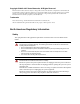
Chapter 4 Installing the R2MFC MBM 37 1 Slide the rubber boot onto the R2MFC transmit co-axial cable. See Figure 8 on page 37. Figure 8 Sliding the rubber boot on to the R2MFC transmit co-axial cable Note: Rubber boots ensure that no ESD occurs on to the co-axial connectors. 2 Connect the R2MFC co-axial cable to the correct location on the MBM. See Figure 9 on page 37.
Chapter 4 Installing the R2MFC MBM Reconnecting the equipment After you install the module correctly into the bay, you must return the equipment to operation. Caution: Complete the following steps carefully to ensure you return your system to operation without endangering the equipment or yourself. 1 Plug the power cords for the BCM and any expansion units back into the AC outlets. Note: The Business Communications Manager system starts up when you connect the AC power cord.
Chapter 4 Installing the R2MFC MBM 39 Removing an R2MFC MBM from the BCM platform base chassis Perform the following steps to remove an R2MFC MBM from the BCM platform base chassis. Remove the R2MFC MBMs after the system is powered down. 1 Power-down the BCM system (see “Shutting down the system” on page 32). 2 Remove any cabling from the R2MFC MBM faceplate. 3 Grasp the right edge of the MBM ejector lever with your thumb, index, and middle fingers. Pull outward to partially eject the R2MFC MBM.
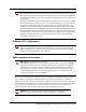
Chapter 4 Installing the R2MFC MBM Figure 12 How to remove a BCM400 R2MFC MBM Grasp the edge of the R2MFC MBM ejector lever Removing an R2MFC MBM from the expansion unit Use this procedure to remove an R2MFC MBM from the BCM expansion unit. Warning: Remove the R2MFC MBM after the system is powered down. 1 Power-down the BCM expansion unit system (see “Shutting down the system” on page 32). 2 Remove any cabling from the R2MFC MBM faceplate. 3 Remove the expansion unit front bezel.
Chapter 4 Installing the R2MFC MBM 41 Figure 13 How to remove the expansion unit front bezel BCM expansion unit 1. Push against the bottom 2. Pull out from the top MBM latches 5 Grasp the top and bottom edges of the R2MFC MBM. Remove the R2MFC MBM from the BCM expansion unit. Place the R2MFC MBM in a clean, safe, and static-free area. Wiring an R2MFC MBM This section describes how to wire the cables that connect to the R2MFC MBM. The R2MFC MBM is connected to the CO by either RJ48C or BNC connectors.
Chapter 4 Installing the R2MFC MBM Warning: Only allow qualified persons to service the BCM system. The installation and service of this unit must be performed by service personnel with the appropriate training and experience. Service personnel must be aware of the hazards of working with telephony equipment and wiring. They must have experience in techniques that minimize any danger of shock or equipment damage.
Chapter 4 Installing the R2MFC MBM 43 Figure 15 Trunk wiring overview Install R2MCF MBM Read warnings Connect cables to appropriate trunk modules Determine the correct connector to use Continue with setup procedures Connecting an R2MFC MBM to a service provider Warning: Electrical shock warning. The Business Communications Manager R2MFC MBMs have been safety-approved for installation into BCM base units and expansion units.
Chapter 4 Installing the R2MFC MBM 3 Attach the transmit BNC cable to the connector labeled Tx and the receive BNC cable to the connector labeled Rx, for countries using BNC connections. Insert the connector into the RJ48 jack on the module, for countries using the RJ48 connections. Figure 14 on page 41 shows the wiring pinouts for an R2MFC MBM to connect to a service provider using RJ48 connectors.
Chapter 5 Configuring the R2MFC MBM Trunk protocol conversion provides interworking between two different trunk protocols, and requires configuration for the following: • • E1- MFCR2 E1- ETSI Euro-PRI The MFCR2 is the external interface. The external interface connects to a public network. The R2MFC MBM contains preprogrammed country-specific MFCR2 settings that can be selected using the DIP switches on the faceplate of the R2MFC MBM. The MFCR2 settings can also be customized.
Chapter 5 Configuring the R2MFC MBM MFCR2 side (External Link) configurable parameters Physical line characteristics The MBM has two options for physical connections on the faceplate: 1 RJ-48 connector for twisted pair cable (line impedance of 120 Ohms) 2 a pair of BNC connectors for coax cables (line impedance of 75 Ohms) The BNC connectors can have one of the following: • • TX shielding connected to ground (default) RX and TX shielding not connected to ground Only one of the two connector types
Chapter 5 Configuring the R2MFC MBM 47 Line signaling Line signaling (for example, seize, answer, and disconnect) are implemented by R2 Channel Associated Signaling known as ABCD bits. Only the two bits AB are used for line signaling. The state (value) of the bits indicate the signal. The channels are always bidirectional, (that is, they accept incoming calls or originate outgoing calls). The channel behavior also supports one-way trunks. The direction of the signal does not need to be configured.
Chapter 5 Configuring the R2MFC MBM End of dialing (incoming) End of dialing for an incoming call can be configured by using the CLI. See Table 3, for the end of dialing options. Table 3 Minimum (or fixed) number length + timer parameters Option Parameters Meaning Default Explicit ‘End of dial’ signal (I-15) None Yes The preset option for all countries.
Chapter 5 Configuring the R2MFC MBM 49 Default category The MFC subscriber category, sent by R2MFC MBM in outgoing calls, is fixed. The default category for all countries is II1 (subscriber without priority). If needed, the default can be changed by CLI. Default subscriber status The user can set default subscriber status (for example, free, busy, and vacant number) for incoming calls.
Chapter 5 Configuring the R2MFC MBM 2 Set the Config DIP switches to the appropriate country code and second dial tone setting that coincides with your location. See Appendix A, “Configuring DIP switch settings and definitions,” on page 91 for predefined country code DIP switch settings and their specifications. See “Turning on second dial tone” on page 58 for the procedure to turn on second dial tone.
Chapter 5 Configuring the R2MFC MBM 3 51 Make the required modifications by CLI. See Chapter 7, “Command Line Interface (CLI),” on page 73 for an explanation of how to access and navigate the CLI. • Configuration changes made through the CLI immediately affect the operating parameters in RAM. • Use the SaveCfg - (save configuration permanently on flash) command to save the new settings on non-volatile Flash memory.
Chapter 5 Configuring the R2MFC MBM Signaling The list of layer 2 signaling parameters are listed in Table 5. Table 5 Layer 2 signaling parameters Parameter Operational Value D-channel LAP D Window size 7 Modulo 128 Layer 3 signaling parameters are listed in Table 6. Table 6 Layer 3 signaling parameters Parameter Operational Value Protocol ETSI Euro-ISDN (ETS 300 102). The R2MFC MBM upper board is the NETWORK side, so the BCM must be configured as USER side.
Chapter 5 Configuring the R2MFC MBM 3 53 Select the appropriate Bus # under Configuration > Resources > Telephony Resources in the navigation tree. The Bus # information frame displays. See Figure 19 for an example of the screen layout for an R2MFC MBM configured on Bus 2.0. Figure 19 BCM Bus configuration for R2MFC MBM 4 Configure the fields in the Details for Module: 2.0 panel. See Table 7 for parameters and settings.
Chapter 5 Configuring the R2MFC MBM 5 Select all active B-channels that are provisioned for the corresponding E1 in Configuration > Resources > Telephony Resources > Provisioned Lines. See Figure 20. There should be 30 channels, unless a partial E1 service is arranged with the CO. See Figure 20, for an example of the screen layout for an R2MFC MBM configured on Bus 2.0.
Chapter 5 Configuring the R2MFC MBM 55 Figure 21 BCM Bus configuration for R2MFC MBM 6 Select Modules on bus > Module 1 from the navigation tree. The Bus # - Module # Information frame displays. See Figure 22 on page 56. 7 Configure the parameters in the Bus# - Module # information frame. See Table 8 for parameters and settings. See Figure 22 on page 56 for an example of the screen layout for an R2MFC MBM configured on Bus 06.
Chapter 5 Configuring the R2MFC MBM Figure 22 BCM module configuration for R2MFC MBM 8 Select Modules on bus > Module 1 > E1 parameters from the navigation tree. The Bus # - Module # - E1 parameters information frame displays. See Figure 23 on page 57. 9 Select Off from the CRC4 drop-down list. See Figure 23 on page 57 for an example of the screen layout for an R2MFC MBM configured on Bus 06.
Chapter 5 Configuring the R2MFC MBM 57 Figure 23 BCM E1 parameters configuration for R2MFC MBM Off 10 Select Modules on bus > Module 1 > Provision lines from the navigation tree. See Figure 24 on page 58. The Bus # - Module # - E1 parameters Information frame displays. 11 Select an individual line that is displayed under the Provision lines heading. See Figure 24 on page 58. The Bus # - Module # - Line # information frame displays. 12 Select Provisioned from the Status drop-down list.
Chapter 5 Configuring the R2MFC MBM Figure 24 BCM lines configuration for R2MFC MBM Turning on second dial tone Second dial tone, when turned on, generates and supplies, a second dial tone to the end user, after the end user dials the trunk access code. Second dial tone can be used with any country code, including customized country codes. You must turn on second dial tone at the BCM level when running a BCM 4.0 device, or you must turn on second dial tone at the R2MFC MBM level when running a BCM 3.
Chapter 5 Configuring the R2MFC MBM 59 Figure 25 Outgoing dialing configuration for second dial tone Turning on second dial tone using Unified Manager Config DIP switch 6 is designated for turning on or off second dial tone. Changes to the dial tone DIP switch become effective, as soon as the DIP switch changes position, and does not require a restart to take effect. The BCM outgoing dialing must be set to Overlap in order for second dial tone to work properly.
Chapter 5 Configuring the R2MFC MBM The routes configured on the BCM are listed below the Routes heading. 6 Select the route that is to be configured under the Routes heading. See Figure 26 on page 60. The Route # information frame displays. 7 Select Overlap from the Service type drop-down list. 8 Repeat Steps 6 and 7 for every active B-channel that is provisioned for the corresponding E1. There will be 30 channels, unless a partial E1 service is arranged with the CO.
Chapter 6 R2MFC MBM maintenance This chapter describes the general maintenance of the R2MFC MBM after it is installed and is running properly.
Chapter 6 R2MFC MBM maintenance During call setup, the following information is passed between the BCM and the CO: 1 Dialed digits — Dialed digits are passed without any change. Up to 24 digits can be dialed. The MFC trunk is capable of repeating dialed digits on outgoing calls to the CO, when requested according to protocol. Digits are passed immediately to BCM as they are received (PRI overlap mode) on incoming calls from CO to BCM.
Chapter 6 R2MFC MBM maintenance 63 Diagnostic tools The R2MFC MBM has three diagnostic settings and two loopback settings available to help with the troubleshooting process. When the R2MFC MBM is running in diagnostic or loopback mode, the signals from the BCM to the CO, or from the CO to the BCM, can be intercepted by placing diagnostic equipment in the bantam jacks on the front of the R2MFC MBM. This allows the external MFCR2 link, or the internal E1, to be checked for communication errors.
Chapter 6 R2MFC MBM maintenance Alarms Performance is monitored on both the internal (PRI) and external (MFC) links, but the actions when errors occur are different. Alarms and events handling include three types of actions: 1 Propagating Alarms: a Alerts the far-end by transmitting remote alarm indication (RAI). b Passes alarm conditions from link to link.
Chapter 6 R2MFC MBM maintenance 65 Group II errors Group II alarms occur when an alarm persists for a predefined period. The alarm is considered cleared when it does not occurred for a predefined period. See Table 11 for incoming-signal Group II errors listed from highest to lowest priority. Group II errors are ordered by priority; when a high priority error exists, any errors of lower priority are irrelevant.
Chapter 6 R2MFC MBM maintenance Table 12 Group I Alarms propagation (Sheet 2 of 2) Error Condition Alarm Transmitted to far end Alarm sent on opposite link CRC-4 errors RAI AIS FEBE none none Table 13 shows the reactions for Group II alarms when they persist.
Chapter 6 R2MFC MBM maintenance 67 The second set of LEDs on the faceplate indicate the operation status for the E1. Table 15 describes the LEDs and what status they indicate. Table 15 System status monitor LEDs LED Name Yellow LED OFF Red LED ALM Rx Problem with digital input on external R2 link; link unusable. Normal Operation N/A ERR Tx Remote Alarm Indication (RIA) transmitted on external R2 link.
Chapter 6 R2MFC MBM maintenance Replacing an R2MFC MBM When an R2MFC MBM requires replacement, follow the steps in this section. Warning: This section describes replacing a module with the same type of module. If you want to replace a module with a different type of module, you must treat it as a new installation. Refer to the Installation and Maintenance guide to ensure the new module does not overrun any lines already assigned to other modules.
Chapter 6 R2MFC MBM maintenance 69 6 Record the switch settings from the old module. 7 Set the DIP switches on the new module to match the settings you recorded in the previous step. 8 Refer to “Installing an R2MFC MBM” on page 34 to install the module in the media bay. 9 Refer to “Repeat steps 1 and 2 to attach the rubber boot to the other R2MFC co-axial cable.” on page 37 to restore the system to operation. Upgrading firmware Normal installation does not require firmware download.
Chapter 6 R2MFC MBM maintenance Figure 28 Upgrading firmware overview Firmware Upgrade Required Is f irmware corrupted? Y es No Copy the firmware load and PC program files to PC Prepare R2FMC MBM for upload Disconnect PC from R2FMC MBM Connect PC to the R2FMC MBM Upload new firmware file Check the module to see if it is working properly Open a Hyper-terminal session to connect to R2FMC MBM Verify the version of new firmware Disable links Perform the following steps to download the firmware
Chapter 6 R2MFC MBM maintenance 71 6 Go to step 8 if the BCM is not active and no calls are running. If calls are running, access the Control directory. 7 Execute the soft disable (LSD), or immediate disable (LID), to disable the links. 8 Enter the load subdirectory. 9 Execute load y command. 10 Wait for the output of the boot monitor. 11 Enter fload to prepare the MBM for the uploading of firmware. The R2MFC MBM will not respond while it is waiting for a download.
Chapter 6 R2MFC MBM maintenance NN40010-300
Chapter 7 Command Line Interface (CLI) Overview This chapter describes the Command Line Interface (CLI) available through the serial port. Command Line Interface (CLI) commands are organized as a tree of directories. Each directory contains a set of commands related to a specific purpose or subject.
Chapter 7 Command Line Interface (CLI) Accessing the CLI The CLI is accessed through the RS-232 port on the faceplate of the R2MFC MBM. The cable that was shipped with the R2MFC MBM, part number N0026100, is used to connect a computer to the R2MFC MBM. Perform the following steps to access the CLI: 1 Use the shipped cable to connect a PC to the RS-232 port on the faceplate of the R2MFC MBM through COM1.
Chapter 7 Command Line Interface (CLI) 75 Commands The following section lists and describes the CLI commands for the available directories. LOad directory Table 18 includes the CLI commands for firmware download and card restart. The commands are accessed from the LOad directory. Table 18 LOad directory CLI commands CLI command Description RST Restarts card firmware regardless of current state. There is no prompt to confirm the restart.
Chapter 7 Command Line Interface (CLI) VIew directory Table 20 includes the CLI commands to display the setup parameters. The commands are accessed from the VIew directory. Table 20 VIew directory CLI commands CLI command Description LNst Displays the status of both links. ChSt Displays the status of the channels in the given range. Where: chan1 is the lower limit of the range. chan2 is the upper limit of the range. The values for chan1 and chan2 are 1...15, 17...31.
Chapter 7 Command Line Interface (CLI) 77 CNtrl directory Table 21 includes the CLI commands for maintenance functions. The commands are accessed from the CNtrl directory. All enable and disable commands are to be used for troubleshooting purposes only. For normal operation, both links and all channels must be enabled (default state). This includes links and channels in an environment with a partial E1 arrangement. Warning: Channels are not available to process calls when a link is disabled.
Chapter 7 Command Line Interface (CLI) Table 21 CNtrl directory CLI commands (Sheet 2 of 3) CLI command Description CEnbl Performs channel enabling. Where: chan is the channel number in the range of 1...15, 17...31. This command sends a message to both protocol handlers. CEnblGrp Performs channel enabling on a group of channels. Where: start_chan is the first channel in the group. end_chan is the last channel in the group. The values for start_chan and end_chan are 1..
Chapter 7 Command Line Interface (CLI) 79 Table 21 CNtrl directory CLI commands (Sheet 3 of 3) CLI command Description CoNlm Transfers the channel to an online state. Where: chan is the channel number in the range of 1...15, 17...31. If the system accepts the message, the channel becomes disabled. This command sends a message to both protocol handlers. CoNlmGrp Transfers a group of channels to an online state. Where: start_chan is the first channel in the group.
Chapter 7 Command Line Interface (CLI) Table 22 COnfig directory CLI commands (Sheet 2 of 2) CLI command Description EraseCfg Erases the configuration from non-volatile Flash memory. As a result, the custom profile does not exist, and other parameters are not included in custom profile use factory default settings. A live system is not affected, because current configuration is stored in RAM. The R2MFC MBM tries to read configuration from Flash memory on restart.
Chapter 7 Command Line Interface (CLI) 81 ALarm directory Table 23 includes the CLI commands for alarm configuration and status. The commands are accessed from the ALarm directory. Table 23 ALarm directory CLI commands (Sheet 1 of 2) CLI command Description G1Res Resets Group 1 alarm counters. Where: link_no is the link number, either 0 or 1.
Chapter 7 Command Line Interface (CLI) Table 23 ALarm directory CLI commands (Sheet 2 of 2) CLI command Description GRDtime Changes group 1 alarm guard time for the required grade of service state. Where: link_no is the PCM link number, 0 or 1. grs_state is the grade of service state, 1 (mnt state) or 2 (oos state). grd_time is the guard time in the range of 20...50000.
Chapter 7 Command Line Interface (CLI) 83 SWerr directory Table 24 includes the CLI commands for the Software Error (SWerr) utility. The firmware stores the Swerr messages into a cyclic buffer. The contents of the buffer are printed upon request.The commands are accessed from the SWerr directory. Table 24 SWerr directory CLI commands CLI command Description PS Prints the Swerr buffer constants. All the accumulated swerr messages are printed.
Chapter 7 Command Line Interface (CLI) MFC directory Table 25 includes the CLI commands for the configuration and control of MFC-R2 protocols. The commands are accessed from the MFC directory. Table 25 MFC directory CLI commands (Sheet 1 of 3) CLI command Description ICm Sets and displays incoming call timers. Where: mfc_link is the number of required mfc/r2 links. incoming_timer_type is one of the timers defined for incoming mfc call processing.
Chapter 7 Command Line Interface (CLI) 85 Table 25 MFC directory CLI commands (Sheet 2 of 3) CLI command Description CatgOpt Defines which MFC category to transmit in outgoing calls. Where: mfc_link is the number of the link, 0 or 1. flag defines the MFC category (default is 0). DefltCatgVal Defines the MFC category value when CatgOpt is set to the default value. Where: mfc_link is the number of the link, 0 or 1. category is the MFC category in the range of 1...
Chapter 7 Command Line Interface (CLI) Table 25 MFC directory CLI commands (Sheet 3 of 3) CLI command Description EndAniType Defines how to determine end of ANI digits. Where: mfc_link is the number of the link, 0 or 1. direction is 0 (IC), 1 (OG), or 2 (both). type is either 0 (Ix signal) or 1 (fixed number of digits). SetAniCount Defines the number of expected ANI digits when EndAniType is set to a fixed number of digits.
Chapter 7 Command Line Interface (CLI) 87 R2 directory Table 26 includes the CLI commands for R2 line signaling. The commands are accessed from the R2 directory. Table 26 R2 directory CLI commands (Sheet 1 of 2) CLI command Description RS Sets the R2 signaling values. Where: link is the number of the link, 0 or 1. line_signal_meaning is one of the line signal meaning codes. R2_signal is the ABCD bits value of 0, 1, 2, or 3.
Chapter 7 Command Line Interface (CLI) Table 26 R2 directory CLI commands (Sheet 2 of 2) CLI command Description SeizeOption Sets seize interworking with opposite link upon detecting seize from far end. Where: link is the number of the link, 0 or 1. flag is either 0 (seize process is autonomic) or 1 (seize process is dependant). Autonomic - link responds to seize without waiting for opposite link ack. Dependant - link waits for opposite link ack before sending its ack.
Chapter 7 Command Line Interface (CLI) 89 PRI directory Table 27 includes the CLI commands for the PRI directory. The commands are accessed from the PRI directory. Table 27 PRI directory CLI commands CLI command Description UNS Displays the user and network side information. For R2MFC MBM the value is hard-coded as network side. SDT Sets the dial type to overlap or non-overlap. Where: dial_type is either 0 (enblock/non-overlap) or 1 (overlap). The default is non-overlap.
Chapter 7 Command Line Interface (CLI) NN40010-300
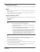
Appendix A Configuring DIP switch settings and definitions This appendix shows the faceplate DIP switch settings for the country codes and for second dial tone. It also contains the definitions of the settings for the different countries codes. See Figure 30 on page 92 for country code DIP switch settings and Figure 31 on page 92 for second dial tone DIP switch settings. Figure 29 shows the Config DIP switch layout.
Configuring DIP switch settings and definitions Figure 30 Country selection DIP switch settings 6 5 4 3 2 1 6 5 4 3 2 1 Mexico 1 6 5 4 3 2 Mexico 2 6 1 5 4 3 2 1 Peru Argentina 6 5 4 3 2 1 6 5 4 3 2 1 Brazil 1 6 5 4 3 2 Brazil 2 6 1 5 4 3 2 1 Unassigned 6 5 4 3 2 1 Unassigned 6 5 4 3 2 1 Unassigned 6 5 4 3 2 Unassigned 6 1 5 4 3 2 1 Unassigned 6 5 4 3 2 1 Unassigned 6 5 4 3 2 1 Unassigned 6 5 4 3 2 Chile 6 1 5
Configuring DIP switch settings and definitions 93 Country code defaults This section contains the default configuration associated to the country code set by the DIP switches on the faceplate of the R2MFC MBM.
Configuring DIP switch settings and definitions MFC register signaling MFC signal definitions depends on the stage and the direction of the call; there are four tables of 15 signals each: the first stage uses I signals forward and A signals backward, and the second stage uses II signals forward and B signals backward. The meaning of the signals can also be different when being transmitted or received. Meanings of the MFC signals are configurable.
Configuring DIP switch settings and definitions 95 Table 30 Interpretation of transmitted MFC signals (Sheet 2 of 2) Meaning Signal Meaning Signal Meaning Signal BW_OrigDn A_1 FW_Digit_7 I_7 FW_Categ_9 II_9 BW_FreeCharge B_1 FW_Digit_8 I_8 FW_Categ_10 II_10 BW_FreeNoChrg B_5 FW_Digit_9 I_9 FW_Categ_11 II_11 BW_CntrCharge B_1 FW_Digit_0 I_10 FW_Categ_12 II_12 BW_Busy B_2 FW_Digit_11 I_11 FW_Categ_13 II_13 BW_Unlocated B_4 FW_Digit_12 I_12 FW_Categ_14 II_14 BW_OutOf
Configuring DIP switch settings and definitions R2 line signaling Mexico Config 2 R2 signals are according to CCITT standard. See Table 31 for the Mexico Config 2 R2 signal definitions. Table 31 Mexico Config 2 R2 A/B signals Forward Signal Backward A B Idle 1 0 Seize 0 Clear forward 1 Signal A B Idle 1 0 0 Seize acknowledge 1 1 0 Answer 0 1 Clear back 1 1 Block 1 1 Note: CD bits are not used. They are set to 01 in transmit direction, and are ignored in receive direction.
Configuring DIP switch settings and definitions 97 Table 32 Interpretation of received MFC signals (Sheet 2 of 2) Meaning Signal Meaning Signal Meaning Signal Meaning Signal FW_Digit_8 I_8 FW_Categ_8 II_8 BW_Prev3Digit A_8 BW_OutOfOrder B_8 FW_Digit_9 I_9 FW_Categ_9 II_9 BW_OrigDn A_9 BW_B_Congest B_9 FW_Digit_0 I_10 FW_Categ_10 II_10 BW_ReSend A_10 BW_B_Congest B_10 FW_Digit_11 I_11 FW_Categ_11 II_11 BW_NextDig A_11 BW_B_Congest B_11 FW_ReqFault I_12 FW_Categ_12
Configuring DIP switch settings and definitions Brazil Config 1 E1 physical characteristics • • Connector type: BNC Line coding: HDB3 E1 framing Frame mode: Alternate Register signaling • • • Regret option: ON End of dialing (Incoming): 4 End of dialing (Outgoing): 4 R2 line signaling Brazil Config 1 R2 signals are according to CCITT standard. See Table 34 for the Brazil Config 1 R2 signal definitions.
Configuring DIP switch settings and definitions 99 Table 35 shows the MFC signal configuration in the R2MFC MBM accessed through the CLI for Brazil Config 1. Table 36 shows the MFC transmitted signal configuration in the R2MFC MBM accessed through the CLI for Brazil Config 1. These values are pre-configured by the faceplate DIP switches as shown in Figure 30 on page 92. See Chapter 7, “Command Line Interface (CLI),” on page 73 for information on the CLI.
Configuring DIP switch settings and definitions Table 36 Interpretation of transmitted MFC signals (Sheet 2 of 2) Meaning Signal Meaning Signal Meaning Signal BW_OutOfOrder B_4 FW_Digit_13 I_13 FW_Categ_15 II_15 BW_ChangOrder B_4 FW_Digit_14 I_14 FW_KD_Local II_3 FW_ReqFault I_12 FW_Digit_15 I_15 FW_KD_LnDst II_2 FW_EndDigits I_15 FW_Categ_1 II_1 Brazil Config 2 E1 physical characteristics • • Connector type: BNC Line coding: HDB3 E1 framing Frame mode: Alternate Registe
Configuring DIP switch settings and definitions 101 R2 line signaling Brazil Config 2 R2 signals are according to CCITT standard. See Table 37 for the Brazil Config 2 R2 signal definitions. Table 37 Brazil Config 2 R2 A/B signals Forward Signal Backward A B Idle 1 0 Seize 0 Clear forward 1 Signal A B Idle 1 0 0 Seize acknowledge 1 1 0 Answer 0 1 Clear back 1 1 Block 1 1 Note: CD bits are not used.
Configuring DIP switch settings and definitions Table 38 Interpretation of received MFC signals (Sheet 2 of 2) Meaning Signal Meaning Signal Meaning Signal Meaning Signal FW_Digit_8 I_8 FW_Categ_8 II_8 BW_Prev3Digit A_8 BW_B_Congest B_8 FW_Digit_9 I_9 FW_Categ_9 II_9 BW_PrevDigit A_9 BW_B_Congest B_9 FW_Digit_0 I_10 FW_Categ_10 II_10 BW_Illegal A_10 BW_B_Congest B_10 FW_Digit_11 I_11 FW_Categ_11 II_11 BW_Illegal A_11 BW_B_Congest B_11 FW_ReqFault I_12 FW_Categ
Configuring DIP switch settings and definitions 103 E1 Framing Frame mode: Alternate Register signaling • • • Regret option: OFF End of dialing (Incoming): terminated by indication from destination switch, or by MFC forward signal FW_EndDigits End of dialing (Outgoing): terminated by indication from destination switch, or by MFC forward signal FW_EndDigits R2 Line Signaling Argentina Config 1 R2 signals are according to CCITT standard.See Table 40 for the Argentina Config 1 R2 signal definitions.
Configuring DIP switch settings and definitions Table 41 shows the MFC received signal configuration in the R2MFC MBM accessed through the CLI for Argentina Config 1. Table 42 shows the MFC transmitted signal configuration in the R2MFC MBM accessed through the CLI for Argentina Config 1. These values are pre-configured by the faceplate DIP switches as shown in Figure 30 on page 92. See Chapter 7, “Command Line Interface (CLI),” on page 73 for information on the CLI.
Configuring DIP switch settings and definitions 105 Table 42 Interpretation of transmitted MFC signals (Sheet 2 of 2) Meaning Signal Meaning Signal Meaning Signal BW_OutOfOrder B_8 FW_Digit_13 I_13 FW_Categ_15 II_15 BW_ChangOrder B_4 FW_Digit_14 I_14 FW_KD_Local II_3 FW_ReqFault I_12 FW_Digit_15 I_15 FW_KD_LnDst II_2 FW_EndDigits I_15 FW_Categ_1 II_1 Chile Config 1 E1 Physical Characteristics • • Connector type: BNC Line coding: HDB3 E1 Framing Frame mode: Alternate Register
Configuring DIP switch settings and definitions Table 43 Chile Config 1 R2 A/B signals Forward Signal Backward A B Signal Block A B 1 1 Note: CD bits are not used. They are set to 01 in transmit direction, and are ignored in receive direction.
Configuring DIP switch settings and definitions 107 Table 45 Interpretation of transmitted MFC signals Meaning Signal Meaning Signal Meaning Signal BW_NextDig A_1 FW_ReqFault I_12 FW_Categ_1 II_1 BW_BCateg A_3 FW_EndDigits I_15 FW_Categ_2 II_2 BW_RtrnToA A_1 FW_EndANIdgts I_15 FW_Categ_3 II_3 BW_A_Congest A_4 FW_Digit_1 I_1 FW_Categ_4 II_4 BW_B_Congest B_4 FW_Digit_2 I_2 FW_Categ_5 II_5 BW_Category A_5 FW_Digit_3 I_3 FW_Categ_6 II_6 BW_SpeechChrg A_6 FW_Digit_4
Configuring DIP switch settings and definitions NN40010-300
Appendix B Diagnostic and loopback DIP switch settings See Figure 32 for diagnostic and loopback DIP switch settings.
Diagnostic and loopback DIP switch settings NN40010-300
Appendix C MFC Signal Definitions See Table 46 for meaning of MFC signals.
MFC Signal Definitions NN40010-300
Appendix D CLI Cable Pinout A special cable is required to connect to the RS232 port for use of the CLI. The cable, part number N0026100, is shipped with the R2MFC MBM. Figure 33 shows the cable pins for this cable if you are required to make a new cable.
CLI Cable Pinout NN40010-300