Part No.
Copyright © 2001 Nortel Networks All rights reserved. July 2001. The information in this document is subject to change without notice. The statements, configurations, technical data, and recommendations in this document are believed to be accurate and reliable, but are presented without express or implied warranty. Users must take full responsibility for their applications of any products specified in this document. The information in this document is proprietary to Nortel Networks Inc.
Caution: Only qualified technicians should install this equipment. Place all printed circuit boards on an antistatic mat until you are ready to install them. If you do not have an antistatic mat, wear a discharge leash to free yourself of static before touching any of the printed circuit boards, or free yourself of static by touching a grounded metal object before handling a printed circuit board. Product Safety Meets requirements of: CSA 22.2 No. 950-M95/UL1950, 3rd ed.
Avvertenza: Le apparecchiature a fibre ottiche emettono raggi laser o infrarossi che possono risultare dannosi per gli occhi. Non guardare mai direttamente le fibre ottiche o le porte di collegamento. Tenere in considerazione il fatto che i cavi a fibre ottiche sono collegati a una sorgente luminosa.
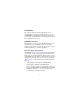
Introduction This section describes how the Nortel Networks* coarse wavelength division multiplexed Gigabit Interface Converter (CWDM GBIC) works within the optical routing system. It also provides a list of CWDM GBICs by wavelength and shows how they are labeled and color-coded. CWDM GBIC description CWDM GBICs are transceivers that link Gigabit Ethernet ports with fiber optic networks.
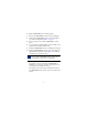
Figure 1 CWDM GBIC 10292FA CWDM GBIC labeling Figure 2 shows how Nortel Networks CWDM GBICs are labeled, including color-coding by wavelength.
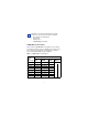
Note: When you contact Nortel Networks about this product, have the following information available: • Nortel Networks serial number • Wavelength • Interface type • CWDM GBIC part number CWDM GBIC model numbers Table 1 lists the CWDM GBIC model numbers by wavelength and matching multiplexers in the CWDM optical routing system. The system uses color matching for simplifying connections between the CWDM GBIC and the multiplexer.
Handling, safety, and environmental guidelines Before installing a CWDM GBIC, read the following handling, safety, and environmental guidelines: • CWDM GBICs are static sensitive. To prevent damage from electrostatic discharge (ESD), follow your normal board and component handling procedures. • CWDM GBICs are dust sensitive. When you store a CWDM GBIC, or when you disconnect it from a fiber optic cable, always keep the dust cover over the CWDM GBIC’s optical bores.
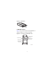
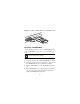
To install a CWDM GBIC in the switching module: 1 Remove the CWDM GBIC from its protective packaging. 2 Verify that the CWDM GBIC is the correct wavelength for your network configuration (Table 1 on page 7). 3 Remove the dust cover from the CWDM GBIC’s optical bores. 4 To prevent damage during handling, clean the ferrules of the optical connector with an alcohol swab. 5 Grasp the CWDM GBIC between your thumb and forefinger.
Figure 3 Inserting a CWDM GBIC into the switching module 9708FA Removing a CWDM GBIC Use the following procedure to remove a CWDM GBIC. When storing a CWDM GBIC, place a dust cover over the fiber optic bores . Note: When disposing of a CWDM GBIC, comply with all national laws and regulations. To remove a CWDM GBIC from the switching module: 1 Disconnect the fiber cable from the CWDM GBIC connector.
CWDM GBIC specifications Table 2 CWDM GBIC specifications Item Specification Physical dimensions 0.39 X 1.18 X 2.56 inches (1 X 3 X 6.5 cm) Connectors single mode fiber optic SC Cabling SMF, 9 µm Data rate Nominal range 1.0625 to 1250 Mbaud Average launch power minimum maximum 0 dBm +4 dBm Transmitter extinction ratio minimum 7 dB Average receive power minimum maximum -24 dBm -1 dBm Power supply maximum 3.15 to 5.
Note: A minimum attenuation of 5 dB must be present between the transmitter and receiver. To avoid receiver saturation, you must insert a minimum attenuation of 5 dB when: • testing the GBIC in loopback mode • using short runs of fiber with no intermediate CWDM OADM or CWDM OMUX To determine the expected signal loss for a CWDM OADM, CWDM OMUX, or fiber length, see Installation and Networking Guidelines for Optical Routing, part number 212257-A. Given a loss budget of 24 dB and assuming fiber loss of .
Acrobat Reader* to open the manuals and release notes, search for the sections you need, and print them on most standard printers. Go to Adobe Systems at the www.adobe.com URL to download a free copy of the Adobe Acrobat Reader. You can purchase selected documentation sets, CDs, and technical publications through the Internet at the www1.fatbrain.com/documentation/nortel/ URL.
An Express Routing Code (ERC) is available for many Nortel Networks products and services. When you use an ERC, your call is routed to a technical support person who specializes in supporting that product or service. To locate an ERC for your product or service, go to the www12.nortelnetworks.com/ URL and click ERC at the bottom of the page.