411-2021-111 Wireless Networks DualMode Metrocell Cell Site Description 411-2021-111 Standard 01.
Wireless Networks DualMode Metrocell Cell Site Description Product release: DualMode Metrocell Document release: Standard 01.01 Date: June 1996 Document Number: 411-2021-111 Copyright Country of printing Confidentiality Legal statements Trademarks 1996 Northern Telecom Printed in the United States of America NORTHERN TELECOM CONFIDENTIAL: The information contained in this document is the property of Northern Telecom.
iv Publication history June 1996 Standard 01.01 Initial release of document. 411-2021-111 Standard 01.
v Contents Publication history iv About this document ix Intended audience for this publication ix How this publication is organized x Applicability of this publication x List of terms xi Introduction 1-1 Northern Telecom's DualMode Metrocell 1-1 The 800 MHz cellular band 1-4 Cell Site Configurations 2-1 Overview 2-1 Omni configuration 2-1 120° sectorized configuration 2-2 60° sectorized configuration 2-4 Cell Site Layouts 3-1 Omni cell site configuration 3-1 Control Channel redundancy 3-2 T
vi Contents Cell Site Components 4-1 Customer Service Operations 4-3 Power and Grounding Requirements 5-1 Safety requirements 5-1 Power and grounding requirements 5-2 Frame power distribution 5-5 System power protection 5-6 Grounding 5-6 Cable Identification 5-9 Datafilling a Metro Cell Site 6-1 Datafill Overview 6-1 Table CLLI 6-2 Table ACUALM 6-2 Table VCHINV, CCHINV, LCRINV 6-5 Appendices Appendix A: DualMode Metrocell Cell Site Specifications 7-1 System Configuration 7-1 Radio Frequency 7-1 A
Contents vii Figure 3-4 Figure 3-5 Figure 3-6 Figure 3-7 Figure 3-8 Figure 3-9 Figure 3-10 Figure 3-11 Figure 5-1 Figure 6-1 Figure 6-2 Frame layout of a 120° STSR Metrocell site with one RF frame (front view) 3-9 Frame layout of a 120° STSR Metrocell site with three RF frames (front view) 3-9 Block diagram of a 120° STSR Metrocell using one RF Frame 3-10 Block diagram of a 120° STSR Metrocell using three RF Frames 311 Frame layout of a 60° STSR Metrocell with two RF frames (front view) 3-22 Typical frame
viii Contents Table 4-1 Table 5-1 Table 5-2 Table 6-1 Table 6-2 Table 6-3 Table 6-4 Table 6-5 Table 6-6 Major components of a DualMode Metrocell 4-1 Metrocell DC Power performance requirements 5-3 Cable identification - North America 5-9 Datafill differences of the Metrocell from an NT800DR cell 6-1 Trunk requirement for different Metrocell configurations 6-2 MTX Datafill Alarm Points for Metro RF Frame 6-3 MTX Alarm Points Datafill Numbers for Metro RF Frame 6-4 MTX Alarm Points Datafill Numbers for Metro
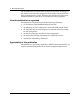
ix About this document This publication is one of a set of documents that provide Northern Telecom (Nortel) customers with information and suggestions on the planning and maintenance of their DualMode Metrocell system.
x About this document The document suite assumes that the reader possesses a basic knowledge of the cellular system and radio propagation and is familiar with measurement units incorporated in the system. Therefore, this document will not provide detailed information on the theory of switching and radio propagation.
xi List of terms A-Band The lower 333 channels (Channel 1 - 333) of the cellular band, normally assigned to a non-wireline operator in the US and Canada. The Expanded Spectrum provides 83 more channels, 50 (Channel 667 - 716) in the A’-Band and 33 (channel 991 - 1023) in the A"-Band. ACU Alarm Control Unit. A unit that provides discrete alarm monitoring, reporting and control functions at the cell site.
xii List of terms Cell By theoretical design, it is the geographical representation of the cellular coverage area or service area defining both the associated size and shape. CSM2 Cell Site Monitor 2. A unit that provides analog testing and monitoring capabilities at the cell site. dBm Decibels above a milliwatt. Unit of power measurement popular in wireless telephony, general telephony, audio, and microwave. dBW Decibels above a watt. Unit of measurement for radio power DCC Digital Color Code.
List of terms xiii FDMA Frequency Division Multiple Access. A frequency assignment arrangement whereby all users share the total frequency allotment and each frequency is assigned to a given user at access on a multiple user access basis. Filter A frequency selective device which is tuned to pass some frequencies and attenuate others. Common filter types include high-pass, low pass, band-pass, and notch filters FM Frequency Modulation.
xiv List of terms Modulation The process of placing information on an RF carrier. The modulation technique may involve changing the amplitude, frequency, or phase of the carrier determined by the modulation index. NES Non-expanded Spectrum. The frequency spectrum initially assigned to the cellular band. The Non-expanded Spectrum provides 333 channels to each of the two bands, the A-Band and the B-Band. Omni An antenna design which permits radiation in essentially all H-Plane azimuths.
List of terms xv RMC Receive Multicoupler. A device for amplifying the input received from a single antenna and providing multiple outputs for a group of receivers. RSSI Received Signal Strength Indicator. A measurement of the received RF signal strength measured at the base station or the subscriber terminal. It is expressed in dBm. SAT Supervisory Audio Tone. A tone of 5970, 6000, or 6030 Hz which modulates the AMPS voice channel along with voice audio.
xvi List of terms ST Signaling Tone. In AMPS cellular, a 10 kHz tone transmitted on the Reverse Voice Channel (RVC) as a precursor to messaging activity, and for certain callprocessing functions (acknowledgments, call termination). Presence of the tone mutes normal conversational audio. STSR Sectored-Transmit/Sectored-Receive. A cell configuration in which a different control and voice frequency assignment is designated for each sector. A directional antenna system is required for each sector.
1-1 1 Introduction Northern Telecom's DualMode Metrocell As cellular systems evolve to the digital format, service providers and mobile subscribers are confronted by a mixture of analog and digital technologies. Northern Telecom (Nortel)’s dual mode cellular product allows a smooth transition from analog to digital technology. It uses Time Division Multiple Access (TDMA) technology for digital systems and Advanced Mobile Phone Service (AMPS) technology for analog systems.
1-2 Introduction Figure 1-1 System architecture of a DualMode Metrocell Trunk PSTN DMS-MTX Digital Transmission Facility DualMode Metrocell Figure 1-2 Digital ready cellular product DMS - MTX DRU voice & control voice and control ICP DRUM control ICRM CSM2 control ACU SWITCH SITE CELL SITE There are at least two equipment frames in a Metrocell, a Universal Common Equipment (CE) Frame and a Metro Radio Frequency (RF) Frame.
Introduction 1-3 Figure 1-3 Basic components of a DualMode Metrocell Universal CE Frame RIP DRUM ACU HSMO CSM2 Dual RMC (one to six) Metro RF Frame RIP Duplexer (one to three) ATC TRU/DPA Shelf (TRUs & DPAs) ATC TRU/DPA Shelf (TRUs & DPAs) ICRM Legend: RIP DRUM ACU HSMO CSM2 RMC ICRM ATC TRU DPA ATC Blank Panel TRU/DPA Shelf (TRUs & DPAs) Base Base Rack Interface Panel DualMode Radio Unit Monitor Alarm Control Unit High Stability Master Oscillator Cell Site Monitor 2 Receive Multicoupler Integrate
1-4 Introduction The 800 MHz cellular band In an 800 MHz North American cellular system, a frequency spectrum of 50 MHz is available for service. Operating from 824 to 894 MHz, including the expanded spectrum, the system conforms to the AMPS IS-54 protocol. Typically this range is divided into 832 radio frequency (RF) channels. The 832 RF channels are divided into two bands,A and B. The two bands are identified as follows: • Band A—for Non-Wireline Operators • Band B—for Wireline Operators.
Introduction 1-5 Table 1-1 Channel designation and frequency assignment System Channel Cell site receive frequency (MHz) Cell site transmit frequency (MHz) Not used 990 824.010 869.010 A" 991 - 1023 824.040 - 825.000 869.040 - 870.000 A 1 - 333 825.030 - 834.990 870.030 - 879.990 B 334 - 666 835.020 - 844.980 880.020 - 889.980 A’ 667 - 716 845.010 - 846.480 890.010 - 891.480 B’ 717 - 799 846.510 - 848.970 891.510 - 893.
1-6 Introduction 411-2021-111 Standard 01.
2-1 2 Cell Site Configurations Overview The DualMode Metrocell can be configured in the following ways: • Omni-directional transmit/receive • 120° Sectored Transmit Sectored Receive (STSR) • 60° Sectored Transmit Sectored Receive (STSR) The majority of systems may begin as Omni-directional to minimize startup costs. As the subscriber traffic increases, the Omni configuration may reach its maximum traffic capacity.
2-2 Cell Site Configurations Figure 2-1 shows the layout of an Omni (N=7) frequency reuse plan;. The RF channels used in Cell 1 of a cluster are reused in Cell 1 of other clusters, channels in Cell 2 are reused in Cell 2 of other clusters and so on.
Cell Site Configurations 2-3 Figure 2-2 shows the layout of a 120° (N=7) sectorized frequency reuse plan. The RF channels used in Cell 1 of a cluster are reused in Cell 1 of other clusters, channels in Cell 2 are reused in Cell 2 of other clusters and so on. This arrangement will have the RF channels using the same carrier frequency in different areas to be separated from one another by the greatest possible distance to minimize co-channel interference.
2-4 Cell Site Configurations 60° sectorized configuration In a 60° (N=4) sectorized configuration, the 416 RF channels are divided among a group of four cells. Each cell contains a maximum of 104 RF channels, with six Control channels for each cell. Since each cell is further divided into six sectors, each sector will contain a maximum of 16 or 17 RF channels, with one Control channels for each sector. The RF channels are reused by other groups of cells.
3-1 3 Cell Site Layouts This chapter provides information on the layout and cabling of the different DualMode Metrocell configurations. Important For ALL Metrocell cell site configurations, the frequency plan used should have a minimum of 21 channel spacing (630 kHz) between the channels in one RF Frame. Note: The DualMode Metrocell supports only Transmit Receive Units (TRU) with Product Engineering Code (PEC) NTAX98AA. No other radios can be used.
3-2 Cell Site Layouts (ATC 1 and ATC 2) are combined through one phasing transformer (located at ATC 2) and then connected to Duplexer position 2 and the main TX/RX Antenna. The output of the upper ATC (ATC 3) is connected to Duplexer position 3 and the diversity TX/RX Antenna. This arrangement is used to meet the requirement of a minimum of 21 channel spacing (630 kHz) between the channels in one RF Frame. This configuration requires a TX/RX antenna to perform the diversity receive function of the cell.
Cell Site Layouts 3-3 Figure 3-2 Block diagram of an omni Metrocell with up to 20 channels in one RF Frame RF Frame 1 DPA 5 TRU SHELF SPLITTER 4 DPA 4 TRU 8 654321 A8 B1 B2 B3 RMC 1B TRU/DPA Shelf 1 TRU 9 654321 ATC 1 TRU SHELF SPLITTER 1 DPA 1 TRU 1 654321 Control Channel (Note 2) A1 A2 A3 RMC 1A See Table 3-3 for RMC/TRU Shelf connection (Note 1) TX RX Antenna (Main receive) Duplexer ANT Position 2 Antenna (Diversity receive) B8 TRU 17 654321 TRU SHELF SPLITTER 4 TRU 16 654321 DP
3-4 Cell Site Layouts Figure 3-3 Block diagram of an omni Metrocell with 21 to 24 channels in one RF Frame DPA 5 TRU SHELF SPLITTER 4 DPA 4 TRU 8 654321 TRU/DPA Shelf 1 TRU 9 654321 ATC 1 A1 A2 A3 A8 B1 B2 B3 RMC 1B DPA 1 TRU SHELF SPLITTER 1 Control Channel (Note 2) TRU 1 654321 (Note 1) RMC 1A See Table 3-3 for RMC/TRU Shelf connection RF Frame 1 B8 TX Antenna (Main receive) RX Duplexer ANT Position 2 TX RX Duplexer ANT Antenna (Diversity receive) Position 3 DPA 12 TRU SHELF SPL
Cell Site Layouts 3-5 Transmit cabling In the transmit path, the output of each Transmit Receive Unit (TRU) is connected to the input of each corresponding power amplifier (PA) on the Dual Power Amplifier (DPA) module. The output of each power amplifier (PA) is input to an 8-channel AutoTune Combiner (ATC). The output of the ATC is connected to the Transmit (TX) port of the duplexer.
3-6 Cell Site Layouts Table 3-2 RF Frame 1 PA to ATC connection for an omni Metrocell with 21 channels or more From TRU/DPA Shelf 1 TRU/DPA Shelf 2 TRU/DPA Shelf 3 Through DPA 1 - Port1 (CCH) ATC1 - Port 1 DPA 1 - Port2 ATC1 - Port 2 DPA 2 - Port1 ATC1 - Port 3 DPA 2 - Port2 (LCH) ATC Shelf 1 ATC1 - Port 4 DPA 3 - Port1 ATC1 - Port 5 DPA 3 - Port2 ATC1 - Port 6 DPA 4 - Port1 ATC1 - Port 7 DPA 4 - Port2 ATC1 - Port 8 DPA 5 - Port1 ATC2 - Port 1 DPA 5 - Port2 ATC2 - Port 2 DPA 6 - P
Cell Site Layouts 3-7 Receive cabling In the reverse path, the receive signal from the main antenna is connected to the A-input of the Receive Multicoupler (RMC) through the receive port of the duplexer. The diversity antenna connects directly to the B-input of the RMC. Distribution of the reverse path frequencies is accomplished by RF splitters within each RF frame. Table 3-3 shows the connection between the RMC and the splitters.
3-8 Cell Site Layouts 120° STSR cell site configuration The Metrocell in a 120° STSR configuration uses at least two equipment frames, one CE Frame and one RF frame (see Figure 3-4). Each TRU/DPA Shelf and its associated ATC on the RF frame support one of the three sectors. With only one RF frame, the maximum number of Voice Channels (VCH) supported by each sector is six since two of the eight TRUs on the TRU shelf have to be assigned as the Control Channel (CCH) and the Locate Channel Receiver (LCR).
Cell Site Layouts 3-9 Figure 3-4 Frame layout of a 120° STSR Metrocell site with one RF frame (front view) CE Frame RF Frame 1 CE RIP RF RIP DRUM Duplexer Duplexer Duplexer Position 3 Position 2 Position 1 (Sector Z) (Sector Y) (Sector X) TRU 19 TRU 23 TRU 20 TRU 24 DPA DPA 9 10 TRU 11 TRU 15 RMC 2 (Sector Y) RMC 3 (Sector Z) TRU/DPA Shelf 3 (Sector Z) TRU 12 TRU 16 RMC 1 (Sector X) DPA DPA 11 12 TRU/DPA Shelf 2 (Sector Y) TRU 4 TRU 8 TRU 18 TRU 22 TRU 17 TRU 21 HSMO CSM 2 TRU 3 TRU 7 A
3-10 Cell Site Layouts 2) is required. For a frame with 21 channels or more, two duplexers (located in positions 2 and 3) are required.
Cell Site Layouts 3-11 Figure 3-7 Block diagram of a 120° STSR Metrocell using three RF Frames TRU/DPA Shelf 1 TX RX RX Antenna (Sector X Diversity receive) Note 2 A8 B1 B2 B3 TRU/DPA Shelf 2 RMC 2A TRU 9 654321 Duplexer ANT Position 3 Antenna (Sector X Main receive) TRU SHELF SPLITTER 6 TRU 8 654321 DPA 5 A1 A2 A3 TRU SHELF SPLITTER 1 DPA 4 Duplexer ANT Position 2 TX B8 TX RX Duplexer ANT Position 2 RF Frame 2 RMC 2B ATC 2 A8 B1 B2 B3 RMC 1A TRU 1 654321 DPA 1 A1 A2 A3 RMC 1B
3-12 Cell Site Layouts Transmit cabling In the transmit path, the output of each Transmit Receive Unit (TRU) is connected to the input of each corresponding power amplifier (PA) on the Dual Power Amplifier (DPA) module.
Cell Site Layouts 3-13 Table 3-5 PA to ATC connection for a 120° Metrocell with one RF Frame (continued) From TRU/DPA Shelf 3 Through DPA 9 - Port1 (CCH) ATC3 - Port 1 DPA 9 - Port 2 ATC3 - Port 2 DPA 10 - Port1 ATC3 - Port 3 DPA 10 - Port2 (LCR) ATC Shelf 3 ATC3 - Port 4 DPA 11 - Port1 ATC3 - Port 5 DPA 11 - Port2 ATC3 - Port 6 DPA 12 - Port1 ATC3 - Port 7 DPA 12 - Port2 ATC3 - Port 8 To Duplexer Position 3 Antenna (Main receive for Sector Z) Table 3-6 PA to ATC connection for a 120°
3-14 Cell Site Layouts Table 3-6 PA to ATC connection for a 120° Metrocell with 20 channels or less per RF frame for one sector (continued) From Through To DPA 1 - Port1 (CCH) ATC1 - Port 1 DPA 1 - Port2 ATC1 - Port 2 DPA 2 - Port1 ATC1 - Port 3 RF Frame 2 DPA 2 - Port2 (LCR) TRU/DPA DPA 3 - Port1 Shelf 1 DPA 3 - Port2 RF Frame 2 ATC Shelf 1 ATC1 - Port 4 ATC1 - Port 5 ATC1 - Port 6 DPA 4 - Port1 ATC1 - Port 7 DPA 4 - Port2 ATC1 - Port 8 DPA 5 - Port1 ATC2 - Port 1 DPA 5 - Port2 ATC2 - Port
Cell Site Layouts 3-15 Table 3-6 PA to ATC connection for a 120° Metrocell with 20 channels or less per RF frame for one sector (continued) From Through To RF Frame 3 DPA 8 - Port1 TRU/DPA DPA 8 - Port 2 Shelf 2 RF Frame 3 ATC 2 DPA 9 - Port1 RF Frame 3 DPA 9 - Port 2 TRU/DPA DPA 10 - Port1 Shelf 3 DPA 10 - Port2 ATC2 - Port 7 ATC2 - Port 8 ATC3 - Port 1 RF Frame 3 ATC Shelf 3 ATC3 - Port 2 ATC3 - Port 3 RF Frame 3 Duplexer Position 2 Antenna (Main receive for Sector Z) ATC3 - Port 4 Table 3-7 PA t
3-16 Cell Site Layouts Table 3-7 PA to ATC connection for a 120° Metrocell with 21 channels or more per RF frame for one sector (continued) From Through To DPA 1 - Port1 (CCH) ATC1 - Port 1 DPA 1 - Port2 ATC1 - Port 2 DPA 2 - Port1 ATC1 - Port 3 RF Frame 2 DPA 2 - Port2 (LCR) TRU/DPA DPA 3 - Port1 Shelf 1 DPA 3 - Port2 RF Frame 2 ATC Shelf 1 ATC1 - Port 4 ATC1 - Port 5 ATC1 - Port 6 DPA 4 - Port1 ATC1 - Port 7 DPA 4 - Port2 ATC1 - Port 8 DPA 5 - Port1 ATC2 - Port 1 DPA 5 - Port2 ATC2 - Port
Cell Site Layouts 3-17 Table 3-7 PA to ATC connection for a 120° Metrocell with 21 channels or more per RF frame for one sector (continued) From Through To RF Frame 3 DPA 6 - Port2 TRU/DPA DPA 7 - Port1 Shelf 2 DPA 7 - Port 2 RF Frame 3 ATC Shelf 2 ATC2 - Port 4 ATC2 - Port 5 ATC2 - Port 6 DPA 8 - Port1 ATC2 - Port 7 DPA 8 - Port 2 ATC2 - Port 8 DPA 9 - Port1 ATC3 - Port 1 DPA 9 - Port 2 ATC3 - Port 2 DPA 10 - Port1 ATC3 - Port 3 RF Frame 3 DPA 10 - Port2 TRU/DPA DPA 11- Port1 Shelf 3 DPA 11- P
3-18 Cell Site Layouts Table 3-8 RMC to splitter connections for a 120° STSR Metrocell with one RF Frame From Sector Y Sector Z Through To Main antenna, Sector X RMC 1A - A2 Splitter 1 Main antenna, Sector Y RMC 2A - A2 Splitter 2 Main antenna, Sector Z RMC 3A - A2 TRU shelf 2 Splitter 3 Diversity antenna, Sector X RMC 1B - B2 Splitter 4 Diversity antenna, Sector Y RMC 2B - B2 Splitter 5 Diversity antenna, Sector Z RMC 3B - B2 Splitter 6 Main antenna, Sector X RMC 1A - A3 Splitter 1
Cell Site Layouts 3-19 Table 3-9 RMC to splitter connections for a 120° STSR Metrocell with three RF Frames (continued) From Sector X Sector Y Sector Z Through To Diversity antenna, Sector Z RMC 3B - B3 RF Frame 1 Splitter 6 TRU Shelf 3 Main antenna, Sector X RMC 1A - A4 Splitter 1 Main antenna, Sector Y RMC 2A - A4 Splitter 2 Main antenna, Sector Z RMC 3A - A4 Diversity antenna, Sector X RMC 1B - B4 RF Frame 2 Splitter 3 TRU shelf 1 Splitter 4 Diversity antenna, Sector Y RMC 2B - B4 Sp
3-20 Cell Site Layouts Table 3-9 RMC to splitter connections for a 120° STSR Metrocell with three RF Frames (continued) From Sector Z Through To Diversity antenna, Sector X RMC 1B - B9 Diversity antenna, Sector Y RMC 2B - B9 RF Frame 3 Splitter 4 TRU shelf 3 Splitter 5 Diversity antenna, Sector Z RMC 3B - B9 Splitter 6 Component requirement Table 3-10 lists the components required for a 120° STSR Metrocell with one RF Frame and Table 3-11 lists the components required for a 120° STSR Metrocell wi
Cell Site Layouts 3-21 60° STSR cell site connection The Metrocell in a 60° STSR configuration uses at least three equipment frames, one CE Frame and two RF frames (see Figure 3-8). Each TRU/DPA Shelf and its associated ATC on one of the two RF frames support one of the six sectors.
3-22 Cell Site Layouts Figure 3-8 Frame layout of a 60° STSR Metrocell with two RF frames (front view) CE Frame RF Frame 1 RF Frame 2 CE RIP RF RIP RF RIP DRUM Duplexer Duplexer Duplexer Position 3 Position 2 Position 1 (Sector Z) (Sector Y) (Sector X) Duplexer Duplexer Duplexer Position 3 Position 2 Position 1 (Sector W) (Sector V) (Sector U) Base TRU 19 TRU 23 TRU 2 TRU 6 TRU 1 TRU 5 TRU 4 TRU 8 DPA DPA 1 2 DPA DPA 7 8 TRU/DPA Shelf 2 (Sector V) DPA DPA 5 6 TRU/DPA Shelf 1 (Sector U) AT
Cell Site Layouts 3-23 Figure 3-10 Block diagram of a 60° STSR Metrocell with two RF Frames DPA 1 TRU/DPA Shelf 1 RMC 1A RX Duplexer ANT Position 1 Antenna (Sector X Main receive) Antenna (Sector X Diversity receive) A1 A2 A3 A8 B1 B2 B3 RMC 2A TRU SHELF SPLITTER 6 TRU/DPA Shelf 2 From RMC 6B-B1 TX RX Duplexer ANT Position 2 Antenna (Sector Y Main receive) Antenna (Sector Y Diversity receive) RMC 2B DPA 5 TRU SHELF SPLITTER 1 Control Channel for Sector Y TRU 8 654321 DPA 4 ATC 2 A8 B1
3-24 Cell Site Layouts Figure 3-10 Block diagram of a 60° STSR Metrocell with two RF Frames (continued) TRU SHELF SPLITTER 1 DPA 1 TRU 1 654321 Control Channel for Sector U TRU/DPA Shelf 1 Duplexer ANT Position 1 Antenna (Sector U Diversity receive) A1 A2 A3 A8 B1 B2 B3 RMC 5A TRU SHELF SPLITTER 6 TRU/DPA Shelf 2 From RMC 3B-B2 TX RX Duplexer ANT Position 2 Antenna (Sector V Main receive) Antenna (Sector V Diversity receive) RMC 5B DPA 5 TRU SHELF SPLITTER 1 Control Channel for Sector V
Cell Site Layouts 3-25 Figure 3-11 Block diagram of a 60° STSR Metrocell with four RF Frames A8 B1 B2 B3 TRU/DPA Shelf 1 Antenna (Sector X Diversity receive) TRU SHELF SPLITTER 1 RMC 1A RMC 2A TRU 9 654321 A8 B1 B2 B3 TX RX Duplexer ANT Position 2 RF Frame 2 RMC 2B TRU 8 654321 DPA 5 A1 A2 A3 TRU SHELF SPLITTER 6 DPA 4 Antenna (Sector Y Main receive) Antenna (Sector Y Diversity receive) B8 From RMC 3A-A4 A8 B1 B2 B3 TRU SHELF SPLITTER 6 TRU 24 654321 RMC 5A RF Frame 4 RMC 6A A1 A2 A
3-26 Cell Site Layouts Figure 3-11 Block diagram of a 60° STSR Metrocell with four RF Frames (continued) TRU/DPA Shelf 1 TRU SHELF SPLITTER 1 A1 A2 A3 A8 B1 B2 B3 RMC 1A RMC 2A TRU 9 654321 Antenna (Sector X Diversity receive) TX RX Duplexer ANT Position 2 Antenna (Sector Y Main receive) Antenna (Sector Y Diversity receive) B8 From RMC 3A-A3 TRU/DPA Shelf 3 TRU SHELF SPLITTER 6 TRU 24 654321 RMC 5A RF Frame 4 A8 B1 B2 B3 B8 HSMO Note: For diagram clarity, only RF Frames 1 and 2 are shown.
Cell Site Layouts 3-27 Transmit cabling In the transmit path, the output of each Transmit Receive Unit (TRU) is connected to the input of each corresponding power amplifier (PA) on the Dual Power Amplifier (DPA) module.
3-28 Cell Site Layouts Table 3-12 PA to ATC connection for a 60° STSR Metrocell using two RF Frames From Through DPA 1 - Port1 (CCH) ATC1 - Port 1 DPA 1 - Port2 ATC1 - Port 2 DPA 2 - Port1 ATC1 - Port 3 RF Frame 1 DPA 2 - Port2 (LCH) TRU/DPA DPA 3 - Port1 Shelf 1 DPA 3 - Port2 RF Frame 1 ATC Shelf 1 ATC1 - Port 4 ATC1 - Port 5 ATC1 - Port 6 DPA 4 - Port1 ATC1 - Port 7 DPA 4 - Port2 ATC1 - Port 8 DPA 5 - Port1 (CCH) ATC2 - Port 1 DPA 5 - Port2 ATC2 - Port 2 DPA 6 - Port1 ATC2 - Port 3 R
Cell Site Layouts 3-29 Table 3-12 PA to ATC connection for a 60° STSR Metrocell using two RF Frames (continued) From Through DPA 17 - Port1 (CCH) ATC5 - Port 1 DPA 17 - Port2 ATC5 - Port 2 DPA 18 - Port1 ATC5 - Port 3 RF Frame 2 DPA 18 - Port2 (LCH) TRU/DPA DPA 19 - Port1 Shelf 2 DPA 19 - Port 2 RF Frame 2 ATC Shelf 2 ATC5 - Port 4 ATC5 - Port 5 ATC5 - Port 6 DPA 20 - Port1 ATC5 - Port 7 DPA 20 - Port 2 ATC5 - Port 8 DPA 21 - Port1 (CCH) ATC6 - Port 1 DPA 21 - Port 2 ATC6 - Port 2 DPA 22
3-30 Cell Site Layouts Table 3-13 PA to ATC connection for a 60° STSR Metrocell using four RF Frames From Through DPA 1 - Port1 (CCH) ATC1 - Port 1 DPA 1 - Port2 ATC1 - Port 2 DPA 2 - Port1 ATC1 - Port 3 RF Frame 1 DPA 2 - Port2 (LCH) TRU/DPA DPA 3 - Port1 Shelf 1 DPA 3 - Port2 RF Frame 1 ATC Shelf 1 ATC1 - Port 4 ATC1 - Port 5 ATC1 - Port 6 DPA 4 - Port1 ATC1 - Port 7 DPA 4 - Port2 ATC1 - Port 8 DPA 5 - Port1 ATC2 - Port 1 DPA 5 - Port2 ATC2 - Port 2 DPA 6 - Port1 ATC2 - Port 3 RF Fra
Cell Site Layouts 3-31 Table 3-13 PA to ATC connection for a 60° STSR Metrocell using four RF Frames (continued) From Through DPA 9 - Port1 ATC3 - Port 1 DPA 9 - Port2 ATC3 - Port 2 DPA 10 - Port1 ATC3 - Port 3 RF Frame 1 DPA 10 - Port2 TRU/DPA DPA 11 - Port1 Shelf 3 DPA 11 - Port2 RF Frame 1 ATC Shelf 3 ATC3 - Port 4 ATC3 - Port 5 ATC3 - Port 6 DPA 12 - Port1 ATC3 - Port 7 DPA 12- Port2 ATC3 - Port 8 DPA 9 - Port1 (CCH) ATC3 - Port 1 DPA 9 - Port2 ATC3 - Port 2 DPA 10 - Port1 ATC3 - Por
3-32 Cell Site Layouts Table 3-13 PA to ATC connection for a 60° STSR Metrocell using four RF Frames (continued) From Through DPA 1 - Port1 (CCH) ATC1 - Port 1 DPA 1 - Port 2 ATC1 - Port 2 DPA 2 - Port1 ATC1 - Port 3 RF Frame 4 DPA 2 - Port2 (LCR) TRU/DPA DPA 3 - Port1 Shelf 1 DPA 3 - Port 2 RF Frame 4 ATC Shelf 1 ATC1 - Port 4 ATC1 - Port 5 ATC1 - Port 6 DPA 4 - Port1 ATC1 - Port 7 DPA 4 - Port2 ATC1 - Port 8 DPA 5 - Port1 ATC2 - Port 1 DPA 5 - Port 2 ATC2 - Port 2 DPA 6 - Port1 ATC2 -
Cell Site Layouts 3-33 Receive cabling In the reverse path, the receive signal from the main antenna of each sector is connected to the A-input of the Receive Multicoupler (RMC) through the receive port of the duplexer of that sector. The diversity antenna connects directly to the B-input of the RMC. Distribution of the reverse path frequencies is accomplished by RF splitters within each RF frame.
3-34 Cell Site Layouts Table 3-14 RMC to splitter connections for a 60° STSR Metrocell with two RF Frames (continued) From Sector V Through To Main antenna, Sector V — primary sector RMC 5A - A3 Splitter 1 Main antenna, Sector W — right adjacent sector RMC 6A - A2 Splitter 2 Main antenna, Sector Y — rear sector Diversity antenna, Sector V — primary sector RMC 2A - A3 RF Frame 2 Splitter 3 RMC 5B - B2 TRU shelf 2 Splitter 4 Diversity antenna, Sector Y — rear sector RMC 2B - B3 Splitter 5 Diver
Cell Site Layouts 3-35 Table 3-15 RMC to splitter connections for a 60° STSR Metrocell with four RF Frames (continued) From Sector Y Sector Z Sector U Through To Main antenna, Sector Y — primary sector RMC 2A - A4 Splitter 1 Main antenna, Sector Z — right adjacent sector RMC 3A - A2 Splitter 2 Main antenna, Sector V — rear sector Diversity antenna, Sector Y — primary sector RMC 5A - A2 RF Frame 2 Splitter 3 RMC 2B - B2 TRU shelf 2 Splitter 4 Diversity antenna, Sector V — rear sector RMC 5B -
3-36 Cell Site Layouts Table 3-15 RMC to splitter connections for a 60° STSR Metrocell with four RF Frames (continued) From Sector V Through To Main antenna, Sector V — primary sector RMC 5A - A5 Splitter 1 Main antenna, Sector W — right adjacent sector RMC 6A - A3 Splitter 2 Main antenna, Sector Y — rear sector Diversity antenna, Sector V — primary sector RMC 2A - A5 RF Frame 4 Splitter 3 RMC 5B - B3 TRU shelf 1 Splitter 4 Diversity antenna, Sector Y — rear sector RMC 2B - B5 Splitter 5 Dive
Cell Site Layouts 3-37 Component requirement Table 3-16 lists the components required for a 60° STSR Metrocell with two RF Frame and Table 3-17 lists the components required for a 60° STSR Metrocell with four RF Frames. Both configurations require six Receive Multicouplers (RMC). Table 3-16 Component requirement for a 60° STSR Metrocell with two RF Frames No. of TRUs per Sector 3 to 8 No. of TRUs No. of ATCs 18 to 48 6 No. of Duplexers 6 No. of ICRM TCM Port cards 4 No.
3-38 Cell Site Layouts 411-2021-111 Standard 01.
4-1 4 Cell Site Components This chapter provides information on the description and Product Engineering Codes (PEC) of the major components used in a DualMode Metrocell.
4-2 Cell Site Components Table 4-1 Major components of a DualMode Metrocell Note: FRU = Field Replaceable Unit Description PEC Cable DATA 25-Pair TRU/DPA Shelf 1 NTFA1004 FRU Cable DATA 25-Pair TRU/DPA Shelf 2 NTFA1008 FRU Cable DATA 25-Pair TRU/DPA Shelf 3 NTFA1009 FRU Transmit Receive Unit (TRU) NTAX98AA FRU Dual Power Amplifier (DPA) NTFB38AA FRU CE Frame Alarm Cable NTFB41AA FRU Universal CE Frame NT3P64CA Universal CE RIP Shelf DualMode Radio Unit Monitor (DRUM) —sniffer —whip an
Cell Site Components 4-3 Customer Service Operations Most of these components can be ordered from Nortel. Contact the following Nortel Customer Service Operations (CSO) when replacement is required: For United States customers: Northern Telecom Inc. Attn. Customer Service Operations 400 N. Industrial Richardson, Texas 75081 For Bell Canada customers: Northern Telecom Canada Ltd. Customer Service Operations c/o Wesbell Transport 1630 Trinity Rd., Unit #3, Door #4 Mississauga, Ontario L5T 1L6 Attn.
4-4 Cell Site Components 411-2021-111 Standard 01.
5-1 5 Power and Grounding Requirements Cell sites are built to house communication equipment of the cellular telephone network. Cellular equipment can be located in stand-alone sites or in larger buildings in urban areas. Cellular equipment is traditionally powered from a +24 Vdc power plant. Some switching equipment can also be located in a cell site. It is connected with other equipment through CO cables. RF signals are transmitted using coaxial cables through areal antennas.
5-2 Power and Grounding Requirements Power and grounding requirements Typical cell site radio equipment is powered by a +24 Vdc power system. However, the primary power for a DualMode Metrocell is +27 Vdc nominal. The reason that +27 Volts is specified as the nominal voltage rather than +24 Volts is to highlight that the system requires the full float voltage level to enable it to deliver its fully rated available transmit RF output power level.
Power and Grounding Requirements 5-3 Table 5-1 Metrocell DC Power performance requirements Description Requirements Module or unit level operating voltage range Metro RF Frame current draw per feed (A or B) with all PAs transmitting at full RF output power Maximum Nominal Minimum 29.00 Vdc 27.00 Vdc 21.00 Vdc 27.00 Vdc 21.60 Vdc 75 Adc Metro RF Frame power distribution voltage drop (from the feed input at the RIP to any module) 0.
5-4 Power and Grounding Requirements The input voltage for other communication equipment is typically -48 Vdc nominal. The voltage range at the Power Distribution Centre (or other type of a branch panel) shall not exceed the range between -43.75 Vdc to -55.80 Vdc. The input power is usually obtained from a centralized plant, which may be shared with other systems or dedicated to the equipment. Power plant batteries provide backup power for the equipment in case of power outage.
Power and Grounding Requirements 5-5 Frame power distribution Figure 5-1 shows the distribution network for supplying power to the cell site components in the CE and RF Frames.
5-6 Power and Grounding Requirements System power protection There are three levels of protection at a Metrocell cell site. The first level is at the power plant which may consist of a hydraulic-magnetic breaker or slowblow fuse. This stage is not provided by Nortel. The second level of protection is located in the RIP of the frames that consists of a magnetic breaker.
Power and Grounding Requirements 5-7 scheme if the system input power is less than 50V thus not requiring any ground (see CEC par 10-102). CEC par 10-102 Two wire direct-current systems supplying interior wiring and operating at not more than 300 V or less than 50 V between conductors shall be grounded, unless such system is used for supplying industrial equipment in limited areas and the circuit is equipped with a ground detector.
5-8 Power and Grounding Requirements DC coupled signals DC coupled signals are considered undesirable from a grounding point of view for the following reasons: • • If a signal is routed to another system on a separate ground, then isolation is lost due to a connection via the signal return. Any noise on the system ground can resistively couple onto the signal potentially causing degradation in system performance (for example, bit errors on digital signals or unwanted noise pick-up on analog signals).
Power and Grounding Requirements 5-9 Cable Identification It is a current practice to label or color-code insulated conductors. The following table shows the labeling and colors of insulated wires used in North America.
5-10 Power and Grounding Requirements 411-2021-111 Standard 01.
6-1 6 Datafilling a Metro Cell Site Datafill Overview This section outlines the differences which you should consider when datafilling a Metro site. It makes no attempt at dealing with the entire datafill procedure and assumes that you are familiar with the MTX Cell Site Datafill Procedures. Please refer to NTP 411-2131-461 ICP Datafill Guide for information concerning the entire Cell Site Table Datafill. A Metro Cell site looks for all intensive purposes like any other ICP/ICRM cell site to the MTX.
6-2 Datafilling a Metro Cell Site Table CLLI Table CLLI defines both a name and a quantity to a certain MTX trunk assignment. For the Metro application the number of trunks assigned in TRKGRSIZ should be capable of supporting the additional VCHs supported. The minimum number of trunks required is shown in Table 6-2 for various Metro configurations with the maximum number of DRUs.
Datafilling a Metro Cell Site 6-3 Table 6-3 MTX Datafill Alarm Points for Metro RF Frame Metro RF Shelves Fan Alarm Points Metro RF Frame ATC Alarm Points Shelf # FAN 1 FAN 2 FAN 3 FAN 4 ATC # Cavities Fan Pwr 1 0 1 2 3 1 16 20 21 2 4 5 6 7 2 17 22 23 3 8 9 10 11 3 18 24 25 4 12 13 14 15 4 19 26 27 5 32 33 34 35 5 48 52 53 6 36 37 38 39 6 49 54 55 7 40 41 42 43 7 50 56 57 8 44 45 46 47 8 51 58 59 9 64 65 66 67 9 80 84
6-4 Datafilling a Metro Cell Site Table 6-4 MTX Alarm Points Datafill Numbers for Metro RF Frame Metro RF Frame Power Filter Alarm Points Metro RF Frame # Power Filter A-Side Power Filter B-Side 1 28 29 2 60 61 3 92 93 4 30 31 5 124 125 6 188 189 The MTX Datafill alarm points for the CE frame are shown in Table 6-5.
Datafilling a Metro Cell Site 6-5 Table VCHINV, CCHINV, LCRINV The frequency assignment tables should be datafilled so that the TRU location in the Metro RF Frame with respect to the port card of the ICRM are correctly identified in the datafill tuple. Each physical location in the Metro RF Frame corresponds with a port number of the NT8X47BA Port Card of the ICRM. The datafill of these frequency assignment tables requires that the P-side card and port number be defined.
6-6 Datafilling a Metro Cell Site Frequency Assignment Example An example configuration is shown in Figure 6-1. In this example The ICRM virtual port card 0 is hardwired to the RIP Connector J205 and virtual port card 1 is hardwired to RIP Connector J206 (see Figure 6-2). Since port card 0 is hardwired to J205 it will be connected to all the TRUs with odd numbered Metro locations (Refer to the Metro RF Frame Figure for the TRU numbering scheme).
Datafilling a Metro Cell Site 6-7 Figure 6-2 Example of Metro ICRM/TRU hardwire configuration NT8X47BA Port Card NT8X47BA Port Card NT8X47BA Port Card NT8X47BA Port Card NT8X47BA Port Card Physical Port Card Slot Location 17 18 19 20 21 0 1 2 3 4 ICRM Logical Port Card Slot Locations NT8X47BA Port Card 8 NT8X47BA Port Card 7 NT8X47BA Port Card 6 NT8X47BA Port Card 5 NT8X47BA Port Card 4 5 6 7 8 9 Metro RF RIP J201 J202 J203 J204 J205 J206 J207 J208 J209 Connector Assignments D
6-8 Datafilling a Metro Cell Site 411-2021-111 Standard 01.
7-1 Appendix A: DualMode Metrocell Cell Site Specifications System Configuration Channel capacity Up to 120 RF Channels for Omni cell sites Up to 8, 16 or 24 RF Channels per sector for 120° STSR cell sites Up to 8 or 16 RF Channels per sector for 60° STSR cell sites Locate capacity 23,077 locates/hr./locate transceiver Control channel capacity 22,464 messages/hr. Radio Frequency Radio frequency band Receive: 824 to 849 MHz Transmit: 869 to 894 MHz Frequency stability ±0.
7-2 DualMode Metrocell Cell Site Specifications Transmit path insertion loss (including ATC, duplexer and cable losses): 8 channels -4.4 dB maximum 16 channels -4.7 dB maximum 24 channels -5.0 dB maximum Minimum antenna input RF power (at the ANT port of the duplexer): 8 channels 38.6 dBm (7.33 watts) 16 channels 38.3 dBm (6.68 watts) 24 channels 38.0 dBm (6.
DualMode Metrocell Cell Site Specifications 7-3 DC Power Requirements Grounding As specified in Northern Telecom’s NTP-297-1001-156 Voltage Nominal +27.0 Vdc ±0.5 Vdc Range +21.0 Vdc to 29.0 Vdc Ripple 400 millivolts Spurious 0.005 - 10 MHz < -55 dBm @ 0.3 to 3.
7-4 DualMode Metrocell Cell Site Specifications Paint Maple Brown # SCP-717-R1 Marking Nortel Logo Packaging Frames ShockAir bubble sheet and Styrofoam packaging material Vibration Styrofoam sandwich pallet Bracing and support Wood, 2 x 4 braces Moisture 5 mil polyethylene Transport Air ride shock Modules Separate shipping carton Environmental Operating temperature Normal operation +5°C to +40°C (+41°F to +105°F) Short-term operation 0°C to +50°C (+32°F to 120°F) Note: Short-term refers t
DualMode Metrocell Cell Site Specifications 7-5 Earthquake Meet earthquake requirements of Zone 1 and Zone 2 as defined by Bellcore TR-NWT-000063 Fixed equipment anchorage. Thermal dissipation for Metrocell RF Frame: Component Dissipation per unit Maximum number of units Total dissipation TRU 27 W 24 648 W PA 89 W 24 2136 W Combiner (-4.5 dB) 21 W 24 504 W Duplexer (-0.7 dB) 9.3 W 3 28 W Total 3.
7-6 DualMode Metrocell Cell Site Specifications Product Safety Cell site equipment complies with the following Safety Specification: • • • • • CSA C22.2 No. 225-M90, Telecommunication Equipment CSA C22.2 No. 1, Radio, Television and Electronic Apparatus UL-1459, Issue 2.0 Telephone Standard UL-1419, Proposed Video and Audio Equipment Nortel Standard 9001.00, Product Safety 411-2021-111 Standard 01.
Frequency Plans 7-7 Appendix B: Frequency Plans N=7 Frequency plan (Band A) Group A1 B1 C1 D1 E1 F1 G1 A2 B2 C2 D2 E2 F2 G2 A3 B3 C3 D3 E3 F3 G3 Channel 333 332 331 330 329 328 327 326 325 324 323 322 321 320 219 318 317 316 315 314 313 Number 312 311 310 309 308 307 306 305 304 303 302 301 300 299 298 297 296 295 294 293 292 291 290 289 288 287 286 285 284 283 282 281 280 279 278 277 276 275 274 273 272 271 270 269 2
7-8 Frequency Plans N=7 Frequency plan (Band B) Group A1 B1 C1 D1 E1 F1 G1 A2 B2 C2 D2 E2 F2 G2 A3 B3 C3 D3 E3 F3 G3 Channel 334 335 336 337 338 339 340 341 342 343 344 345 346 347 348 349 350 351 352 353 354 Number 355 356 357 358 359 360 361 362 363 364 365 366 367 368 369 370 371 372 373 374 375 376 377 378 379 380 381 382 383 384 385 386 387 388 389 390 391 392 393 394 395 396 397 398 399 400 401 402 403 404
Frequency Plans 7-9 N=4 Frequency plan (Band A) Group A1 B1 C1 D1 A2 B2 C2 D2 A3 B3 C3 D3 A4 B4 C4 D4 A5 B5 C5 D5 A6 B6 C6 D6 Channel 333 332 331 330 329 328 327 326 325 324 323 322 321 320 219 318 317 316 315 314 313 312 311 310 Number 309 308 307 306 305 304 303 302 301 300 299 298 297 296 295 294 293 292 291 290 289 288 287 286 285 285 283 282 281 280 279 278 277 276 275 274 273 272 271 270 269 268 267 266 265
7-10 Frequency Plans 411-2021-111 Standard 01.
Family Product Manual Contacts Copyright Confidentiality Legal statements DocInfo
2 DualMode Metrocell Cell Site Description Manual Wireless Customer Documentation, Manager Nortel P.O. Box 833858 Richardson, Texas 75083-3858 Phone: (214) 684-1770 / Fax: (214) 684-3977 Copyright 1996 Northern Telecom NORTHERN TELECOM CONFIDENTIAL: The information contained in this document is the property of Northern Telecom.