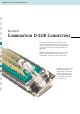
Com b i n at i o n D - S U B Connectors Section 6 Combination D-SUB Connectors Combination D-SUB Connectors provide the ideal solution for applications to require power, signal and coaxial connections within one connector. This series of connectors achieves space saving on PCB‘s and I O designs. Within this product family are various pin out configurations possible. Almost endless selections can be created mixing power, signal and coaxial contacts.
Combination D-SUB C o n n e c t o r s Industry standard terminations types, solder cup, PCB contacts in straight and angled pin configurations. Crimp types and wire wrap contacts.
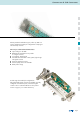
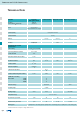
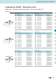
Com b i n at i o n D - S U B Connectors Mating conditions Float mount tolerance guide Rigid mount tolerance guide Rigid mount vertical to tolerance guide Panel cut-out Rear panel mounting 6| 2 Front panel mounting Shell size A ± 0,13 B ± 0,13 C ± 0,13 D ± 0,13 E ± 0,13 1 2 3 4 5 20.50 28.80 42.50 59.10 56.30 22.20 30.50 44.30 60.70 58.30 25.00 33.30 47.04 63.50 61.10 11.40 11.40 11.40 11.40 14.10 13.00 13.00 13.00 13.00 15.
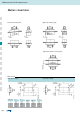
Combination D-SUB C o n n e c t o r s Part Number Creator 3 003W3 S X X 6 1 A 1 O X Product Line 3 = Shell steel tin plated 1 = Brass tin plated* A = Stainless steel* *on request Shell size and design 1 = 5W1, 2W2C 2 = 3W3, 7W2, 11W1, 3W3C 3 = 5W5, 9W4, 13W3, 17W2, 21W1 4 = 8W8, 13W6, 17W5, 21WA4, 25W3, 27W2 5 = 24W7, 36W4, 43W2, 47W1 Empty positions ADD „0“ = 003W3 Contact type P = Plug connector S = Socket connector Oberfläche Quality class for signal contacts A = Quality class 3 = 50 mating cycles B
Com b i n at i o n D - S U B Connectors Technical Data Materials Insulator Green standard black crimp Shell Connector with signal contacts Coaxial contacts High power contacts High voltage contacts PBTP, GV (UL94 V-O) steel tin plated Brass or stainless steel on request Contact plating Gold plated over nickel Contact material CU alloy PCB clip Insulator CU alloy PTFE PBTP PI CU alloy PI PTFE Mechanical and electrical characteristics Current rating Test voltage between 2 contacts conta
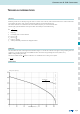
Combination D-SUB C o n n e c t o r s Technical informations Skin effect Alternating currents do not uniformly occupy the entire cross section of the conductor, rather inductance effect in the conductor deflects the current towards the surface of the conductor, whereby this deflection increases with the frequency. The resistive attenuation of a transmission line increases with the frequency as a result of this skin effect.
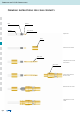
Com b i n at i o n D - S U B Connectors Crimping instructions for coax contacts Braid Insulation Dielectric Inner conductor Strip the wire Sleeve Slide sleeve over coax cable Inner contact Crimp the inner contact on the inner conductor Outer contact Snap the inner contact into the outer contact Slide braid over outer contact Crimp the sleeve on to outer contact 6| 6
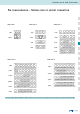
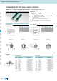
Combination D-SUB C o n n e c t o r s Pin configuration – Mating side of socket connector Shell size 1 Shell size 3 Shell size 2 5W1 3W3 5W5 2W2C 3W3C 9W4 7W2 13W3 11W1 17W2 21W1 Shell size 4 8W8 Shell size 5 24W7 13W6 36W4 17W5 43W2 21WA4 25W3 47W1 27W2 Connectors 3W3, 5W5 and 8W8 with female insulators: Socket contacts are fingerprobe safe according to UL 1950 and CSA 22.2.950.
Com b i n at i o n D - S U B Connectors Combination D-SUB with signal contacts Solder cup – Precision machined contacts – For wire size AWG 20 Description Suitable for wire size AWG 20 Mounting styles: - with through-hole, Ø .118” 3 mm - with 4-40 UNC or M3 threaded insert - with floating mount Quality class 3 (also available in quality class 1) Shell: Steel tin plated (brass tin plated or stainless steel available on request) RoHS compliant – CSA listed, File No.: LR 115000-1–UL listed, File No.
Combination D-SUB C o n n e c t o r s Combination D-SUB – Mounting styles Solder cup – Precision machined contacts – For wire size AWG 20 Order data Socket connector Plug connector Design Mounting style M3 Part Number 5W1 7W2 11W1 9W4 13W3 17W2 21W1 13W6 17W5 21WA4 25W3 27W2 24W7 36W4 43W2 47W1 Threaded insert Threaded insert Threaded insert Threaded insert Threaded insert Threaded insert Threaded insert Threaded insert Threaded insert Threaded insert Threaded insert Threaded insert Threaded insert T
Com b i n at i o n D - S U B Connectors Combination D-SUB with signal contacts Solder pin – Straight – Precision machined contacts Description Mounting styles: - with through-hole, Ø .118” 3 mm - with 4-40 UNC or M3 threaded insert - with 4-40 UNC or M3 threaded rear spacer Quality class 3 (also available in quality class 1) Shell: Steel tin plated (brass tin plated or stainless steel available on request) RoHS compliant – CSA listed, File No.: LR 115000-1–UL listed, File No.
Combination D-SUB C o n n e c t o r s Combination D-SUB – Mounting styles Solder pin – Straight – Precision machined contacts Order data Socket connector Plug connector Design Mounting style M3 Part Number 5W1 7W2 11W1 9W4 13W3 17W2 21W1 13W6 17W5 21WA4 25W3 27W2 24W7 36W4 43W2 47W1 Threaded insert Threaded insert Threaded insert Threaded insert Threaded insert Threaded insert Threaded insert Threaded insert Threaded insert Threaded insert Threaded insert Threaded insert Threaded insert Threaded inse
Com b i n at i o n D - S U B Connectors Combination D-SUB with signal contacts Solder pin – Straight – Precision machined contacts Description RoHS compliant – CSA listed, File No.: LR 115000-1–UL listed, File No.: E 228329 Socket connector Threaded rear spacer .291" 7.
Combination D-SUB C o n n e c t o r s Combination D-SUB – Mounting styles Solder pin – Straight – Precision machined contacts Order data Socket connector 7,4 ± 0,25 11,0 ± 0,25 PCB thickness .091“ 2.
Com b i n at i o n D - S U B Connectors Combination D-SUB with signal contacts Solder pin – Straight – Precision machined contacts Description RoHS compliant – CSA listed, File No.: LR 115000-1–UL listed, File No.: E 228329 Socket connector Threaded rear spacer .256“ 6.5 mm Mounting style: with 4-40 UNC threaded rear spacer with PCB clip for PCB thickness .063“ 1.6 mm for PCB thickness .091“ 2.3 mm for PCB thickness .126“ 3.
Combination D-SUB C o n n e c t o r s Combination D-SUB – Mounting styles Solder pin – Straight – Precision machined contacts Order data Socket connector 6,5 ± 0,25 10,1 ± 0,25 PCB thickness .091“ 2.
Com b i n at i o n D - S U B Connectors Combination D-SUB with signal contacts Press-fit – Straight – Precision machined contacts Description Mounting styles: - with 4-40 UNC or M3 threaded rear spacer - with M3 or 4-40 UNC rear press-fit spacer Quality class 3 (also available in quality class 1) Shell: Steel tin plated (brass tin plated or stainless steel available on request) RoHS compliant – CSA listed, File No.: LR 115000-1–UL listed, File No.
Combination D-SUB C o n n e c t o r s Combination D-SUB – Mounting styles Press-fit – Straight – Precision machined contacts Order data Socket connector Plug connector Design Mounting style 4-40 UNC Part Number 5W1 7W2 11W1 9W4 13W3 17W2 21W1 13W6 17W5 21WA4 25W3 27W2 24W7 36W4 43W2 47W1 Threaded rear spacer Threaded rear spacer Threaded rear spacer Threaded rear spacer Threaded rear spacer Threaded rear spacer Threaded rear spacer Threaded rear spacer Threaded rear spacer Threaded rear spacer Thread
Com b i n at i o n D - S U B Connectors Combination D-SUB with signal contacts Wire wrap – 3 level – Precision machined contacts Description Mounting styles: - with through-hole, Ø .118” 3 mm - with 4-40 UNC or M3 threaded insert Quality class 3 (also available in quality class 1) Shell: Steel tin plated (brass tin plated or stainless steel available on request) RoHS compliant – CSA listed, File No.: LR 115000-1–UL listed, File No.: E 228329 Socket connector Plug connector Shell size A -0.76 B -0.
Combination D-SUB C o n n e c t o r s Combination D-SUB – Mounting styles Wire wrap – 3 level – Precision machined contacts Order data Socket connector Plug connector Design Mounting style M3 Part Number 5W1 7W2 11W1 9W4 13W3 17W2 21W1 13W6 17W5 21WA4 25W3 27W2 24W7 36W4 43W2 47W1 Threaded insert Threaded insert Threaded insert Threaded insert Threaded insert Threaded insert Threaded insert Threaded insert Threaded insert Threaded insert Threaded insert Threaded insert Threaded insert Threaded insert
Com b i n at i o n D - S U B Connectors Combination D-SUB with signal contacts Solder pin – Angled – .318" 7.
Combination D-SUB C o n n e c t o r s Combination D-SUB – Mounting styles Solder pin – Angled – .318“ 7.
Com b i n at i o n D - S U B Connectors Combination D-SUB with signal contacts Solder pin – Angled – .370“ 9.
Combination D-SUB C o n n e c t o r s Combination D-SUB – Mounting styles Solder pin – Angled – .370“ 9.
Com b i n at i o n D - S U B Connectors Combination D-SUB without contacts For straight high power, coaxial or high voltage contacts Description Designs: 2W2C; 3W3; 3W3C; 5W5; 8W8 Mounting styles: - with through-hole, Ø .118” 3 mm - with 4-40 UNC threaded insert - with 4-40 UNC threaded rear spacer - with 4-40 UNC threaded rear spacer with PCB clip .291” 7.4 mm for PCB thickness .063” 1.6 mm, .091” 2.3 mm, .126” 3.2 mm On request: Threaded rear spacer with PCB clip .256” 6.
Combination D-SUB C o n n e c t o r s Combination D-SUB – Mounting styles For straight high power, coaxial or high voltage contacts Order data Socket connector Design Mounting style 4-40 UNC 3W3 Threaded rear spacer 5W5 Threaded rear spacer 8W8 Threaded rear spacer Coded version 2W2C Threaded rear spacer 3W3C Threaded rear spacer Plug connector Part Number Design 3 003W3SXX99A50 X 3 005W5SXX99A50 X 3 008W8SXX99A50 X 3W3 Threaded rear spacer 5W5 Threaded rear spacer 8W8 Threaded rear spacer Coded vers
Com b i n at i o n D - S U B Connectors Combination D-SUB without contacts For angled high power or coaxial contacts – Short metal bracket Description Designs: 2W2C; 3W3; 3W3C; 5W5; 8W8 Mounting styles: - Mounting bracket and 4-40 UNC threaded insert - Mounting bracket with 4-40 UNC front spacer - Mounting bracket, PCB clip and 4-40 UNC threaded insert - Mounting bracket, PCB clip and 4-40 UNC front spacer M3 thread design available on request Shell: Steel tin plated (brass tin plated or stainless steel av
Combination D-SUB C o n n e c t o r s Combination D-SUB – Mounting styles For angled high power or coaxial contacts – Short metal bracket Order data Socket connector Design Plug connector Mounting style 4-40 UNC 3W3 Front spacer 5W5 Front spacer 8W8 Front spacer Coded version 2W2C Front spacer 3W3C Front spacer Part Number Design 3 003W3SXX99P20 X 3 005W5SXX99P20 X 3 008W8SXX99P20 X 3W3 Front spacer 5W5 Front spacer 8W8 Front spacer Coded version 2W2C Front spacer 3W3C Front spacer 3 02W2CSXX99P20
Com b i n at i o n D - S U B Connectors Combination D-SUB without contacts For angled high power or coaxial contacts – Long metal bracket Description Designs: 2W2C; 3W3; 3W3C; 5W5; 8W8 Mounting styles: - with mounting bracket and 4-40 UNC threaded insert - with mounting bracket with 4-40 UNC front spacer - with mounting bracket, PCB clip and 4-40 UNC threaded insert - with mounting bracket, PCB clip and 4-40 UNC front spacer M3 thread design available on request Shell: Steel tin plated (brass tin plated or
Combination D-SUB C o n n e c t o r s Combination D-SUB – Mounting styles For angled high power or coaxial contacts – Long metal bracket Order data Socket connector Design Plug connector Mounting style 4-40 UNC 3W3 Front spacer 5W5 Front spacer 8W8 Front spacer Coded version 2W2C Front spacer 3W3C Front spacer Part Number Design 3 003W3SXX99H20 X 3 005W5SXX99H20 X 3 008W8SXX99H20 X 3W3 Front spacer 5W5 Front spacer 8W8 Front spacer Coded version 2W2C Front spacer 3W3C Front spacer 3 02W2CSXX99H20 X
Com b i n at i o n D - S U B Connectors Combination D-SUB Crimp body (without contacts) – For wire size AWG 20…24 and AWG 26…28 Description For precision machined contacts for wire size AWG 20…24 and AWG 26…28 Mounting styles: - with through-hole, Ø .118” 3 mm - with 4-40 UNC or M3 threaded insert Shell: Steel tin plated (brass tin plated or stainless steel available on request) RoHS compliant – CSA listed, File No.: LR 115000-1–UL listed, File No.
Combination D-SUB C o n n e c t o r s Combination D-SUB – Mounting styles Crimp body (without contacts) – For wire size AWG 20…24 and AWG 26…28 Order data Socket connector Plug connector Design Mounting style M3 Part Number 5W1 7W2 11W1 9W4 13W3 17W2 21W1 13W6 17W5 21WA4 25W3 27W2 24W7 36W4 43W2 47W1 Threaded insert Threaded insert Threaded insert Threaded insert Threaded insert Threaded insert Threaded insert Threaded insert Threaded insert Threaded insert Threaded insert Threaded insert Threaded in
Com b i n at i o n D - S U B Connectors Combination D-SUB Contacts Crimp contacts – Precision machined – For wire size AWG 20…24 and AWG 26…28 Description For wire size AWG 20…24 and AWG 26–28 Quality class 3, quality class 1 also available Other quality classes on request RoHS compliant – CSA listed, File No.: LR 115000-1–UL listed, File No.
Combination D-SUB C o n n e c t o r s Combination D-SUB Contacts High power contacts – Solder cup – Straight Description Precision machined contacts Quality class 3: 50 mating cycles (gold plated) Quality class 1: 500 mating cycles (gold plated) Other quality classes on request Assembled at shell available on request Selective gold plated contacts available on request (soldering tin plated) RoHS compliant – CSA listed, File No.: LR 115000-1–UL listed, File No.
Com b i n at i o n D - S U B Connectors Combination D-SUB Contacts High power contacts – Screw termination – Straight – For wire size AWG 14 Description Precision machined contacts for wire size AWG 14, max. 20 A Quality class 3: 50 mating cycles (gold plated) Quality class 1: 500 mating cycles (gold plated) Other quality classes on request For field attachable applications RoHS compliant – CSA listed, File No.: LR 115000-1–UL listed, File No.
Combination D-SUB C o n n e c t o r s Combination D-SUB Contacts High power contacts – Crimp – Straight Description Precision machined contacts Quality class 3: 50 mating cycles (gold plated) Quality class 1: 500 mating cycles (gold plated) Other quality classes on request Tools: Section 14 RoHS compliant – CSA listed, File No.: LR 115000-1–UL listed, File No.: E 228329 Product drawing Socket contact AWG Current rating ØA+0.15 16-20 10 A 1.70 12-14 20 A 2.60 10-12 30 A 3.70 8-10 40 A 4.
Com b i n at i o n D - S U B Connectors Combination D-SUB Contacts High power contacts – Solder cup or crimp – angled Description Precision machined contacts Quality class 3: 50 mating cycles (gold plated) Quality class 1: 500 mating cycles (gold plated) Other quality classes on request RoHS compliant – CSA listed, File No.: LR 115000-1–UL listed, File No.
Combination D-SUB C o n n e c t o r s Combination D-SUB Contacts High power contacts – Solder pin – angled Description Precision machined contacts Quality class 3: 50 mating cycles (gold plated) Quality class 1: 500 mating cycles (gold plated) Other quality classes on request RoHS compliant – CSA listed, File No.: LR 115000-1–UL listed, File No.
Com b i n at i o n D - S U B Connectors Combination D-SUB Contacts High power contacts – Solder pin – Straight Description Precision machined contacts Quality class 3: 50 mating cycles (gold plated) Quality class 1: 500 mating cycles (gold plated) Other quality classes on request Assembled at shell available on request RoHS compliant – CSA listed, File No.: LR 115000-1–UL listed, File No.
Combination D-SUB C o n n e c t o r s Combination D-SUB Contacts High voltage contacts – Solder termination – Straight and angled – For wire size AWG 20 Description Precision machined contacts for wire size AWG 20, max. 2,8 kV Quality class 1: 500 mating cycles (gold plated) Other quality classes on request RoHS compliant – CSA listed, File No.: LR 115000-1–UL listed, File No.
Com b i n at i o n D - S U B Connectors Combination D-SUB Contacts Coaxial contacts – Straight – Inner conductor solder-, outer conductor crimpsolder termination Description 50 and 75 Ω-design Contact platings: - .051 µ“ 1.3 µm Au mating side inner conductor .032 µ“ 0.8 µm Au outer conductor - .008 µ“ 0.2 µm Au mating side inner- and outer conductor Other platings are available Delivery includes: contacts and sleeve supplied loose RoHS compliant – CSA listed, File No.
Combination D-SUB C o n n e c t o r s Combination D-SUB Contacts Coaxial contacts – Straight – Inner and outer conductor crimp termination Description 50 and 75 Ω design Contact platings: - .051 µ“ 1.3 µm Au mating side inner conductor .032 µ“ 0.8 µm Au outer conductor - .008 µ“ 0.2 µm Au mating side inner- and outer conductor Quality class 1: 500 mating cycles (gold plated) Delivery includes: contacts and sleeve supplied loose RoHS compliant – CSA listed, File No.: LR 115000-1–UL listed, File No.
Com b i n at i o n D - S U B Connectors Combination D-SUB Contacts Coaxial contacts – Angled – Inner conductor solder-, outer conductor crimpSolder termination Description 50 Ω design Contact platings: - .051 µ“ 1.3 µm Au mating side inner conductor .032 µ“ 0.8 µm Au outer conductor - .008 µ“ 0.2 µm Au mating side inner- and outer conductor Quality class 1: 500 mating cycles (gold plated) Delivery includes: contacts and sleeve supplied loose RoHS compliant – CSA listed, File No.
Combination D-SUB C o n n e c t o r s Combination D-SUB Contacts Coaxial contacts – Angled – Inner- and outer conductor crimp termination Description 50 and 75 Ω design Contact platings: - .051 µ" 1.3 µm Au mating side inner conductor .032 µ“ 0.8 µm Au outer conductor - .008 µ“ 0.2 µm Au mating side inner- and outer conductor Quality class 1: 500 mating cycles (gold plated) Delivery includes: contacts and sleeve supplied loose RoHS compliant – CSA listed, File No.: LR 115000-1–UL listed, File No.
Com b i n at i o n D - S U B Connectors Combination D-SUB Contacts Coaxial contacts – Straight – PCB termination – 3 solder pins Description 50 and 75 Ω design Contact finishings: - .051 µ“ 1.3 µm Au mating side inner conductor .032 µ“ 0.8 µm Au outer conductor - .008 µ“ 0.2 µm Au mating side inner- and outer conductor Quality class 1: 500 mating cycles (gold plated) RoHS compliant – CSA listed, File No.: LR 115000-1–UL listed, File No.
Combination D-SUB C o n n e c t o r s Combination D-SUB Contacts Coaxial contacts – Angled – PCB termination – 3 solder pins Description 50 and 75 Ω design Contact platings: - .051 µ“ 1.3 µm Au mating side inner conductor .032 µ“ 0.8 µm Au outer conductor - .008 µ“ 0.2 µm Au mating side inner- and outer conductor Quality class 1: 500 mating cycles (gold plated) RoHS compliant – CSA listed, File No.: LR 115000-1–UL listed, File No.
Com b i n at i o n D - S U B Connectors Combination D-SUB Contacts Coaxial contacts – Angled – PCB termination – 5 solder pins Description 50 and 75 Ω design For mounting connector on edge of PCB without metal bracket Contact platings: - .051 µ“ 1.3 µm Au mating side inner conductor .032 µ“ 0.8 µm Au outer conductor - .008 µ“ 0.2 µm Au mating side inner- and outer conductor Quality class 1: 500 mating cycles (gold plated) RoHS compliant – CSA listed, File No.: LR 115000-1–UL listed, File No.
Combination D-SUB C o n n e c t o r s Combination D-SUB Accessories Grounding for coaxial contacts Ground strap To optimize a perfect ground connection from the coaxial contact (outer conductor) to the metal shell. (Factory installed).. Guide post For safe mating of male and female connectors with contact loss. Guide post can be installed after connector is mounted. Part Number Guide post 160 X 11279 X Hole plug The hole plug can be used for both male and female connector.
Com b i n at i o n D - S U B Connectors Combination D-SUB – Dual port with contacts loaded Solder pin – Angled – Precision machined contacts – Connector spacing .
Combination D-SUB C o n n e c t o r s Combination D-SUB – Dual port variations Solder pin – Angled – Precision machined contacts – Connector spacing .750“ 19,05 mm Order data Type 2 x 5W1 2 X 7W2 2 X 13W3 2 X 17W2 2 X 17W5 Mounting style 4-40 UNC Part Number No. of pos.
Com b i n at i o n D - S U B Connectors Combination D-SUB – Dual port with loaded contacts Solder pin – Angled – Precision machined contacts – Connector spacing .
Combination D-SUB C o n n e c t o r s Combination D-SUB – Dual port variations Solder pin – Angled – Precision machined contacts – Connector spacing .750“ 19,05 mm Order data Type 2 X 2W2C 2 X 3W3 2 X 3W3C 2 X 5W5 2 X 8W8 Mounting style 4-40 UNC Part Number No. of pos.