
Manual

6
|
4
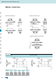
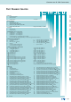
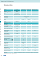
Technical Data
Materials Connector
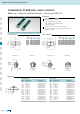
with signal contacts
Coaxial contacts High power contacts High voltage contacts
PBTP, GV
(UL94 V-O)
steel tin plated
Brass or stainless steel on request
Gold plated over nickel
CU alloy
CU alloy CU alloy PI
PTFE
PBTP PI PTFE
7.5 A (UL)
5 A (CSA, VDE)
1000 V, 50Hz
1 min.
2.7mΩ
5GΩ 10
7
mΩ 5GΩ 2x10
7
mΩ
10
16
Ωcm
50KV
mm
50
75
2.7mΩ 2.7mΩ 1mΩ 2.7mΩ
1.2
1.3
1.5
750V 50Hz 3.8kV
0-2GHz
250 V 250 V max. 2.8kV
-55°C to +125°C
3,4N 7N 7N 5N
0,2N 7N ca. 5N ca. 2.5N
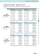
A = Quality class 3 = 50 mating cycles, B = Quality class 2 = 200 mating cycles, C = Quality class 1 = 500 mating cycles
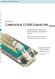
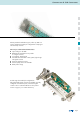
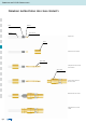
Combination D-SUB Connectors
Technical alterations are subject to change without notice.
Mechanical and electrical
characteristics
Insulator
Green standard
black crimp
Shell
Contact plating
Contact material
PCB clip
Insulator
Current rating
Test voltage between 2 contacts
contact and shell
Resistance between mated contacts
Insulation resistance
Contact resistance
Dielectric impedance
Characteristic impedance
Contact resistance inner
outer conductor
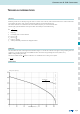
VSWR-value at according
MIL-C-39012
1.2GHz
1.5GHz
2.0GHz
Dielectric voltage
Frequency range
Working voltage
Temperature range
Insertion force per contact
Extraction force per contact
Mating cycles