
Owner's manual


4
|
3
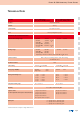
Technical Data
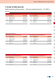
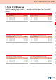
Fil te r D- SU B A da pt er s, Fi lt er P la te s
Technical alterations are subject to change without notice.
Insulator
Contacts
Contact plating
Shell
Dielectric with standing voltage
Working voltage
Contact resistance
Insulation resistance
Current rating
Voltage surge 10
700µs
Mating and unmating forces
Temperature working range
Humidity
Capacitor values
For other capacitance values please contact the factory.
Quality class
Materials
Polyester GF UL94 V-0
CU alloy
Gold plated over nickel
Steel tin plated
brass tin plated
• Standard 424 VDC • Standard 300 VDC
• Standard 300 VDC
(for -Filter)
• High DWV 707 VDC
• Ultra high DWV 1500 VDC *
• Ultra high DWV 1000 VDC *
(for -Filter)
*on request
• Standard 100 VDC* • Standard 100 VDC*
• High DWV 100 VDC*
• Ultra high DWV 200 VDC*
*Depending on isolation coordination (refer to DIN VDE 0110
IEC 664-1)
Max. 10 mΩ prior to stressing, Δ R max. 10 mΩ after stressing
per DIN 41652, Part 2
≥ 1GΩ
7.5 A (UL)
5 A (CSA,VDE) 3 A (UL,VDE) 2.5 A (CSA)
Standard 300 V Standard 300 V
High voltage 500 V
9 pos. ≤ 30 N 15 pos. ≤ 50 N
15 pos. ≤ 50 N 26 pos. ≤ 83 N
25 pos. ≤ 83 N 44 pos. ≤ 110 N
37 pos. ≤ 123 N 62 pos. ≤ 170 N
50 pos. ≤ 167 N
-25°C to +105° C -25°C to +85°C
40°C
85% relative humidity
RH
180 pF ± 20% tolerance 180 pF ± 20% tolerance
370 pF ± 20% tolerance 370 pF ± 20% tolerance
830 pF ± 20% tolerance 830 pF ± 20% tolerance
1300 pF ± 20% tolerance
other capacitor values on request
A = Quality class 3 = 50 mating cycles
B = Quality class 2 = 200 mating cycles
C = Quality class 1 = 500 mating cycles
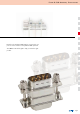
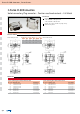
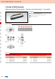
Filter D-SUB Adapter
9, 15, 25, 37 and 50 position
Filter D-SUB Adapter High-Density
15-, 25-, 44-, and 78 position
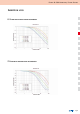
Mechanical and electrical characteristics