
Instruction Manual

2
|
43
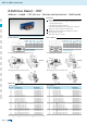
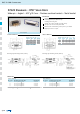
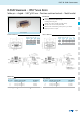
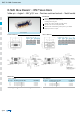
PCB layout Kat1iT9A PCB layout Kat1iU0A
RoHS compliant
No. of pos. A
+ 0.2
- 0
B
+ 0
- 0.25
C D
15 39.40 16.81 25.00
+ 0.12
- 0.13
6.00
+ 0.12
- 0.18
26 47.70 25.14 33.32
+ 0.13
- 0.12
6.00
+ 0.12
- 0.18
44 61.40 38.86 47.04
± 0.13
5.99
+ 0
- 0,3
62 78.00 55.32 63.50
± 0.13
5.99
+ 0
- 0,3
No. of pos. A
+ 0.2
- 0
B
+ 0
- 0,25
C
15 39.40 16.46 25.00
+ 0.12
- 0.13
26 47.70 24.79 33.32
+ 0.13
- 0.12
44 61.40 38.50 47.04
± 0.13
62 78.00 54.96 63.50
± 0.13
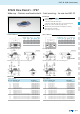
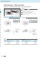
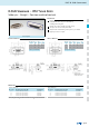
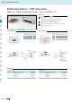
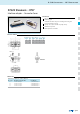
IP67 D-SUB Connectors
Description
Order data
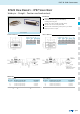
Socket connector Plug connector
D-SUB High Density – IP67 Solid Body
Solder pin – Straight – Precision machined contacts
PCB clip .122” 3.1 ± .004” 0.10 mm hole diameter and .063” 1.6 mm circuit board thickness
Plug connector
No. of pos. Mounting style 4-40 UNC Part Number
15 Threaded rear spacer PCB clip 15-000493
26 Threaded rear spacer PCB clip 15-000503
44 Threaded rear spacer PCB clip 15-000513
62 Threaded rear spacer PCB clip 15-000523
Mounting style:
4-40 UNC threaded rear spacer with PCB clip
including hex locking bolt
Quality class 3 (also available in quality class 1)
One-piece zinc die-cast nickel plated shell
IP67 for harsh environments, pressure-proof up to 1.45 PSI
Higher protection on request
Socket connector
No. of pos. Mounting style 4-40 UNC Part Number
15 Threaded rear spacer PCB clip 15-000533
26 Threaded rear spacer PCB clip 15-000543
44 Threaded rear spacer PCB clip 15-000553
62 Threaded rear spacer PCB clip 15-000563