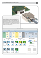
05. Subminiature D Connectors D-Sub connectors are an Industry Standard for cable-to-board connectivity applications. Thanks to the large variety of solutions it offers, it can be universally used as a device interface. Our customers manufacturing requirements are addressed by the comprehensive range of PCB termination styles available. It is particularly suited to configuring communication and data interfaces and is the standard for many fieldbus profiles.
05. Subminiature D Connectors Page D-Sub connector system – introduction 05.02 D-Sub Standard connectors (D-Sub – S) 05.04 D-Sub High Density connectors (D-Sub – HD) 05.36 D-Sub Mixed connectors (D-Sub – M) 05.48 D-Sub Filter connectors (D-Sub – F) 05.90 D-Sub Waterproof IP 67 connectors (D-Sub – W) 05.126 D-Sub Housing range (D-Sub – H) and accessories 05.150 D-Sub Standard press-in connectors 05.173 D-Sub Standard SMC connectors 05.178 D-Sub Standard SMT connectors 05.
D-Sub 05. Subminiature D Connectors In the automation industry, the Subminiature D connectors are Depending on the product family, various termination techniques the standard interfaces for data, signal and service/programmer can be supplied such as press-in, solder, SMC or SMT to match the interfaces. The extensive HARTING product range allows the set customer’s termination process.
Specific fe atures of the product r ange D-Sub – Mixed connectors with nearly 20 different contact arrangements offering versatile options for mixing power, coaxial, high voltage, signal and even D-Sub pneumatic contacts in one connector. D-Sub – Waterproof IP 65 / IP 67 connectors with 9 to 50 contacts for panel mount to PCB or cable. D-Sub – Filter connectors with 9 to 37 contacts and integrated, different filter designs, like C, L or Pi types.
PCB solder version Number of contacts 9, 15, 25, 37, 50 UL recognized Working current D-Sub see current carrying capacity chart 7.5 A max. Turned contacts 6.5 A max. Stamped contacts Test voltage Ur.m.s. 1 kV Clearance and creepage ≥ 1.0 mm Contact resistance Insulation resistance ≤ 10 mΩ ≥ 1010 Ω Technical characteristics Current carrying capacity The current carrying capacity is limited by maximum temperature of materials for inserts and contacts including terminals.
D-Sub Notes 05 05
D-Sub DIN 41 652 · CECC 75 301-802 Number of contacts 9--50 Turned solder pins, straight Identification D-Sub Performance levels Explanations see page 05.04 Other performance levels on request þ No. of contacts Part No.
D-Sub DIN 41 652 · CECC 75 301-802 Number of contacts 9--50 Turned solder pins, straight without grounding-pins Performance levels Explanations see page 05.04 Other performance levels on request þ No. of contacts Part No.
D-Sub DIN 41 652 · CECC 75 301-802 Number of contacts 9--50 Stamped solder pins, straight with/without grounding board locks Identification D-Sub Performance levels Explanations see page 05.04 Other performance levels on request þ No. of contacts Part No. Performance level Performance level 3 2 Male connector metal shell with dimples Without grounding board locks With grounding board locks 9 09 65 121 770 . 09 65 121 670 . 15 09 65 221 770 . 09 65 221 670 . 25 09 65 321 770 .
D-Sub DIN 41 652 · CECC 75 301-802 Number of contacts 9--50 Stamped solder pins, straight with/without grounding board locks Male connector 9 – 37 contacts Drawing No. 1 contact Dimensions in mm Mating face acc. to: DIN 41 652 · CECC 75 301-802 IEC 60 807 D-Sub Identification Nut thread Female connector 9 – 37 contacts Mating face acc. to: DIN 41 652 · CECC 75 301-802 · IEC 60 807 No. 1 contact Nut thread a b ± 0.1 c g h 9 30.9 25.0 12.5 4 x 2.74 = 10.96 3 x 2.74 = 8.22 15 39.
D-Sub Front panel width Mounting details – angled solder pins 3 TE 3 x 5.08 mm s on .21 i s er 05 eV 8– l .1 ofi es 05 r P g wLo pa D-Sub 9-37 way Front panel width s s ion .23 on 5.17 s i r 5 s r 0 Ve 0 Ve .12 – nt .22 – i r d 5 5 r tp da ges 0 oo ages 0 n F a . a p p St U.S 4 TE 4 x 5.08 mm 9-37 way 50 way Front panel width 5 TE 5 x 5.
D-Sub Mounting details – angled solder pins Advantages All-round protective metal shell ● Polarisation ● Contact protection ● Plated shell ● Male connector with dimples Contact surface finish to different performance levels Plated terminations for increased solderability Different metal threads possible in flange area ● M3 ● 4-40 UNC ● fitted female screw locks 4-40 UNC ● max. torque ≤ 0.
D-Sub DIN 41 652 · CECC 75 301-802 Number of contacts Mounting height Standard Versions 9--37 50 Turned solder pins, angled with/without snap-in-clips and grounding board locks D-Sub Identification Performance levels Explanations see page 05.04 Other performance levels on request þ No. of contacts Part No.
D-Sub DIN 41 652 · CECC 75 301-802 Number of contacts Mounting height Standard Versions 9--37 50 Turned solder pins, angled with/without snap-in-clips and grounding board locks Drawing 9-37 Male connector ith snap-in clips W and grounding board locks Dimensions in mm 50 D-Sub Identification Mating face acc. to: DIN 41 652 · CECC 75 301-802 · IEC 60 807 No. 1 contact Grounding pins 0.2 x 0.
D-Sub DIN 41 652 · CECC 75 301-802 Number of contacts Mounting height Standard Versions 9--37 50 Stamped solder pins, angled with grounding board locks Identification D-Sub Performance levels Explanations see page 05.04 Other performance levels on request þ No. of contacts Part No. Performance level Performance level 3 2 Male connector metal shell with dimples 9 15 25 37 9 15 25 37 2.84 mm pitch 2.
D-Sub DIN 41 652 · CECC 75 301-802 Number of contacts Mounting height Standard Versions 9--37 50 Stamped solder pins, angled with grounding board locks Identification Drawing Dimensions in mm Mating face acc. to: DIN 41 652 · CECC 75 301-802 IEC 60 807 D-Sub Male connector X Nut thread No. 1 contact fitted screw locks 4 - 40 UNC M3 or 4 - 40 UNC 9-37 Female connector 50 Mating face acc. to: DIN 41 652 · CECC 75 301-802 IEC 60 807 No. 1 contact X 9-37 Grounding board lock 0.2 x 0.
D-Sub DIN 41 652 · CECC 75 301-802 Number of contacts Mounting height Standard Versions 9--37 50 Stamped solder pins, angled without grounding board locks Identification D-Sub Performance levels Explanations see page 05.04 Other performance levels on request þ No. of contacts Part No. Performance level Performance level 3 2 Male connector metal shell with dimples 9 15 25 37 9 15 25 37 2.84 mm pitch 2.
D-Sub DIN 41 652 · CECC 75 301-802 Number of contacts Mounting height Standard Versions 9--37 50 Stamped solder pins, angled without grounding board locks Identification Drawing Dimensions in mm D-Sub Male connector Mating face acc. to: DIN 41 652 · CECC 75 301-802 · IEC 60 807 fitted screw locks 4 - 40 UNC Nut thread No. 1 contact M3 or 4 - 40 UNC Dimples 9-37 Female connector X 50 Mating face acc. to: DIN 41 652 · CECC 75 301-802 · IEC 60 807 No.
D-Sub DIN 41 652 · CECC 75 301-802 Number of contacts Mounting height Low-Profile Versions 9--37 50 Turned solder pins, angled with snap-in-clips and grounding board locks D-Sub Identification Performance levels Explanations see page 05.04 Other performance levels on request þ No. of contacts Part No.
D-Sub DIN 41 652 · CECC 75 301-802 Number of contacts Mounting height Low-Profile Versions 9--37 50 Turned solder pins, angled with snap-in-clips and grounding board locks Identification Drawing Dimensions in mm D-Sub Male connector 9-37 50 Mating face acc. to: DIN 41 652 · CECC 75 301-802 · IEC 60 807 No. 1 contact fitted screw locks 4 - 40 UNC X M3 or 4 - 40 UNC Y Grounding board lock 0.2 x 0.6 Y Dimples 9-37 Board drillings X 50 plated through holes a b±0.1 c f 9 30.
D-Sub DIN 41 652 · CECC 75 301-802 Number of contacts Mounting height Low-Profile Versions 9--37 50 Stamped solder pins, angled with grounding board locks Identification D-Sub Performance levels Explanations see page 05.04 Other contact surfaces on request þ No. of contacts Part No. Performance level Performance level 3 2 Male connector metal shell with dimples 9 15 25 37 09 65 162 781 09 65 262 781 09 65 362 781 09 65 462 781 . . . .
D-Sub DIN 41 652 · CECC 75 301-802 Number of contacts Mounting height Low-Profile Versions 9--37 50 Stamped solder pins, angled with grounding board locks Identification Drawing Dimensions in mm Mating face acc. to: DIN 41 652 · CECC 75 301-802 IEC 60 807 D-Sub Male connector X Nut thread No. 1 contact fitted screw locks 4 - 40 UNC M3 or 4 - 40 UNC 9-37 Female connector 50 Mating face acc. to: DIN 41 652 · CECC 75 301-802 IEC 60 807 No. 1 contact X 9-37 Grounding board lock 0.2 x 0.
D-Sub DIN 41 652 · CECC 75 301-802 U.S. Footprint Number of contacts Mounting height 9--37 Stamped solder pins, angled with snap-in-clips and grounding board locks Identification D-Sub Performance levels Explanations see page 05.04 Other performance levels on request þ No. of contacts Part No. Performance level 3 S41) Male connector metal shell with dimples 9 15 25 37 2.84 mm pitch 2.84 mm pitch 09 68 163 781 09 68 263 781 09 68 363 781 09 68 463 781 . . . .
D-Sub DIN 41 652 · CECC 75 301-802 U.S. Footprint Number of contacts Mounting height 9--37 Stamped solder pins, angled with snap-in-clips and grounding board locks Male connector Drawing Dimensions in mm Mating face acc. to: DIN 41 652 · CECC 75 301-802 IEC 60 807 X No. 1 contact D-Sub Identification Y plated through holes Dimples Female connector Mating face acc. to: DIN 41 652 · CECC 75 301-802 No.
D-Sub Identification Mounting details Drawing Dimensions in mm Standard Versions plated through hole Mounting height 7.3 mm 9-37 way for front panel 4 units of width (TE) D-Sub Mounting height 8.7 mm only for snap-in-clips version 50 way for front panel 5 units of width (TE) Ø 3.1 ± 0.1 All holes Ø 1 ± 0.1 for connectors see pages 05.12 – 05.17 Low-Profile Versions Mounting height 3.
Number of contacts 9, 15, 25, 37, 50 UL recognized Working current see current carrying capacity chart Turned contacts 7.5 A max. Stamped contacts 6.5 A max. 2.0 A max. Insulation displacement Test voltage Ur.m.s. 1 kV Clearance and creepage ≥ 1.0 mm ≥ 0.
D-Sub DIN 41 652 · CECC 75 301-802 Number of contacts 9--50 Crimp terminal D-Sub Identification Male connector Order contacts separately metal shell with dimples Female connector Order contacts separately metal shell No. of contacts Part No.
D-Sub DIN 41 652 · CECC 75 301-802 Turned crimp contacts Individual contacts1) 1) inimum order 100 pieces M or multiples of 100 Wire gauge (mm2) Part No. Male contacts Female contacts High-end female contacts Performance level Performance level Performance level 1* 1* 1* AWG 22-18 0.33-0.82 09 67 000 3576 09 67 000 3476 09 67 000 3676 AWG 24-20 0.25-0.52 09 67 000 8576 09 67 000 8476 09 67 000 8676 AWG 26-22 0.13-0.33 09 67 000 5576 09 67 000 5476 09 67 000 5676 AWG 28-24 0.
D-Sub DIN 41 652 · CECC 75 301-802 Stamped crimp contacts Wire gauge (mm2) Identification D-Sub Performance levels Explanations see page 05.04 Other performance levels on request Individual contacts 500 pieces/reel þ Part No. stamped male contacts AWG 28-24 0.09-0.
D-Sub DIN 41 652 · CECC 75 301-802 Stamped crimp contacts Male contacts Drawing Dimensions in mm For bandoliered contacts only D-Sub Identification Contact identification AWG 20-24 24-28 C 2.46 1.65 D 1.78 1.47 E 1.98 1.52 F 1.90 1.52 RA 0.71 0.50 RB Contact identification 0.43 –––– 0.
D-Sub DIN 41 652 · CECC 75 301-802 Stamped crimp contacts Wire gauge (mm2) Identification D-Sub Performance levels Explanations see page 05.04 Other performance levels on request Individual contacts 500 pieces/reel þ Part No. stamped female contacts AWG 28-24 0.09-0.
D-Sub DIN 41 652 · CECC 75 301-802 Stamped crimp contacts Female contacts Drawing Dimensions in mm For bandoliered contacts only D-Sub Identification Contact identification AWG 20-24 24-28 C 2.46 1.65 D 1.78 1.47 E 1.98 1.52 F 1.90 1.52 RA 0.71 0.50 RB Contact identification 0.43 –––– 0.
D-Sub DIN 41 652 · CECC 75 301-802 Number of contacts 9--37 Insulation displacement termination Identification D-Sub Performance levels Explanations see page 05.04 Other performance levels on request þ No. of contacts Part No. Performance level Performance level 3 2 Male connector2) pitch 1.27 mm metal shell with dimples 9 15 25 37 09 66 128 770 09 66 228 770 09 66 328 770 09 66 428 770 . . . . 09 66 128 670 09 66 228 670 09 66 328 670 09 66 428 670 . . . .
D-Sub DIN 41 652 · CECC 75 301-802 Number of contacts 9--37 Insulation displacement termination Male connector Drawing Dimensions in mm 4/40 UNC-2B D-Sub Identification 2.77 TYP. 18.20 ± 0.38 after crimping position 20.80 ± 0.38 pre-crimp position Dimples Female connector 4/40 UNC-2B 2.77 TYP. 18.20 ± 0.38 after crimping position 20.65 ± 0.
D-Sub DIN 41 652 · CECC 75 301-802 Number of contacts 9--50 Solder buckets D-Sub Identification Performance levels Explanations see page 05.04 Other performance levels on request þ No. of contacts Part No.
D-Sub DIN 41 652 · CECC 75 301-802 Number of contacts 9--50 Solder buckets Identification Drawing Dimensions in mm D-Sub Male connector Dimples Female connector 9 15 25 37 50 Panel cut out for front/rear mount Values are taken from the CECC 75 301-802 a 30.9 39.2 53.1 69.4 67.0 b ± 0.1 25.0 33.3 47.0 63.5 61.1 c 12.5 12.5 12.5 12.5 15.4 see page 05.24 05 35 Mating conditions see page 05.
D-Sub high density connectors Number of contacts 15, 26, 44, 62, 78 Working current Stamped contacts D-Sub Technical characteristics 2 A max. Test voltage Ur.m.s. 1 kV Clearance and creepage ≥ 1.0 mm Contact resistance < 20 mΩ < 25 mΩ (for right angled versions) ≥ 5 x 10⁹ Ω Insulation resistance Temperature range -40 OC … + 85 OC The higher temperature limit includes the local ambient and heating effect of the contacts under load Terminations a) Solder pins Ø 0.65 mm for P.C.
D-Sub Number of contacts 15--78 Identification Male connector Order contacts separately metal shell with dimples Female connector Order contacts separately metal shell No. of contacts Part No. 15 26 44 62 78 09 56 100 5601 09 56 200 5601 09 56 300 5601 09 56 400 5601 09 56 500 5601 15 26 44 62 78 09 56 100 4701 09 56 200 4701 09 56 300 4701 09 56 400 4701 09 56 500 4701 15-62 Male connector D-Sub High density crimp terminal 78 No. 1 contact 15 26 44 62 78 Female connector a 30.9 39.2 53.
D-Sub Crimp contacts for high density connectors Identification D-Sub Performance levels Explanations see page 05.04 Other performance levels on request þ Wire gauge (mm2) Part No.
D-Sub Crimp contacts for high density connectors Male contacts wire gauge AWG 26-24 Drawing Dimensions in mm D-Sub Identification Female contacts wire gauge AWG 26-24 05 39
D-Sub Number of contacts 15--78 High density with stamped solder cups, straight Identification D-Sub Performance levels Explanations see page 05.04 Other performance levels on request þ No. of contacts Part No.
D-Sub Number of contacts 15--78 High density with stamped solder cups, straight Male connector Drawing Dimensions in mm 15-62 78 15-62 D-Sub Identification 78 15 26 44 62 78 Female connector 15-62 a 30.81 39.20 53.05 69.40 67.00 78 b 25.00 33.30 47.00 63.50 61.00 c 16.92 25.25 38.96 55.42 52.81 d 19.20 27.70 41.10 57.30 55.10 e 16.33 24.70 38.40 54.80 52.
D-Sub Number of contacts 15--78 High density with stamped solder pins, angled with grounding board locks Identification D-Sub Performance levels Explanations see page 05.04 Other performance levels on request þ No. of contacts Part No. Performance level 3 S41) Male connector metal shell with dimples 15 26 44 62 78 09 56 162 781 09 56 262 781 09 56 362 781 09 56 462 781 09 56 562 781 . . . . . 09 56 162 581 09 56 262 581 09 56 362 581 09 56 462 581 09 56 562 581 . . . . .
D-Sub Number of contacts 15--78 High density with stamped solder pins, angled with grounding board locks Drawing Dimensions in mm 15-62 Male connector 78 15-62 78 No. 1 contact D-Sub Identification 4-40 UNC 4-40 UNC 15 26 44 62 78 15-62 Female connector 4-40 UNC 78 a 30.81 39.20 53.05 69.40 67.00 15-62 fitted screw locks 4-40 UNC b± 0.1 24.99 33.30 47.04 63.50 61.00 c 12.55 12.55 12.55 12.55 15.37 78 No.
D-Sub Number of contacts 15--78 D-Sub High density with stamped solder pins, angled with grounding board locks Identification Drawing Dimensions in mm Board drillings male 15 female 15 male 26-62 female 26-62 male 78 female 78 À = No. 1 contact 05 44 15 26 44 62 78 b± 0.1 24.99 33.30 47.04 63.50 61.00 d 2.29 2.29 2.29 2.41 2.41 e 1.145 1.145 1.145 1.205 1.205 f 7.04 6.88 6.88 7.00 7.
D-Sub Number of contacts 15--78 High density with stamped solder pins, straight Performance levels Explanations see page 05.04 Other performance levels on request Male connector metal shell with dimples Female connector metal shell þ No. of contacts Part No.
D-Sub Number of contacts 15--78 High density with stamped solder pins, straight with grounding board locks Identification D-Sub Performance levels Explanations see page 05.04 Other performance levels on request þ No. of contacts Part No. Performance level 3 S41) Male connector metal shell with dimples 15 26 44 62 78 09 56 161 771 09 56 261 771 09 56 361 771 09 56 461 771 09 56 561 771 . . . . . 09 56 161 571 09 56 261 571 09 56 361 571 09 56 461 571 09 56 561 571 . . . . .
D-Sub Number of contacts 15--78 High density with stamped solder pins, straight with grounding board locks Male connector Drawing Dimensions in mm 15-62 78 15-62 78 4-40 UNC fitted screw locks 4-40 UNC D-Sub Identification No. 1 contact 15 26 44 62 78 Female connector Board drillings 15-62 78 male 15-62 a 30.9 39.2 53.1 69.4 67.0 b ±0.1 25.0 33.3 47.0 63.5 61.1 c 12.5 12.5 12.5 12.5 15.4 e 2.29 2.29 2.29 2.41 2.41 15-62 78 4-40 UNC fitted screw locks 4-40 UNC female 15-62 No.
General information D-Sub D-Sub mixed connector system HARTINGs’ mixed D-Sub range brings the advantage of an industry standard I/O inter connect product with the possibility to customise for any application. The range is designed around the standard D-Sub shell sizes with the possibility to have a blend of contacts such as signals with coaxial, power, high voltage or pneumatic contacts. Due to its construction, the product is fully shielded and helps reducing the EMI/RFI leakage.
D-Sub Contact arrangements The structure of the connectors’ identification is so that the left side digits give the total number of contacts and the right side digits the number of special contacts which can be either power, coaxial or high voltage style. Example: 13W3 stands for 13 contacts in total with 10 signal contacts and 3 special contacts.
D-Sub Connectors for pcb applications – general information The range of pcb connectors available at HARTING is summarised in the table under. For each of the basic connector versions, the available contact styles are documented with termination process, pitch, plating, rating for power contacts and impedance for coaxial contact etc..., as well as the accessory configuration.
D-Sub Connectors for cable applications – general information Two termination processes are available: crimp or solder Signal contacts Pre-mounted solder cup contacts Plating: 0.76 µm or 0.1 µm Au over Ni Crimp termination ● For wire gauge: AWG 20-24 or 26-28 ● Plating: 0.76 µm or 0.2 µm Au over Ni ● Crimp ● Rating: 10, 20, 30, 40 A ● Plating: Mating side 0.76 µm or 0.2 µm Au Terminating side 0.2 µm Au Crimp ● Rating: 10, 20, 30, 40 A ● Plating: Mating side 0.76 µm or 0.
D-Sub mixed connectors Technical characteristics for shells Number of contacts 2, 3, 5, 7, 8, 9, 11, 13, 17, 21, 24, 25, 27, 36, 43 D-Sub Approvals DIN 41 652, part 1 Working current 5 A for signal contacts Temperature range -55 OC … +125 OC The higher temperature limit includes the ambient and heating effect of the contacts under load Materials Mouldings Thermoplastic resin, glassfibre filled (Polyester) UL 94-V0 color: green for standard black for crimp Metal shell Plated steel 05 52 Te
D-Sub DIN 41 652 T1 Number of contacts 7--27 Mixed shells with pre-mounted signal solder cup contacts No. of contacts1) Part No.
D-Sub DIN 41 652 T1 Number of contacts 9--25 Mixed shells with pre-mounted signal solder cup contacts Identification No. of contacts1) Part No.
D-Sub DIN 41 652 T1 Number of contacts 9--25 Mixed shells with pre-mounted signal solder cup contacts Female connectors Drawing Dimensions in mm 9W4 D-Sub Identification Solder cup termination for AWG 20 (0.5 mm²) 13W3, 25W3 Solder cup termination for AWG 20 (0.5 mm²) a 13W3 38.3 25W3 54.9 b 53.0 69.3 c 41.3 57.7 d 47.04 63.50 05 55 Board drillings see pages 05.
D-Sub DIN 41 652 T1 Number of contacts 5--21 Mixed shells with pre-mounted signal solder cup contacts Identification No. of contacts1) Part No. D-Sub male connectors female connectors Performance level 3 S42) Performance level 3 S42) 5W1 09 69 111 7051 09 69 111 5051 09 69 101 7051 09 69 101 5051 11W1 09 69 211 7111 09 69 211 5111 09 69 201 7111 09 69 201 5111 21W1 09 69 311 7211 09 69 311 5211 09 69 301 7211 09 69 301 5211 Male connectors Solder cup termination for AWG 20 (0.
D-Sub DIN 41 652 T1 Number of contacts 13 Mixed shells with pre-mounted signal solder cup contacts No. of contacts1) Part No. male connectors 13W6 female connectors Performance level 3 S42) Performance level 3 S42) 09 69 411 7136 09 69 411 5136 09 69 401 7136 09 69 401 5136 D-Sub Identification Male connectors Solder cup termination for AWG 20 (0.5 mm²) Female connectors Solder cup termination for AWG 20 (0.5 mm²) Dimensions in mm Explanations see page 05.49 S4 = 0.
D-Sub DIN 41 652 T1 Number of contacts 24 Mixed shells with pre-mounted signal solder cup contacts Identification No. of contacts1) Part No. D-Sub male connectors 24W7 female connectors Performance level 3 S42) Performance level 3 S42) 09 69 511 7247 09 69 511 5247 09 69 501 7247 09 69 501 5247 Male connectors Solder cup termination for AWG 20 (0.5 mm²) Female connectors Solder cup termination for AWG 20 (0.5 mm²) 05 58 Dimensions in mm Explanations see page 05.49 S4 = 0.
D-Sub DIN 41 652 T1 Number of contacts 36--43 Mixed shells with pre-mounted signal solder cup contacts No. of contacts1) Part No. male connectors Male connectors female connectors Performance level 3 S42) Performance level 3 S42) 36W4 09 69 511 7364 09 69 511 5364 09 69 501 7364 09 69 501 5364 43W2 09 69 511 7432 09 69 511 5432 09 69 501 7432 09 69 501 5432 36W4 D-Sub Identification 43W2 Solder cup termination for AWG 20 (0.
D-Sub DIN 41 652 T1 Number of contacts 2--8 Shells without signal contacts for cable applications No. of contacts1) Part No. male connectors female connectors 2W2 09 69 110 0522 09 69 100 0522 3W3 09 69 210 0033 09 69 200 0033 5W5 09 69 310 0055 09 69 300 0055 7W7 09 69 410 0077 09 69 400 0077 8W8 09 69 410 0088 09 69 400 0088 D-Sub Identification Male connectors 2W2 3W3 5W5 7W7 8W8 a 16.9 25.2 38.9 55.3 55.3 b 30.8 39.1 53.0 69.3 69.3 c – 27.5 41.3 57.7 57.7 d 25.00 33.30 47.
D-Sub DIN 41 652 T1 Number of contacts 2 Coded shells without signal contacts for cable applications No. of contacts1) 2W2C Part No. male connector female connector 09 69 110 0022 09 69 100 0022 D-Sub Identification Male connectors Female connectors Dimensions in mm Explanations see page 05.49 Board drillings see pages 05.76 ff Order special contacts separately. See pages 05.
D-Sub DIN 41 652 T1 Number of contacts 3 Coded shells without signal contacts for cable applications No. of contacts1) D-Sub Identification 3W3C Part No. male connector female connector 09 69 210 0633 09 69 200 0633 Male connectors detail: polarization feature Female connectors detail: polarization feature 05 62 Dimensions in mm Explanations see page 05.49 Board drillings see pages 05.76 ff Order special contacts separately. See pages 05.
D-Sub DIN 41 652 T1 Number of contacts 7--27 Mixed shells for signal crimp contacts No. of contacts1) Part No. male connectors female connectors 7W2 09 69 212 0072 09 69 202 0072 17W2 09 69 312 0172 09 69 302 0172 21WA4 09 69 412 0214 09 69 402 0214 27W2 09 69 412 0272 09 69 402 0272 D-Sub Identification Male connectors 7W2 17W2 21WA4 27W2 a 25.2 38.9 55.3 56.3 b 39.1 53.0 69.3 69.3 c 27.5 41.3 57.7 – d 33.30 47.04 63.50 63.50 e 24.7 38.5 54.9 54.
D-Sub DIN 41 652 T1 Number of contacts 13--25 Mixed shells for signal crimp contacts No. of contacts1) Part No. male connectors female connectors 13W3 09 69 312 0133 09 69 302 0133 25W3 09 69 412 0253 09 69 402 0253 D-Sub Identification Male connectors 13W3 25W3 a 38.9 55.3 b 53.0 69.3 d 47.04 63.50 e 38.5 54.9 Female connectors 05 64 Dimensions in mm Explanations see page 05.49 Board drillings see pages 05.76 ff Order special contacts separately. See pages 05.
D-Sub DIN 41 652 T1 Number of contacts 11--21 Mixed shells for signal crimp contacts No. of contacts1) Part No. male connectors female connectors 11W1 09 69 212 0111 09 69 202 0111 21W1 09 69 312 0211 09 69 302 0211 D-Sub Identification Male connectors 11W1 21W1 a 24.7 38.5 b 39.1 53.0 c 27.5 41.3 d 33.30 47.04 e 25.2 38.9 Female connectors Dimensions in mm Explanations see page 05.49 Order special contacts separately. See pages 05.67 ff Board drillings see pages 05.
D-Sub DIN 41 652 T1 Number of contacts 36 Mixed shells for signal crimp contacts No. of contacts1) D-Sub Identification 36W4 Part No. male connector female connector 09 69 512 0364 09 69 502 0364 Male connectors Female connectors 05 66 Dimensions in mm Explanations see page 05.49 Board drillings see pages 05.76 ff Order special contacts separately. See pages 05.
D-Sub mixed connectors Technical characteristics for special contacts Coaxial contacts see pages 05.72 – 05.74 Working current 5A 2A Test voltage Ur.m.s. Operating voltage Power contacts see pages 05.70 + 05.71 High voltage contacts Pneumatic contacts see page see page 05.69 05.
D-Sub DIN 41 652 · CECC 75 301-802 Turned crimp contacts Wire gauge (mm2) Individual contacts1) 1) inimum order 100 pieces M or multiples of 100 Part No. Male contacts Female contacts High-end female contacts Performance level Performance level Performance level 1* 1* 1* AWG 22-18 0.33-0.82 09 67 000 3576 09 67 000 3476 09 67 000 3676 AWG 24-20 0.25-0.52 09 67 000 8576 09 67 000 8476 09 67 000 8676 AWG 26-22 0.13-0.33 09 67 000 5576 09 67 000 5476 09 67 000 5676 AWG 28-24 0.
D-Sub DIN 41 652 T1 High voltage contacts for cable applications Wire gauge (mm²) Part No. Male contacts Plating: 1.3 µm Au1) Female contacts Plating: 1.3 µm Au1) AWG 24 - 20 0.25 - 0.56 09 69 281 2550 09 69 181 2550 AWG 30 - 24 0.05 - 0.25 09 69 282 2550 09 69 182 2550 AWG 24 - 20 0.25 - 0.
D-Sub DIN 41 652 T1 Straight power contacts for cable applications D-Sub Identification Performance levels þ Rating (A) Part No.
D-Sub DIN 41 652 T1 Straight power contacts for cable applications Drawing Male contacts Dimensions in mm solder crimp c max c max d max short version short version short version short version Female contacts Rating (A) 10 20 20 30 40 40 D-Sub Identification d max ø a -0.1 ø b ±0.05 cmax 1.8 2.7 2.7 3.5 4.8 4.8 Rating (A) 10 20 20 30 40 40 2.54 3.63 3.63 4.40 5.50 5.50 7.8 7.8 4.7 7.8 7.8 6.4 dmax e 23 23 19.2 23 23 20 7.5 7.5 4.5 7.5 7.5 6.1 min./max. conductor ø 0.9 to 1.7 1.
D-Sub DIN 41 652 T1 Coaxial contacts for cable applications Identification Impedance (Ω) Part No.
D-Sub DIN 41 652 T1 Coaxial contacts for cable applications Identification Drawing Dimensions in mm D-Sub Male contacts Part No. øa øb 09 69 281 x140 0.85 1.9 09 69 281 x141 0.85 1.2 09 69 281 x230 0.50 1.9 øc 2.6 1.7 2.6 ød 3.2 2.3 3.2 Points of plating thickness measurement Part No. 09 69 281 x143 øa 1.0 øb 3.0 øc 4.4 ød 5.2 Part No. 09 69 281 x233 øa 0.5 øb 1.9 øc 2.6 ød 3.5 Part No. 09 69 282 x140 09 69 282 x230 09 69 282 x233 øa 0.6 0.6 0.6 øb 1.9 1.9 1.9 øc 2.6 2.6 2.6 ød 3.
D-Sub DIN 41 652 T1 Coaxial contacts for cable applications D-Sub Identification Drawing Dimensions in mm Female contacts Part No. øa øb 09 69 181 x140 0.85 1.9 09 69 181 x141 0.85 1.2 09 69 181 x230 0.50 1.9 øc 2.6 1.7 2.6 ød 3.2 2.3 3.2 Points of plating thickness measurement 05 74 Part No. 09 69 181 x143 øa 1.0 øb 3.0 øc 4.4 ød 5.2 Part No. 09 69 181 x233 øa 0.5 øb 1.9 øc 2.6 ød 3.5 Part No. 09 69 182 x140 09 69 182 x230 09 69 182 x233 øa 0.6 0.6 0.6 øb 1.9 1.9 1.9 øc 2.6 2.6 2.
D-Sub DIN 41 652 T1 Pneumatic contacts for cable applications Identification Inner diameter air tube (mm) Part No. 2 2.6 3 4 09 69 287 0060 09 69 287 0061 09 69 287 0062 09 69 287 0063 2 2.6 3 4 09 69 187 0060 09 69 187 0061 09 69 187 0062 09 69 187 0063 D-Sub Male contacts Female contacts Male contacts Part No. 09 69 x87 0060 09 69 x87 0061 09 69 x87 0062 09 69 x87 0063 øa 1.45 1.65 1.65 1.65 øb 2.6 3.1 3.4 4.8 øc 1.5 2.0 2.3 3.7 ød 0.95 1.65 1.85 2.
D-Sub DIN 41 652 T1 Board drillings for connectors with straight pcb contacts Pcb hole patterns In the next pages, the pcb hole pattern is given for the power and the coaxial contact per connector layout. In the case of the power contact, the drilling hole dimension is not mentioned; the table here under provides relevant information according to the current rating of the contact and its version.
D-Sub DIN 41 652 T1 Board drillings for connectors with straight pcb contacts Male connector* Drawing Dimensions in mm Power contact Coaxial contact D-Sub Identification 7W7 8W8 9W4 11W1 05 77 * When using a female connector with straight pcb contacts the board drilling pattern must be mirrored in the Y axis.
D-Sub DIN 41 652 T1 Board drillings for connectors with straight pcb contacts Identification Male connector* Drawing Dimensions in mm Power contact Coaxial contact D-Sub 13W3 13W6 17W2 21W1 05 78 * When using a female connector with straight pcb contacts the board drilling pattern must be mirrored in the Y axis.
D-Sub DIN 41 652 T1 Board drillings for connectors with straight pcb contacts Identification Male connector* Drawing Dimensions in mm Power contact Coaxial contact D-Sub 21WA4 24W7 25W3 05 79 * When using a female connector with straight pcb contacts the board drilling pattern must be mirrored in the Y axis.
D-Sub DIN 41 652 T1 Board drillings for connectors with straight pcb contacts Identification Male connector* Drawing Dimensions in mm Power contact Coaxial contact D-Sub 27W2 36W4 43W2 05 80 * When using a female connector with straight pcb contacts the board drilling pattern must be mirrored in the Y axis.
D-Sub DIN 41 652 T1 Board drillings for connectors with right angled pcb contacts Male connector* Drawing Dimensions in mm Power contact Coaxial contact D-Sub Identification 2W2 / 2W2C 3W3 / 3W3C 5W1 5W5 7W2 05 81 * When using a female connector with right angled pcb contacts the board drilling pattern must be mirrored in the Y axis.
D-Sub DIN 41 652 T1 Board drillings for connectors with right angled pcb contacts Identification Male connector* Drawing Dimensions in mm Power contact Coaxial contact D-Sub 7W7 8W8 9W4 11W1 05 82 * When using a female connector with right angled pcb contacts the board drilling pattern must be mirrored in the Y axis.
D-Sub DIN 41 652 T1 Board drillings for connectors with right angled pcb contacts Identification Male connector* Drawing Dimensions in mm Power contact Coaxial contact D-Sub 13W3 13W6 17W2 21W1 05 83 * When using a female connector with right angled pcb contacts the board drilling pattern must be mirrored in the Y axis.
D-Sub DIN 41 652 T1 Board drillings for connectors with right angled pcb contacts Identification Male connector* Drawing Dimensions in mm Power contact Coaxial contact D-Sub 21WA4 24W7 25W3 05 84 * When using a female connector with right angled pcb contacts the board drilling pattern must be mirrored in the Y axis.
D-Sub DIN 41 652 T1 Board drillings for connectors with right angled pcb contacts Identification Male connector* Drawing Dimensions in mm Power contact Coaxial contact D-Sub 27W2 36W4 43W2 05 85 * When using a female connector with right angled pcb contacts the board drilling pattern must be mirrored in the Y axis.
D-Sub HARTING customer request form for pcb connectors 1 Connector gender and type ■ ■ Plug (male contacts) Receptacle (female contacts) ■ D-Sub 2 ■ ■ ■ ■ ■ 25W3 27W2 36W4 43W2 Right angled ■ ■ ■ ■ ■ ■ 2W2 3W3 5W1 5W5 7W2 ■ ■ ■ Yes (fill in questions below) ■ No (go directly to item 2.2) ■ ■ ■ ■ ■ ■ ■ Yes (fill in questions below) ■ No (go directly to item 2.3) Yes (fill in questions below) ■ No (go directly to item 2.4) [mating side inner / outer conductor] ■ ■ ■ ■ ■ 2.
D-Sub HARTING customer request form for pcb connectors 3 Pcb mounting accessories (select appropriate fixing accessories) ■ ■ ■ ■ ■ Screw lock ■ ■ fixed 4-40 UNC Through hole ■ ■ ■ ■ ■ ■ ■ ■ Spacer + clip and screw lock ■ 3.2 Straight version 4 Through hole Nut 4-40 UNC Nut M3 Metal bracket Snap clip D-Sub 3.
D-Sub D-Sub HARTING customer request form for cable connectors 1 Connector gender 2 Contact arrangement Standard Special configurations (mixed contact genders) ■ ■ 21W4 mixed male for cable ■ ■ ■ ■ ■ ■ 2W2 3W3 5W1 5W5 7W2 ■ ■ ■ ■ ■ 7W7 8W8 9W4 11W1 13W3 2W2C ■ ■ ■ ■ ■ ■ 13W6 17W2 21W1 21WA4 24W7 ■ ■ ■ ■ 25W3 27W2 36W4 43W2 3W3C ■ Termination type ■ Signal cable size for crimp contact ■ Crimp contact performance level ■ ■ Yes (fill in questions below) ■ No (go directly to
D-Sub HARTING customer request form for cable connectors ■ ■ Yes 2.5 Any pneumatic contacts? ■ Yes (fill in questions below) ■ No (go directly to item 3) Tube inner diameter / suitable compressed air tube ■ ■ 2 mm / PU-2 3 mm / PU-3 Termination type 3 ■ ■ Crimp ■ ■ No (go directly to item 2.5) Solder cup 2.6 mm / PU-N4* 2.5 4 mm / PU-4 D-Sub 2.4 Any high voltage contacts? Cable accessories HARTING has a wide range of hoods including plastic, metallized plastic and full metal versions.
D-Sub General information Interference – Yesterdays problem! HARTINGs broad Filter range In a fast developing technological environment the management of electromagnetic interference is becoming more challenging. D-Sub Therefore HARTING developed a range of filter solutions to help designers of electronic equipments to achieve the demanding goal of electromagnetic compatibility.
D-Sub filter connectors with ferrite-filter Number of contacts 9, 15, 25, 37 Technical characteristics Contact arrangement View from termination side 7.5 A max. M F 9 way M F 15 way Working voltage M F 25 way 250 V AC max.
D-Sub Number of contacts 9--25 Solder pins, straight, through hole D-Sub Identification Connectors with ferrite-filter No. of contacts 9 15 25 Part No. male connectors female connectors 09 64 122 7800 09 64 222 7800 09 64 322 7800 09 64 112 7800 09 64 212 7800 09 64 312 7800 Male connector No. of contacts A B1 B2 C D 9 30.8 16.92 16.3 25.0 19.2 15 39.2 25.25 24.6 33.3 27.7 25 53.1 38.96 38.3 47.1 41.
D-Sub Number of contacts 9--37 Solder pins, right angled, board lock and clinch nut Connectors with ferrite-filter No. of contacts 9 15 25 37 Part No. male connectors female connectors 09 64 123 7802 09 64 223 7802 09 64 323 7802 09 64 423 7802 09 64 113 7802 09 64 213 7802 09 64 313 7802 09 64 413 7802 D-Sub Identification Male connector No. of contacts A B1 B2 C E F 9 30.8 16.92 16.3 25.0 3 4 15 39.2 25.25 24.6 33.3 6 7 25 53.1 38.96 38.3 47.1 11 12 37 69.4 55.42 54.
D-Sub Number of contacts 9--37 Solder buckets, through hole D-Sub Identification Connectors with ferrite-filter No. of contacts 9 15 25 37 Part No. male connectors female connectors 09 64 121 7800 09 64 221 7800 09 64 321 7800 09 64 421 7800 09 64 111 7800 09 64 211 7800 09 64 311 7800 09 64 411 7800 Male connector No. of contacts A B1 B2 C D 9 30.8 16.92 16.3 25.0 19.2 15 39.2 25.25 24.6 33.3 27.7 25 53.1 38.96 38.3 47.1 41.1 37 69.4 55.42 54.8 63.5 57.
D-Sub filter connectors Number of contacts Technical characteristics 9, 15, 25, 37 Contact arrangement View from termination side 7.5 A max. (connectors) 6.5 A max. (filter adapters) M F 9 way Working voltage 00 V max. for standard 1 capacitance values – higher working voltages are available as specific. Dielectric withstanding voltage 250 V DC max. – higher dielectric withstanding voltages are available as specific (see page 05.
D-Sub Attenuation characteristics for standard capacitance values Min. insertion loss Attenuation (in dB) vs. frequency [MHz] Capacitance [pF]1) Frequency [MHz] 47 470 D-Sub 1000 3900 1) 1 5 10 50 100 500 1000 30 35 1 11 16 35 32 1 3 12 24 38 30 11 25 35 38 32 1 6 Capacitance tolerance = ± 20 % (For other capacitor values see pages 05.122 ff). Measured in 50 Ω system according to MIL-STD-220, no load. Working voltage: 100 V max.
D-Sub Number of contacts 9--37 Filter adapters No. of contacts Identification Part No. D-Sub Male / female filter adapters with C filter 9 15 25 37 Please insert digit for capacitance 47 pF 470 pF 1000 pF 3900 pF þ þ þ þ 09 64 100 72 09 64 200 72 09 64 300 72 09 64 400 72 .. .. .. .. 10 20 30 40 Dimensions A 32.8 41.1 55.0 71.3 B 24.99 33.32 47.04 63.50 (14.5) 9 15 25 37 Male 4-40 UNC Label (16.5) (28.
D-Sub Number of contacts 9--37 Turned solder pins, straight, through hole D-Sub Identification No. of contacts Part No.
D-Sub Number of contacts 9--37 Turned solder pins, straight, through hole Identification Drawing Dimensions in mm D-Sub Male connector No. of contacts A B1 B2 C D E F G 9 30.8 16.9 16.4 25.00 19.3 1.37 2.74 12.50 15 39.1 25.2 24.7 33.30 27.5 1.37 2.74 16.65 25 53.0 38.9 38.5 47.04 41.3 1.40 2.77 23.52 37 69.3 55.3 54.9 63.50 57.7 1.40 2.77 31.
D-Sub Number of contacts 9--37 Turned solder pins, straight, clinch nut No. of contacts D-Sub Identification Part No. male connectors female connectors Connectors with 47 pF C filter 9 15 25 37 09 64 122 721 09 64 222 721 09 64 322 721 09 64 422 721 . . . . 09 64 112 721 09 64 212 721 09 64 312 721 09 64 412 721 . . . . 9 15 25 37 09 64 122 722 09 64 222 722 09 64 322 722 09 64 422 722 . . . . 09 64 112 722 09 64 212 722 09 64 312 722 09 64 412 722 . . . .
D-Sub Number of contacts 9--37 Turned solder pins, straight, clinch nut Identification Drawing Dimensions in mm D-Sub Male connector Female connector No. of contacts 9 15 25 37 A B1 B2 C D E F G 30.8 39.1 53.0 69.3 16.9 25.2 38.9 55.3 16.4 24.7 38.5 54.9 25.00 33.30 47.04 63.50 19.3 27.5 41.3 57.7 1.37 1.37 1.40 1.40 2.74 2.74 2.77 2.77 12.50 16.65 23.52 31.
D-Sub Number of contacts 9--37 Turned solder pins, straight, straight board clips No. of contacts D-Sub Identification Part No. male connectors female connectors Connectors with 47 pF C filter 9 15 25 37 09 64 122 721 09 64 222 721 09 64 322 721 09 64 422 721 . . . . 09 64 112 721 09 64 212 721 09 64 312 721 09 64 412 721 . . . . 9 15 25 37 09 64 122 722 09 64 222 722 09 64 322 722 09 64 422 722 . . . . 09 64 112 722 09 64 212 722 09 64 312 722 09 64 412 722 . . . .
D-Sub Number of contacts 9--37 Turned solder pins, straight, straight board clips Identification Drawing Dimensions in mm D-Sub Male connector Female connector No. of contacts 9 15 25 37 A B1 B2 C D E F G 30.8 39.1 53.0 69.3 16.9 25.2 38.9 55.3 16.4 24.7 38.5 54.9 25.00 33.30 47.04 63.50 19.3 27.5 41.3 57.7 1.37 1.37 1.40 1.40 2.74 2.74 2.77 2.77 12.50 16.65 23.52 31.
D-Sub Number of contacts 9--37 Turned solder pins, right angled, through hole D-Sub Identification No. of contacts Part No.
D-Sub Number of contacts 9--37 Turned solder pins, right angled, through hole Identification Drawing Dimensions in mm D-Sub Male connector Female connector No. of contacts 9 15 25 37 A B1 B2 C D E F 30.8 39.1 53.0 69.3 16.9 25.2 38.9 55.3 16.4 24.7 38.5 54.9 25.00 33.30 47.04 63.50 19.3 27.5 41.3 57.7 1.37 1.37 1.40 1.40 2.74 2.74 2.77 2.
D-Sub Number of contacts 9--37 Turned solder pins, right angled, bracket, board lock and through hole D-Sub Identification No. of contacts Part No.
D-Sub Number of contacts 9--37 Turned solder pins, right angled, bracket, board lock and through hole Identification Drawing Dimensions in mm D-Sub Male connector Female connector No. of contacts A B1 B2 C E F 9 30.8 16.9 16.4 25.00 1.37 2.74 15 39.1 25.2 24.7 33.30 1.37 2.74 25 53.0 38.9 38.5 47.04 1.40 2.77 37 69.3 55.3 54.9 63.50 1.40 2.
D-Sub Number of contacts 9--37 Turned solder pins, right angled, bracket, board lock and clinch nut No. of contacts D-Sub Identification Part No. male connectors female connectors Connectors with 47 pF C filter 9 15 25 37 09 64 124 721 09 64 224 721 09 64 324 721 09 64 424 721 . . . . 09 64 114 721 09 64 214 721 09 64 314 721 09 64 414 721 . . . . 9 15 25 37 09 64 124 722 09 64 224 722 09 64 324 722 09 64 424 722 . . . . 09 64 114 722 09 64 214 722 09 64 314 722 09 64 414 722 . . . .
D-Sub Number of contacts 9--37 Turned solder pins, right angled, bracket, board lock and clinch nut Identification Drawing Dimensions in mm D-Sub Male connector No. of contacts A B1 B2 C E F 9 30.8 16.9 16.4 25.00 1.37 2.74 15 39.1 25.2 24.7 33.30 1.37 2.74 25 53.0 38.9 38.5 47.04 1.40 2.77 37 69.3 55.3 54.9 63.50 1.40 2.
D-Sub Number of contacts 9--37 Turned solder pins, right angled, bracket and clinch nut No. of contacts D-Sub Identification Part No. male connectors female connectors Connectors with 47 pF C filter 9 15 25 37 09 64 124 721 09 64 224 721 09 64 324 721 09 64 424 721 . . . . 09 64 114 721 09 64 214 721 09 64 314 721 09 64 414 721 . . . . 9 15 25 37 09 64 124 722 09 64 224 722 09 64 324 722 09 64 424 722 . . . . 09 64 114 722 09 64 214 722 09 64 314 722 09 64 414 722 . . . .
D-Sub Number of contacts 9--37 Turned solder pins, right angled, bracket and clinch nut Identification Drawing Dimensions in mm D-Sub Male connector Female connector No. of contacts A B1 B2 C E F 9 30.8 16.9 16.4 25.00 1.37 2.74 15 39.1 25.2 24.7 33.30 1.37 2.74 25 53.0 38.9 38.5 47.04 1.40 2.77 37 69.3 55.3 54.9 63.50 1.40 2.
D-Sub Number of contacts 9--37 Turned solder pins, right angled, bracket, board lock and female screw No. of contacts D-Sub Identification Part No. male connectors female connectors Connectors with 47 pF C filter 9 15 25 37 09 64 124 721 09 64 224 721 09 64 324 721 09 64 424 721 . . . . 09 64 114 721 09 64 214 721 09 64 314 721 09 64 414 721 . . . . 9 15 25 37 09 64 124 722 09 64 224 722 09 64 324 722 09 64 424 722 . . . . 09 64 114 722 09 64 214 722 09 64 314 722 09 64 414 722 . . . .
D-Sub Number of contacts 9--37 Turned solder pins, right angled, bracket, board lock and female screw Identification Drawing Dimensions in mm D-Sub Male connector No. of contacts A B1 B2 C E F 9 30.8 16.9 16.4 25.00 1.37 2.74 15 39.1 25.2 24.7 33.30 1.37 2.74 25 53.0 38.9 38.5 47.04 1.40 2.77 37 69.3 55.3 54.9 63.50 1.40 2.
D-Sub Number of contacts 9--37 Turned solder pins, right angled, bracket and female screw No. of contacts D-Sub Identification Part No. male connectors female connectors Connectors with 47 pF C filter 9 15 25 37 09 64 124 721 09 64 224 721 09 64 324 721 09 64 424 721 . . . . 09 64 114 721 09 64 214 721 09 64 314 721 09 64 414 721 . . . . 9 15 25 37 09 64 124 722 09 64 224 722 09 64 324 722 09 64 424 722 . . . . 09 64 114 722 09 64 214 722 09 64 314 722 09 64 414 722 . . . .
D-Sub Number of contacts 9--37 Turned solder pins, right angled, bracket and female screw Identification Drawing Dimensions in mm D-Sub Male connector Female connector No. of contacts A B1 B2 C E F 9 30.8 16.9 16.4 25.00 1.37 2.74 15 39.1 25.2 24.7 33.30 1.37 2.74 25 53.0 38.9 38.5 47.04 1.40 2.77 37 69.3 55.3 54.9 63.50 1.40 2.
D-Sub Number of contacts 9--37 Solder buckets, through hole D-Sub Identification No. of contacts Part No.
D-Sub Number of contacts 9--37 Solder buckets, through hole Identification Drawing Dimensions in mm D-Sub Male connector No. of contacts A B1 B2 C D 9 30.8 16.9 16.4 25.00 19.3 15 39.1 25.2 24.7 33.30 27.5 25 53.0 38.9 38.5 47.04 41.3 37 69.3 55.3 54.9 63.50 57.7 Female connector 05 117 Panel cut outs see page 05.
D-Sub Number of contacts 9--37 Solder buckets, clinch nut No. of contacts D-Sub Identification Part No. male connectors female connectors Connectors with 47 pF C filter 9 15 25 37 09 64 121 721 09 64 221 721 09 64 321 721 09 64 421 721 . . . . 09 64 111 721 09 64 211 721 09 64 311 721 09 64 411 721 . . . . 9 15 25 37 09 64 121 722 09 64 221 722 09 64 321 722 09 64 421 722 . . . . 09 64 111 722 09 64 211 722 09 64 311 722 09 64 411 722 . . . .
D-Sub Number of contacts 9--37 Solder buckets, clinch nut Identification Drawing Dimensions in mm D-Sub Male connector No. of contacts A B1 B2 C D 9 30.8 16.9 16.4 25.00 19.3 15 39.1 25.2 24.7 33.30 27.5 25 53.0 38.9 38.5 47.04 41.3 37 69.3 55.3 54.9 63.50 57.7 Female connector 05 119 Panel cut outs see page 05.
D-Sub Panel cut outs / panel mountings Panel cut outs D-Sub Front mounting Rear mounting No. of contacts 9 15 25 37 Mounting assembly Front Rear Front Rear Front Rear Front Rear A ± 0.2 22.2 20.5 30.5 28.8 44.3 42.5 60.7 59.1 B ± 0.2 25.0 25.0 33.3 33.3 47.0 47.0 63.5 63.5 C ± 0.2 12.3 11.4 12.3 11.4 12.3 11.4 12.3 11.4 Panel mountings 05 120 For float mounting option please contact your local HARTING representative.
D-Sub Customized solutions General information The biggest advantage of the HARTING technology is that multiple filter assemblies can be configured to create different filter designs: C, Pi, L and T types. Since any value of capacitor can be placed on any contact, a wide range of configurations can be built, it is even possible to have an individual pin unfiltered if necessary.
D-Sub Customized solutions General information Filter possibilities C filter: D-Sub Non exhaustive list of C filter values that HARTING can supply (for specials see page 05.124 ff) C filter capacitance in pF Minimum insertion loss Attenuation [dB] vs frequency [MHz] 0.1 1 10 100 1 3 500 1000 Max.
D-Sub Customized solutions General information ESD protection (Electro Static Discharge protection) For equipment to comply with: ● IEC-1000-4-2; levels 1 to 4 (Contact discharge test) ● RTCA-160 D; section 25 EMP protection (Electro Magnetic Pulse protection) For equipment to comply with: ● MIL-STD-461 C: requirements CS 06, CS 10, CS 11, RS 05 ● IEC-1000-4-4; EFT TESTS ● RTCA-160 D; section 17 Lightening protection For equipment to comply with: ● IEC-1000-4-5; levels 1 and 2 (1.
D-Sub Customized solutions HARTING customer request form Our innovative technology offers all the possibilities you may need. For customer solutions, please contact your local HARTING representative. Here is a summary of the information we need to develop a customer solution: D-Sub Connector Standard D-Sub Gender No.
D-Sub Customized solutions HARTING customer request from Filter What working voltage is used? ____________________________________________________________________________________________________________________________________________ What is the maximum dielectric withstanding voltage needed? ________________________________________________________________________________ Capacitance _________________________________________________________________________________________________________________________
D-Sub waterproof connectors Number of contacts 9, 15, 25, 37, 50 UL recognized Working current 5A Technical characteristics Contact arrangement View from termination side M F 9 way Test voltage 1200 V for 1 minute between 2 contacts / contact and shell M F 15 way M F 25 way M F D-Sub 37 way Clearance and creepage Contact resistance Straight contact Angled contact Angled contact 50-pole Insulation resistance ≥ 1.
D-Sub Notes 05 127
D-Sub Number of contacts 9--50 IP 67, turned solder cups No. of contacts D-Sub Identification Part No. S41) Male connector metal shell with dimples 9 15 25 37 50 09 67 409 5615 09 67 415 5615 09 67 425 5615 09 67 437 5615 09 67 450 5615 9 15 25 37 50 09 67 409 4715 09 67 415 4715 09 67 425 4715 09 67 437 4715 09 67 450 4715 Female connector metal shell 05 128 1) S4 = 0.
D-Sub Number of contacts 9--50 IP 67, turned solder cups Drawing Dimensions in mm Male connector 9 – 50 contacts 9-37 9-37 50 9-37 50 Mating face acc. to: CECC 75.01-802 · DIN 41 652 · MIL-C-24308 Female connector 9 – 50 contacts 50 9-37 50 D-Sub Identification Mating face acc. to: CECC 75.01-802 · DIN 41 652 · MIL-C-24308 a 9 30.8 15 39.1 25 53.0 37 69.3 50 66.9 b 25.00 33.30 47.04 63.50 61.10 c 16.4 24.7 38.5 54.9 52.5 d 16.9 25.2 38.9 55.3 52.8 e 19.3 27.5 41.3 57.7 55.
D-Sub Number of contacts 9--25 IP 67, turned solder cups, with rear plastic mounting plate No. of contacts D-Sub Identification Part No. S41) Male connector metal shell with dimples 9 15 25 09 67 509 . 615 09 67 515 . 615 09 67 525 . 615 9 15 25 09 67 509 . 715 09 67 515 . 715 09 67 525 . 715 Please insert digit for flange thread 4-40 UNC M3 þ þ 7 9 Female connector metal shell Please insert digit for flange thread 4-40 UNC M3 þ þ 6 8 05 130 1) S4 = 0.
D-Sub Number of contacts 9--25 IP 67, turned solder cups, with rear plastic mounting plate Male connector Drawing Dimensions in mm Mating face acc. to: CECC 75.01-802 · DIN 41 652 · MIL-C-24308 9 – 25 contacts D-Sub Identification 4-40 UNC or M3 Female connector Mating face acc. to: CECC 75.01-802 · DIN 41 652 · MIL-C-24308 9 – 25 contacts 4-40 UNC or M3 a 9 40.0 15 48.3 25 62.0 b 25.00 33.30 47.04 c 16.4 24.7 38.5 d 16.9 25.2 38.
D-Sub Number of contacts 9--25 IP 67, turned solder cups, with front plastic mounting plate No. of contacts D-Sub Identification Part No. S41) Male connector metal shell with dimples 9 15 25 09 67 709 . 615 09 67 715 . 615 09 67 725 . 615 9 15 25 09 67 709 . 715 09 67 715 . 715 09 67 725 . 715 Please insert digit for flange thread 4-40 UNC M3 þ þ 7 9 Female connector metal shell Please insert digit for flange thread 4-40 UNC M3 þ þ 6 8 05 132 1) S4 = 0.
D-Sub Number of contacts 9--25 IP 67, turned solder cups, with front plastic mounting plate Drawing Dimensions in mm Male connector Mating face acc. to: CECC 75.01-802 · DIN 41 652 · MIL-C-24308 D-Sub Identification 9 – 25 contacts 4-40 UNC or M3 Mating face acc. to: CECC 75.01-802 · DIN 41 652 · MIL-C-24308 Female connector 9 – 25 contacts 4-40 UNC or M3 a 9 40.0 15 48.3 25 62.0 Panel cut out for front/rear mount Values are taken from the CECC 75 301-802 b 25.00 33.30 47.04 c 16.4 24.
D-Sub Number of contacts 9--50 IP 67, turned solder cups, with rear metal mounting plate No. of contacts D-Sub Identification Part No. S41) Male connector metal shell with dimples 9 15 25 37 50 09 67 609 09 67 615 09 67 625 09 67 637 09 67 650 . . . . . 615 615 615 615 615 9 15 25 37 50 09 67 609 09 67 615 09 67 625 09 67 637 09 67 650 . . . . .
D-Sub Number of contacts 9--50 IP 67, turned solder cups, with rear metal mounting plate Male connector 9 – 50 contacts Drawing Dimensions in mm 9-37 50 9-37 50 9-37 50 Mating face acc. to: CECC 75.01-802 · DIN 41 652 · MIL-C-24308 D-Sub Identification 4-40 UNC or M3 Female connector 9 – 50 contacts 9-37 50 Mating face acc. to: CECC 75.
D-Sub Number of contacts 9--50 IP 67, turned solder cups, with front metal mounting plate No. of contacts D-Sub Identification Part No. S41) Male connector metal shell with dimples 9 15 25 37 50 09 67 809 09 67 815 09 67 825 09 67 837 09 67 850 . . . . . 615 615 615 615 615 9 15 25 37 50 09 67 809 09 67 815 09 67 825 09 67 837 09 67 850 . . . . .
D-Sub Number of contacts 9--50 IP 67, turned solder cups, with front metal mounting plate Male connector Drawing Dimensions in mm 9-37 50 9-37 9 – 50 contacts 50 Mating face acc. to: CECC 75.01-802 · DIN 41 652 · MIL-C-24308 D-Sub Identification 4-40 UNC or M3 Female connector 9-37 50 9-37 9 – 50 contacts 50 Mating face acc. to: CECC 75.01-802 · DIN 41 652 · MIL-C-24308 4-40 UNC or M3 a 9 40.0 15 48.3 25 62.0 37 78.5 50 76.
D-Sub Number of contacts 9--25 IP 67, straight turned solder pins, with rear plastic mounting plate, spacer and board lock No. of contacts D-Sub Identification Part No. S41) Male connector metal shell with dimples 9 15 25 09 67 509 . 675 09 67 515 . 675 09 67 525 . 675 9 15 25 09 67 509 . 775 09 67 515 . 775 09 67 525 . 775 Please insert digit for flange thread 4-40 UNC M3 þ þ 7 9 Female connector metal shell Please insert digit for flange thread 4-40 UNC M3 þ þ 6 8 05 138 1) S4 = 0.
D-Sub Number of contacts 9--25 IP 67, straight turned solder pins, with rear plastic mounting plate, spacer and board lock Drawing Dimensions in mm Male connector Mating face acc. to: CECC 75.01-802 · DIN 41 652 · MIL-C-24308 9 – 25 contacts D-Sub Identification 4-40 UNC or M3 Female connector Mating face acc. to: CECC 75.01-802 · DIN 41 652 · MIL-C-24308 9 – 25 contacts 4-40 UNC or M3 a b c d g 9 40.0 25.00 16.4 16.9 4 x 2.74 = 10.96 3 x 2.74 = h 8.22 25.0 i 15 48.3 33.
D-Sub Number of contacts 9--50 IP 67, straight turned solder pins, with rear metal mounting plate, spacer and board lock No. of contacts D-Sub Identification Part No. S41) Male connector metal shell with dimples 9 15 25 37 50 09 67 609 09 67 615 09 67 625 09 67 637 09 67 650 . . . . . 675 675 675 675 675 9 15 25 37 50 09 67 609 09 67 615 09 67 625 09 67 637 09 67 650 . . . . .
D-Sub Number of contacts 9--50 IP 67, straight turned solder pins, with rear metal mounting plate, spacer and board lock Drawing Dimensions in mm Male connector 9-37 50 9 – 50 contacts 9-37 O-ring IP 67 50 D-Sub Identification metal frame metal frame Nut thread O-ring IP 67 Female connector 9 – 50 contacts metal frame metal frame Nut thread a b c d g h 9 40.0 25.00 16.4 16.9 15 48.3 33.30 24.7 25.2 25 62.0 47.04 38.5 38.9 4 x 2.74 = 10.96 7 x 2.74 = 19.18 12 x 2.
D-Sub Number of contacts 9--25 IP 67, angled turned solder pins, with rear plastic mounting plate, bracket and board lock No. of contacts D-Sub Identification Part No. S41) Male connector metal shell with dimples 9 15 25 09 67 509 . 658 09 67 515 . 658 09 67 525 . 658 9 15 25 09 67 509 . 758 09 67 515 . 758 09 67 525 . 758 Please insert digit for flange thread 4-40 UNC M3 þ þ 7 9 Female connector metal shell Please insert digit for flange thread 4-40 UNC M3 þ þ 6 8 05 142 1) S4 = 0.
D-Sub Number of contacts 9--25 IP 67, angled turned solder pins, with rear plastic mounting plate, bracket and board lock Drawing Dimensions in mm Male connector Mating face acc. to: CECC 75.01-802 · DIN 41 652 · MIL-C-24308 9 – 25 contacts D-Sub Identification 4-40 UNC or M3 Female connector Mating face acc. to: CECC 75.01-802 · DIN 41 652 · MIL-C-24308 9 – 25 contacts 4-40 UNC or M3 a b c d g 9 40.0 25.00 16.4 16.9 4 x 2.74 = 10.96 3 x 2.74 = h 8.22 25.0 i 15 48.3 33.
D-Sub Number of contacts 9--50 IP 67, angled turned solder pins, with rear metal mounting plate, bracket and board lock No. of contacts D-Sub Identification Part No. S41) Male connector metal shell with dimples 9 15 25 37 50 09 67 609 09 67 615 09 67 625 09 67 637 09 67 650 . . . . . 658 658 658 658 658 9 15 25 37 50 09 67 609 09 67 615 09 67 625 09 67 637 09 67 650 . . . . .
D-Sub Number of contacts 9--50 IP 67, angled turned solder pins, with rear metal mounting plate, bracket and board lock Drawing Dimensions in mm Male connector 9-37 50 metal frame 9 – 50 contacts 9-37 50 metal frame D-Sub Identification Nut thread Female connector 9 – 50 contacts metal frame metal frame Nut thread Board drillings a b c d g h 9 40.0 25.00 16.4 16.9 15 48.3 33.30 24.7 25.2 4 x 2.74 = 10.96 7 x 2.74 = 19.18 3 x 2.74 = 8.22 6 x 2.74 = 16.44 25 62.0 47.
D-Sub IP 67 plastic hoods IP 67 metallized plastic hoods No. of contacts Identification Part No. Drawing Dimensions in mm Ø D-Sub Hood1) Black thermoplastic 9 15 25 37 50 09 67 009 043 09 67 015 043 09 67 025 043 09 67 037 043 09 67 050 043 . . . . . 9 15 25 37 50 09 67 009 053 09 67 015 053 09 67 025 053 09 67 037 053 09 67 050 053 . . . . .
D-Sub Accessories for IP 67 connectors Identification No. of contacts Part No. 9 15 25 09 67 002 9001 09 67 002 9002 09 67 002 9003 Drawing Dimensions in mm Front sealing rubber1) IP 67 9 15 25 x 16.7 24.8 38.
D-Sub IP 67 plastic hoods IP 67 metallized plastic hoods D-Sub Identification No. of contacts Part No. Drawing Dimensions in mm Hood shell screw Black thermoplastic Hood cap 9 15 25 09 67 009 0436 09 67 015 0436 09 67 025 0436 Hood Holding caps Metallized thermoplastic 9 15 25 09 67 009 0437 09 67 015 0437 09 67 025 0437 Mounting instructions The stripped braid should not be fold back to avoid damaging the cable clamp and reducing its performance.
D-Sub Accessories for IP 67 hoods Identification Part No. Drawing Dimensions in mm Short locking screw 4-40 UNC 09 67 002 9008 M3 D-Sub Short locking screw or M3 UNC 4-40 Brass, Nickel plated 09 67 002 9009 Knurled locking screw 4-40 UNC 09 67 002 9010 Knurled locking screw knurl DIN 82, RAA 0.5 or M3 UNC 4-40 Brass, Nickel plated M3 09 67 002 9011 Knurled locking screw 09 67 002 9012 UNC 4-40 or M3 4-40 UNC with plastic cap Brass, Nickel plated Polyester (max.
D-Sub Housing range DIN 41 652 · CECC 75 301-802 HARTING – Guarantee a secure connection Modern electronic applications demand a high degree of mechanical and electrical security. To meet these requirements, continuous screening from the cable to the PCB via the connector is achieved by using state of the art components to DIN 41 652. HARTING offer many solutions. These utilise various combinations of male and female connectors with hoods, featuring either screw locking or latching facilities.
D-Sub Connector hoods for screw locking d oo h try n c e e lastic lasti d i s p op o m d n rm er p a ck theed th o T la alliz B et ed url kn s rew c s D-Sub M th wi d o ic tic ho ast las pl op y ntr ermotherm e th d p To lack lize B etal M ed url Kn rew sc g r ho s ith in ck t lo s rew c s w od stic astic o l a h l ry op op nt rm erm p e ck theed th o T la alliz B t Me alternative k loc hood w t cre hou s it le se w a u M r fo w cre k loc th wi t nu s ale m Fe 05 151
D-Sub Top and side entry hoods with knurled screws No. of contacts D-Sub Identification Part No. Drawing Top entry hood Dimensions in mm max. Ø 1 Black thermoplastic Please insert digit for screw option Knurled screw, thread 4-40 UNC Knurled screw, thread M3 þ þ 4 6 9 15 25 37 50 09 67 009 042 09 67 015 042 09 67 025 042 09 67 037 042 09 67 050 042 . . . . . Thread UNC 4-40 or M3 A1 A1 A2 B 9 31.5 32.5 15 15 40.0 41.0 15 25 53.5 54.5 15 37 71.0 71.0 15 50 67.5 19 C1 C2 max. Ø 1 max.
D-Sub Top and side entry hoods with short screws Top and side entry hood Black thermoplastic Part No. 91) 15 25 37 09 67 009 046 . 09 67 015 046 . 09 67 025 046 . 09 67 037 046 . 91) 15 25 37 09 67 009 046 . 09 67 015 046 . 09 67 025 046 . 09 67 037 046 . Drawing Dimensions in mm D-Sub No.
D-Sub Side entry hoods with knurled screws D-Sub Identification Hood1) grey thermoplastic RAL 7032 grey thermoplastic with internal tin-plate screening No. of contacts Part No. 9 15 25 37 50 09 67 009 0571 09 67 015 0571 09 67 025 0571 09 67 037 0571 09 67 050 0571 9 15 25 37 50 09 67 009 0573 09 67 015 0573 09 67 025 0573 09 67 037 0573 09 67 050 0573 Drawing Dimensions in mm Upper hood part Lower hood part 9 contacts 15 – 50 contacts f 9-37 way for packaging density of 3 TE (15.
D-Sub Top entry hoods with knurled or locking screws Identification No. of contacts Part No.
D-Sub Full metal top and side entry hoods with knurled screws No. of contacts Identification Part No. Drawing D-Sub Top entry hood incl. grommet set halves 9 15 25 37 50 Please insert digit for screw option Knurled screw, thread 4-40 UNC Knurled screw, thread M3 þ 3 þ 8 Spare knurled screw thread 4-40 UNC thread M3 09 67 009 034 09 67 015 034 09 67 025 034 09 67 037 034 09 67 050 034 . . . . .
D-Sub Full metal top and side entry hoods with short screws No. of contacts Identification Part No. Drawing Dimensions in mm D-Sub Top entry hood 9 15 25 37 50 09 67 009 034 09 67 015 034 09 67 025 034 09 67 037 034 09 67 050 034 . . . . . Please insert digit for screw option Locking screw, thread 4-40 UNC Locking screw, thread M3 þ þ 4 9 Side entry hood 9 15 25 37 50 09 67 009 033 09 67 015 033 09 67 025 033 09 67 037 033 09 67 050 033 . . . . . Poles A B C D 9 15 25 37 50 31.8 40.
D-Sub Full metal top entry hoods with premounted threaded inserts No. of contacts Identification Part No. Drawing Dimensions in mm D-Sub Top entry hood 9 15 25 37 50 Please insert digit for premounted insert thread 4-40 UNC thread M3 þ þ 09 67 009 032 09 67 015 032 09 67 025 032 09 67 037 032 09 67 050 032 . . . . . 2 threaded insert 3 Poles A B C D 9 15 25 37 50 31.6 40.0 53.7 70.2 67.8 42.0 43.5 47.5 50.5 50.5 20.8 23.3 31.7 48.2 45.8 15.2 15.2 15.2 18.2 18.2 Ø F1 Min. Max. 3.0 9.
D-Sub InduCom Full metal top and side entry hoods with different screw options Part No. Drawing Dimensions in mm 40° side entry hood internal grounding block with internal grounding block 9 15 25 without internal grounding block 9 D-Sub No. of contacts Identification 61 03 001 . 013 61 03 001 . 014 61 03 001 . 015 61 03 001 . 013 010 No. of contacts 9 15 25 A B C D 31.0 39.3 53.0 25.0 33.3 47.0 35.0 35.0 35.0 15.0 15.0 15.0 No. of contacts 9 15 25 37 50 No.
D-Sub Connector hoods for spring or slide locking tic c sti plas a l op mo d thermd ther o Ho rey allize G et M D-Sub tic c sti plas a l op mo d thermd ther o Ho rey allize G et M g e lid s or kin loc ng ic tic pri plast oplas s o m or d f erm her o th d t Ho lackallize B et M h atc r Sp l ing e ic ev gd kin oc l e d Sli alternative h atc l ed x i F ck Lo 05 160 olt b ing
D-Sub Thermoplastic top and side entry hoods for spring or slide locking Identification No. of contacts Part No. Drawing Dimensions in mm D-Sub Top entry hood Thermoplastic grey2) 9 15 25 37 50 09 67 009 0411 09 67 015 0411 09 67 025 0411 09 67 037 0411 09 67 050 0411 Thermoplastic metallized3) 09 67 009 0413 09 67 015 0413 09 67 025 0413 09 67 037 0413 09 67 050 0413 e a b1 b2 c d min. max. 9 31.0 23 9.0 28 12.8 10 5.75 9.0 15 39.4 28 28 12.8 10 5.75 25 53.3 34 34 12.8 14 5.75 9.
D-Sub InduCom Full metal top and side entry hoods for spring or slide locking Identification No. of contacts Part No. 9 15 25 37 50 61 03 001 00221) 61 03 001 00112) 61 03 001 00122) 61 03 001 00212) 61 03 001 00202) Drawing Dimensions in mm D-Sub Top/side entry hood with spring/slide locking No. of No. of contacts cable entries 9 2 15 3 25 3 37 3 50 3 A B C D 31.0 39.0 53.0 69.5 67.0 22.6 30.6 42.6 59.2 55.0 40.0 40.0 40.0 40.0 40.0 14.8 14.8 14.8 14.8 17.6 05 162 1) 2) Part No.
D-Sub Accessories for spring or slide locking hoods Identification No. of contacts Part No. Drawing Dimensions in mm Spring latch 09 67 000 99071) D-Sub 9-50 corrosion resistant steel Fixed latch2) corrosion resistant steel 9-37 09 67 001 99711) 50 09 67 001 99721) Slide locking device 9 15 25 37 50 corrosion resistant steel 09 67 000 9914 09 67 000 9915 09 67 000 9916 09 67 000 9917 09 67 000 9918 a 9 35.0 15 43.3 25 57.0 37 74.3 50 72.0 b 25.0 33.3 47.0 63.5 61.1 c d 11.
D-Sub Housing range Accessories for full metal hoods Drawing Hoods for 9-37-pole D-Sub Hoods for 50-pole D-Sub 61 03 000 0062 61 03 000 0063 61 03 000 0064 61 03 000 0065 61 03 000 0066 61 03 000 0166 61 03 000 0067 61 03 000 0068 61 03 000 0069 61 03 000 0070 61 03 000 0071 61 03 000 0165 61 03 000 0072 61 03 000 5062 61 03 000 5063 61 03 000 5064 61 03 000 5065 61 03 000 5066 61 03 000 5166 61 03 000 5067 61 03 000 5068 61 03 000 5069 61 03 000 5070 61 03 000 5071 61 03 000 5165 61 03 000 5072 Crimp
D-Sub Housing range Mounting details Crimp flange termination instruction 2. Place the crimp ferrule over the cable sheath. Bend the outer screen backwards over the cable sheath. Cut screen approx. 2 mm from the end of the cable sheath. D-Sub 1. Strip the cable sheath to the correct length (approx. 35 to 40 mm, depending on interface type). 3. Place the crimp flange over the wires covered by the remaining foil shield.
D-Sub InduCom InduCom 9 – Industrial bus interface system D-Sub Identification Part No. General information MVB backbone interface set MVB Interface 66 63 009 5013 The Multifunctional Vehicle Bus (MVB) backbone interface is specially designed for communication cables in Train Control Networks (TCN).
D-Sub InduCom InduCom 9 – Industrial bus interface system Part No. CAN Interface General information The Controller Area Network (CAN)-Interface is specially designed for usage in trains. With this interface it is possible to realise a T-bus structure with which you can disconnect the bus interface from the control unit without any interruption of the complete bus communication. On the PCB you will have a load resistor which can be activated with the switch.
D-Sub InduCom InduCom 9 – Industrial bus interface system D-Sub Identification Part No. General information The FIP (Factory Installation Protocol) Interface is specially designed for applications in trains. It is connected via the D-Sub. The wires are assembled with the proven vibration resistant cage clamp technology.
D-Sub Accessories No. of contacts Part No. Female screw locks Thread UNC/UNC Thread UNC/M3 9-50 9-50 09 67 000 99721) 09 67 000 99741) Thread M3/UNC Thread M3/M3 9-50 9-50 09 67 001 99761) 09 67 001 99741) Thread UNC/UNC Thread UNC/M3 9-50 9-50 09 67 001 99411) 09 67 001 99541) for press-in connectors with grounding-pins or straight solder with grounding-clips.
D-Sub Accessories Identification No. of contacts Part No.
D-Sub Accessories No. of contacts Part No. for male connector 9 15 25 37 09 67 009 0611 09 67 015 0611 09 67 025 0611 09 67 037 0611 for female connector 9 15 25 37 09 67 009 0711 09 67 015 0711 09 67 025 0711 09 67 037 0711 for male connector 9 15 25 37 50 for female connector Identification Drawing Dimensions in mm Dust cap black thermoplastic A 17.0 25.3 38.9 55.4 B 22.40 30.80 44.40 60.75 9 15 25 37 A 16.0 24.4 37.8 54.3 B 22.5 31.
D-Sub Accessories No. of contacts Part No. male connector for 9 15 25 37 50 09 67 009 0614 09 67 015 0614 09 67 025 0614 09 67 037 0614 09 67 050 0614 female connector for 9 15 25 37 50 09 67 009 0714 09 67 015 0714 09 67 025 0714 09 67 037 0714 09 67 050 0714 9 15 25 37 50 09 67 009 0615 09 67 015 0615 09 67 025 0615 09 67 037 0615 09 67 050 0615 Identification Drawing Dimensions in mm Dust cap D-Sub metallized thermoplastic 9 15 25 37 50 A 17.7 26.0 40.0 56.
Standard press-in connectors Number of contacts 9, 15, 25, 37, 50 UL recognized Working current see current carrying capacity chart 6.5 A max. Stamped contacts Test voltage Ur.m.s. 1 kV Clearance and creepage ≥ 1.0 mm Contact resistance Insulation resistance ≤ 10 mΩ ≥ 1010 Ω Technical characteristics Current carrying capacity The current carrying capacity is limited by maximum temperature of materials for inserts and contacts including terminals.
D-Sub DIN 41 652 · CECC 75 301-802 Number of contacts 9--50 Press-in, straight with grounding press-in board locks Identification D-Sub Performance levels Explanations see page 05.173 Other performance levels on request þ No. of contacts Part No. Performance level Performance level 3 2 Male connector Flange height x = 5.7 mm metal shell with dimples 9 09 66 164 771 . 09 66 164 671 . 15 09 66 264 771 . 09 66 264 671 . 25 09 66 364 771 . 09 66 364 671 . 9 09 66 154 751 .
D-Sub DIN 41 652 · CECC 75 301-802 Number of contacts 9--50 Press-in, straight with grounding press-in board locks Drawing Dimensions in mm Male connector M3 or 4 - 40 UNC 9 – 25 contacts X Y Z 6.0 ± 0.2 4.20 ± 0.2 3.5 max. 5.7 ± 0.2 4.35 ± 0.2 3.9 max. M3 or 4 - 40 UNC Female connector 9 – 37 contacts fitted screw locks 4 - 40 UNC D-Sub Identification fitted screw locks 4 - 40 UNC mark for 5.7 mm version contact grounding board lock Mating face acc.
D-Sub DIN 41 652 · CECC 75 301-802 Number of contacts 9--50 Press-in, straight without grounding press-in board locks Identification D-Sub Performance levels Explanations see page 05.173 Other performance levels on request þ No. of contacts Part No. Performance level Performance level 3 2 Male connector Flange height x = 5.7 mm metal shell with dimples 9 09 66 124 770 . 09 66 124 670 . 15 09 66 224 770 . 09 66 224 670 . 25 09 66 324 770 . 09 66 324 670 . 9 09 66 114 750 .
D-Sub DIN 41 652 · CECC 75 301-802 Number of contacts 9--50 Press-in, straight without grounding press-in board locks Drawing Dimensions in mm Male connector M3 or 4 - 40 UNC 9 – 25 contacts fitted screw locks 4 - 40 UNC D-Sub Identification mark for 5.7 mm version Mating face acc. to: DIN 41 652 · CECC 75 301-802 · IEC 60 807 No. 1 contact M3 or 4 - 40 UNC Female connector X Y 6.0 ± 0.2 4.20 ± 0.2 5.7 ± 0.2 4.35 ± 0.2 fitted screw locks 4 - 40 UNC 9 – 37 contacts mark for 5.
Standard SMC connectors Number of contacts 9, 15, 25, 37 UL recognized Working current D-Sub see current carrying capacity chart 6.5 A max. Stamped contacts Test voltage Ur.m.s. 1 kV Clearance and creepage ≥ 1.0 mm Contact resistance Insulation resistance ≤ 10 mΩ ≥ 1010 Ω Temperature range -55 OC … +125 OC during reflow soldering max. + 240 OC for 15 s The higher temperature limit includes the local ambient and heating effect of the contacts under load.
D-Sub Identification Mounting details Drawing Dimensions in mm Standard Versions plated through hole Mounting height 7.3 mm D-Sub 9-37 way for front panel 4 units of width (TE) only for snap-in-clips version Ø 3.1 ± 0.1 for connectors see pages 05.182 – 05.183 Low-Profile Versions Mounting height 3.6 mm 9-37 way for front panel 3 units of width (TE) 7,6 Ø 3.1 ± 0.1 for connectors see pages 05.184 – 05.
D-Sub DIN 41 652 · CECC 75 301-802 Number of contacts 9--37 SMC stamped solder pins, straight with/without grounding board locks Identification D-Sub Performance levels Explanations see page 05.178 Other performance levels on request þ No. of contacts Part No. Performance level Performance level 3 2 Male connector metal shell with dimples Without grounding board locks 9 15 25 37 09 65 129 770 09 65 229 770 09 65 329 770 09 65 429 770 . . . .
D-Sub DIN 41 652 · CECC 75 301-802 Number of contacts 9--37 SMC stamped solder pins, straight with/without grounding board locks Male connector Drawing No. 1 contact Dimensions in mm Mating face acc. to: DIN 41 652 · CECC 75 301-802 IEC 60 807 D-Sub Identification Nut thread Female connector Mating face acc. to: DIN 41 652 · CECC 75 301-802 · IEC 60 807 No. 1 contact Nut thread a b±0.1 c g h 9 30.9 25.0 12.5 4 x 2.74 = 10.96 15 39.2 33.3 12.5 7 x 2.74 = 19.18 6 x 2.74 = 16.
D-Sub DIN 41 652 · CECC 75 301-802 Standard Versions Number of contacts Mounting height 9--37 SMC stamped solder pins, angled with grounding board locks Identification D-Sub Performance levels Explanations see page 05.178 Other performance levels on request þ No. of contacts Part No. Performance level Performance level 3 2 Male connector metal shell with dimples 9 15 25 37 9 15 25 37 2.84 mm pitch 2.
D-Sub DIN 41 652 · CECC 75 301-802 Standard Versions Number of contacts Mounting height 9--37 SMC stamped solder pins, angled with grounding board locks Drawing Dimensions in mm Male connector Mating face acc. to: DIN 41 652 · CECC 75 301-802 IEC 60 807 X D-Sub Identification Nut thread No. 1 contact fitted screw locks 4 - 40 UNC M3 or 4 - 40 UNC Female connector Mating face acc. to: DIN 41 652 · CECC 75 301-802 IEC 60 807 X No. 1 contact Nut thread Grounding board lock 0.2 x 0.
D-Sub DIN 41 652 · CECC 75 301-802 Low-Profile Versions Number of contacts Mounting height 9--37 SMC stamped solder pins, angled with grounding board locks D-Sub Identification Performance levels Explanations see page 05.178 Other contact surfaces on request þ No. of contacts Part No. Performance level Performance level 3 2 Male connector metal shell with dimples 9 15 25 37 09 65 166 781 09 65 266 781 09 65 366 781 09 65 466 781 . . . .
D-Sub DIN 41 652 · CECC 75 301-802 Low-Profile Versions Number of contacts Mounting height 9--37 SMC stamped solder pins, angled with grounding board locks Identification Drawing Dimensions in mm Mating face acc. to: DIN 41 652 · CECC 75 301-802 IEC 60 807 D-Sub Male connector X Nut thread No. 1 contact fitted screw locks 4 - 40 UNC M3 or 4 - 40 UNC Female connector Mating face acc. to: DIN 41 652 · CECC 75 301-802 IEC 60 807 No. 1 contact X Nut thread Grounding board lock 0.2 x 0.
D-Sub Standard SMT connectors Number of contacts 9, 15, 25, 37 Working current 5A Technical characteristics Contact arrangement View from termination side M F 9 way M F 15 way Test voltage Ur.m.s. M F 25 way 1 kV M D-Sub M = Male connector F = Female connector Mating conditions as per DIN 41 652 Clearance and creepage ≥ 1.0 mm Contact resistance Insulation resistance < 25 mΩ > 5 GΩ Temperature range as per profile JEDEC 020 D Terminations Solder pins for P.C.B.
D-Sub Notes 05 187
D-Sub Standard Versions Number of contacts 9–37 SMT stamped solder pins, angled with grounding board locks D-Sub Identification Performance levels Explanations see page 05.186 Other performance levels on request þ No. of contacts Part No. Performance level Performance level 3 2 Male connector metal shell with dimples 9 15 25 37 09 55 166 78 09 55 266 78 09 55 366 78 09 55 466 78 .. .. .. .. 741 741 741 741 09 55 166 68 09 55 266 68 09 55 366 68 09 55 466 68 .. .. .. ..
D-Sub Standard Versions Number of contacts 9–37 SMT stamped solder pins, angled with grounding board locks Male connector Drawing Dimensions in mm M3 or 4-40 UNC non-removable fitted screw locks M3 or 4-40 UNC D-Sub Identification Mating face acc. to: CECC 75301-802 M3 or 4-40 UNC non-removable fitted screw locks M3 or 4-40 UNC Mating face acc.
D-Sub Low-Profile Versions Number of contacts 9–37 SMT stamped solder pins, angled with grounding board locks D-Sub Identification Performance levels Explanations see page 05.186 Other performance levels on request þ No. of contacts Part No. Performance level Performance level 3 2 Male connector metal shell with dimples 9 15 25 37 09 55 166 78 09 55 266 78 09 55 366 78 09 55 466 78 .. .. .. .. 741 741 741 741 09 55 166 68 09 55 266 68 09 55 366 68 09 55 466 68 .. .. .. ..
D-Sub Low-Profile Versions Number of contacts 9–37 SMT stamped solder pins, angled with grounding board locks Male connector Drawing Dimensions in mm M3 or 4-40 UNC non-removable fitted screw locks M3 or 4-40 UNC D-Sub Identification Mating face acc. to: CECC 75301-802 M3 or 4-40 UNC non-removable fitted screw locks M3 or 4-40 UNC Mating face acc. to: CECC 75301-802 Female connector M3 or 4-40 UNC non-removable fitted screw locks M3 or 4-40 UNC pcb layout a b c d 9 31.10 24.99 16.
D-Sub Number of contacts 9–37 SMT stamped solder pins, straight without grounding pins D-Sub Identification Performance levels Explanations see page 05.186 Other performance levels on request þ No. of contacts Part No. Performance level Performance level 3 2 Male connector metal shell with dimples 9 15 25 37 09 55 129 78 09 55 229 78 09 55 329 78 09 55 429 78 .. .. .. .. 741 741 741 741 09 55 129 68 09 55 229 68 09 55 329 68 09 55 429 68 .. .. .. ..
D-Sub Number of contacts 9–37 SMT stamped solder pins, straight without grounding pins Male connector Drawing M3 or 4-40 UNC Dimensions in mm non-removable fitted screw locks M3 or 4-40 UNC D-Sub Identification Female connector pcb layout a b c d 9 31.12 25.00 25.0 31.8 15 39.45 33.33 33.3 40.1 25 53.35 47.04 47.0 53.8 37 69.62 63.50 63.5 70.
D-Sub Number of contacts 9–37 SMT stamped solder pins, straight with grounding pins D-Sub Identification Performance levels Explanations see page 05.186 Other performance levels on request þ No. of contacts Part No. Performance level Performance level 3 2 Male connector metal shell with dimples 9 15 25 37 09 55 169 78 09 55 269 78 09 55 369 78 09 55 469 78 .. .. .. .. 741 741 741 741 09 55 169 68 09 55 269 68 09 55 369 68 09 55 469 68 .. .. .. ..
D-Sub Number of contacts 9–37 SMT stamped solder pins, straight with grounding pins Male connector Drawing M3 or 4-40 UNC Dimensions in mm non-removable fitted screw locks M3 or 4-40 UNC D-Sub Identification Female connector pcb layout a b c d 9 31.12 25.00 25.0 31.8 15 39.45 33.33 33.3 40.1 25 53.35 47.04 47.0 53.8 37 69.62 63.50 63.5 70.
D-Sub Cable assemblies D-Sub Identification Part No. Cable assembly D-Sub HD 78-pole Hood: shielded plastic hood with side entry, screw 4-40 UNC Cable: 39 twisted pairs, AWG 26, double shielded, PVC Wiring: 1:1 Length: L = 0.5 m L = 1.0 m L = 2.0 m L = 5.0 m L = 10.0 m L = 20.
D-Sub Cable assemblies Identification Part No. Dimensions in mm D-Sub Cable assembly D-Sub HD 44-pole Drawing Hood: overmoulded with side entry Cable: 24 twisted pairs, solid wires, AWG 26, shielded, halogen free Wiring: 1:1 Length: L = 0.5 m L = 1.0 m L = 2.0 m L = 5.
Cables for insulation displacement termination Identification No. of contacts Part No. Drawing Dimensions in mm Flat cable 9 15 25 37 09 18 009 700 09 18 015 700 09 18 025 700 09 18 037 700 Edge mark on first conductor grey D-Sub grey UL AWM-style 2651 CSA Conductor material__________________ Copper tinned Gauge____________________________ AWG 28/7 0.089 mm² Voltage rating_______________________ 300 Vr.m.s. Current rating at 25 °C _______________ 2.1 A max.
Cables for insulation displacement termination Identification No. of contacts Part No. Drawing Dimensions in mm Flat cable colour coded Colour code sequence (in 10 steps) Length per reel 30.48 m (100 feet) brown, red, orange, yellow, green, blue, violet, grey, white, black colour coded 09 18 009 7005 09 18 015 7005 09 18 025 7005 09 18 037 7005 D-Sub UL AWM-style 2651 9 15 25 37 Conductor material__________________ Copper tinned Gauge____________________________ AWG 28/7 0.
Cables for insulation displacement termination Identification No. of contacts Part No. Drawing Dimensions in mm ø max. Round flat cable with screening (shielding) 09 18 009 70 09 18 015 70 09 18 025 70 09 18 037 70 6.86 7.62 9.14 10.41 Slit section ➀ Flat cable, AWG 28/7 ➁ Aluminium / Polyester tape (spiral wrap) ➂ 85 % minimum coverage tinned copper braid ➃ Outer jacket: black PVC D-Sub UL listed PLCC CL2 CSA certified AWM FT-1 9 15 25 37 Length per reel 30.
D-Sub Notes 05 201
har-mik 06. har - mik® Interface Connectors har-mik® interface connectors in 1.27 mm pitch Miniature D connectors are a must in various cable-to-board applications where space saving and high data transfer rates are required. For the purposes of miniaturization and speed, HARTING offers a wide range of miniature D connectors with 14 to 100-poles. Available in two contact styles (pin & socket and bellows), these connectors in 1.27 mm contact pitch allow data transfer rates up to 600 MHz.