HP / 1.
READ ALL INSTRUCTIONS BEFORE OPERATING SPECIFICATIONS Motor...................................120V ~ 60Hz HP.......................................1 Weight.................................33.1 lbs Tank Capacity .....................1.6 Gallon Air Pressure ........................115 psi CFM ....................................2.6 CFM @ 40 psi ............................................1.7 CFM @ 90 psi CSA Listed ..........................
SAFETY RULES 16. Check for damage. Check your tool regularly. If part of the tool is damaged it should be carefully inspected to make sure that it can perform its intended function correctly. If in doubt, the part should be repaired. Refer all servicing to a qualified technician. Consult your dealer for advice. 17. Keep away from flammables. Do not attempt to operate this tool near flammable materials or combustibles. Failure to comply may cause serious injury or death. 18.
KNOW YOUR COMPRESSOR Power Switch Handle Oil Breather Cap Air Regulator Pressure Gauges Air Filter Air Chuck Note: Always make sure that compressor Power Switch is in the OFF position before performing any maintenance or plugging the compressor into a power supply. Pressure Gauges: These dual gauges indicate the amount of air pressure built up in the air tank, as well as the air pressure being delivered to the air chuck.
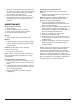
Installing the Air Filter The metal Air Filter is installed into the threaded port of the cylinder head. 1. Thread the Air Filter into the Cylinder Head by turning the Air Filter clockwise. 2. Securely tighten the Air Filter in place with a wrench. (See Figure 4) Oil Fill Crankcase Oil Sight Glass Figure 2. Installing the Oil & Oil Breather Cap Figure 4.
Attaching an Air Hose Your Air Compressor is supplied with a 1/4" Quick Disconnect Air Chuck. Once you have correctly installed the Air Chuck (See Installing the Air Chuck on p.4) your compressor will be ready to accept air hoses equipped with 1/4" male air couplers. Note: Use only air hoses rated for use with 115psi air pressure or higher. To install an air hose, equipped with a 1/4" male coupler: 1. Pull back on Air Chuck outer sleeve to allow coupler to be fully inserted into Air Chuck. 2.
Changing the Air Compressor Oil Note: This compressor uses only SAE 5W-30 motor oil. 1. Remove the Oil Sight Glass by turning counterclockwise with wrench. Note: Oil will begin to drain as Oil Sight Glass is loosened. Place a funnel and oil pan in place BEFORE loosening Oil Sight Glass. 2. Once Oil Sight Glass is removed, tilt Air Compressor backwards to allow all of the oil to drain out of the crankcase. 3. Once oil is drained, replace Oil Sight Glass and securely tighten in place with a wrench.
TROUBLESHOOTING TROUBLE POSSIBLE CAUSE CORRECTIVE ACTION Compressor Won't Start 1. Blown Fuse or Circuit Breaker Tripped 2. Loose Electrical Connections 1. Replace or Reset Fuse/Circuit Breaker 2. Check Wiring Connections Low Pressure 1. Restricted Air Filter 2. Defective Check Valve 3. Air Leak in Safety Valve 1. Replace Air Filter 2. Replace Check Valve 3. Check valve by pulling on ring. If condition persists, replace valve. Safety Valve Releasing 1. Defective Pressure Switch 1.
PARTS LIST AND DIAGRAM Part No. 01 02 03 04 05 06 07 08 09 10 11 12 13 14 15 16 17 18 19 20 21 22 23 24 25 26 27 28 29 30 31 32 33 Description Part No.
9