Northstar 2 kW Radar Installation Manual 1
FCC Statement Note: This equipment has been tested and found to comply with the limits for a Class B digital device, pursuant to Part 15 of the FCC Rules. These limits are designed to provide reasonable protection against harmful interference in a normal installation. This equipment generates, uses and can radiate radio frequency energy and, if not installed and used in accordance with the instructions, may cause harmful interference to radio communications.
Warranty The Northstar Warranty Statement is supplied as a separate document. It is shipped with the Product Registration Card. In case of any queries, refer to www.northstarnav.com. Feedback from you Your feedback is important and helps Northstar ensure that this manual is a valuable resource for all marine technicians. E-mail your comments or suggestions about this manual to the following address: manuals@northstarnav.com.
Contents FCC Statement....................................................................................................................................................................................... 2 Industry Canada.................................................................................................................................................................................... 2 Compliance Statement......................................................................................
6.2 6.3 6.3.1 6.4 6.4.1 6.4.2 6.4.3 6.4.4 6.4.5 6.4.6 6.5 6.6 6.6.1 Configure the navigator communications......................................................................................................................39 Heading sensor requirements .............................................................................................................................................39 Disable the heading sensor input ...............................................................................
1 Preface This manual explains how to install the scanner and the radar processor. It also explains how to set up the radar system after installation and gives information on troubleshooting. This manual is supplementary to Revision C and Revision D of the Northstar 6100i Networked Navigation System Installation Manual Part Number GM6KIM.
Only qualified personnel should install or service this equipment. Installation or servicing work that is done by non-qualified personnel can result in equipment breakdown, poor performance of the equipment, fire, electrical and physical hazards, injury or death. Wear safety equipment such as a hard hat and a safety belt at all times when installing or working on the scanner.
2 Introduction to the Northstar radar The Northstar radars are designed as an option available to the Northstar 6000i, 6100i, or 8000i systems. A variety of scanner models are available (2 kW, 4 kW, 6 kW, 10 kW and 25 kW) to suit different customer requirements. Each scanner model has a corresponding radar processor model. 2.1 2 kW radar system overview The 2 kW radar system is intended for use in a marine environment.
2.2 Check the 2 kW radar parts The RDR1021MD 2 kW radar system consists of a scanner, a radar processor, and associated cables. There are two basic options for the 2 kW radar: NS004790R is the standard 2 kW radar system, consisting of a box containing the scanner and the 49 ft (15 m) interconnection cable (NS003100). This is pre-installed into the scanner. NS004790M is the alternative 2 kW radar system, consisting of a box containing only the scanner.
NS004790M 2 kW scanner standard components Quantity Part name Part no. 1 Item Scanner unit NS004790 4 Hexagonal bolt 5/16-18 UNCx31.75 mm Part of Hardware kit HR000066 4 M8 Spring washer Part of Hardware kit HR000066 4 M8 Plain washer Part of Hardware kit HR000066 4 Rubber washer Part of Hardware kit HR000066 1 Packing list LA000450A 1 Installation sheet LA000410A MTZ303386 1 Mounting template LA000451A Part name Part no.
1 Product CD000085A Registration Card 1 Warranty CD000260A 1 Spare 3 A fuse HR000063 4 Mounting screw HR000061 NS003101 Optional longer length interconnection cable for radar scanner - order separately Quantity Item 1 Part name Part No Interconnection cable for the radar scanner NS003101 length 65.5 ft (20 m) Part name Part no. NS00481X cable for 8000i installation only - order separately Quantity Item NS004810 length Network cable 1.6 ft (0.
NS003108 Optional extension cable for 6000i and 6100i installations only - order separately Quantity 1 12 Item Part name Part no. NS003108 Radar communications extension cable for 6000i and 6100i installation ONLY.
3 Install the radar A radar unit should only be installed by a qualified marine technician, as potentially lethal high voltage is present along with heavy rotating parts. There is a transmit interlock that prevents radar transmissions if the scanner is not rotating. However, a high voltage remains for a period of time after the system is turned off.
DON'T DO THIS! DON'T install the scanner too high up, where its weight will alter the stability of the vessel and cause degradation of the radar picture over short ranges (see "How to find the optimum height for the scanner"). DON'T install the scanner close to lamps or exhaust outlets. The heat emissions may cause the equipment to breakdown and soot and smoke will degrade the performance of the radar.
However, when the power boat is traveling at high speed, the bow rises up out of the water and if the elevation angle (trim) of the bow is raised up so that it equals, or exceeds, 50% of the vertical beam width of the radar, this can cause two problems: ahead of the power boat, the beam is projected too high to sweep the water surface effectively. Targets can be missed completely or appear at a very poor resolution on the display screen.
3.2 How to find the optimum height for the scanner The optimum height for the scanner is as close as possible to the A-B line for best performance. How to find the A-B Line: The vertical extent of the radar beam is 2θ°, so most of the radar beam is concentrated within this angle, meaning that outside of this angle the radar beam will be very weak. Scanner model θ° value (half the -3 dB beam width) 2 kW 4 kW 6 kW 10 kW 25 kW 15 12.5 10 10 10 An example of an A-B Line is shown in the picture.
D is distance traveled by the radar beam h1 is the height above sea level of the scanner h2 is the height above sea level of a target An example is shown below: In this example, the scanner is installed on the vessel at a height of 10 ft (3 m) above sea level (h1). Island A is 33 ft (10 m) high (h2) and for comparison, Island B is 16.4 ft (5 m) high (h2). Both islands are at a distance (D) of 10 nautical miles from the vessel.
3.5 2 kW scanner dimensions Before starting the installation, use the drilling template to identify the: cable inlet drill holes front and rear of the radome location of the drain hole (ensure that your chosen location allows the drain hole to empty). The 2 kW scanner dimensions are shown: 3.
Orient the trestle so that the cable inlet on the scanner will face the stern, and so that the scanner can be mounted at the correct angle (as discussed in the "Power boat installation" section). Make sure that the edges of the trestle won't trap water. 3.7 Install the 2 kW scanner unit IMPORTANT: Remember that you must screw the bolts into place from the underside of the location site, because the shape of the dome prevents you from installing the bolts from the topside.
3.8 Install the radar processor Install the radar processor in a dry location away from spray, rain, drips, and condensation. The location site must allow you to easily connect the radar processor to the ship's ground, the interconnection cable, the power cable, and the 6000i and 6100i radar communications cable or the 8000i network cable. Check that these cables and the ship's ground can easily reach the radar processor BEFORE you drill. The radar processor dimensions are shown on the drilling template.
4 Wire the radar system Always install a separate circuit breaker or separate fuse for the radar system circuit. 4.1 Wiring guidelines Most installation problems are caused by shortcuts taken with system cables. When wiring the radar: DON'T make sharp bends in the cables. DON'T run cables in a way that allows water to flow down into the connectors. DO make drip and service loops. DO use cable ties to keep the cables tidy and secure.
Unscrew and remove the cover of the scanner, lifting it vertically to avoid bumping it against the antenna. Carefully lift the main unit and stand it upright in the slot on the scanner casing: Remove the shield cover from the underside of the main unit to expose the J connector locations and ground terminal location. The broken line shows the route for the interconnection cable.
Identify the connector ends B, C, and D on the 2 kW interconnection cable (NS003101). Connector D is an Earthing strap. Place the locking nut, gasket A and gasket B over the end of the interconnection cable in the order shown, then push the interconnection cable through the cable entry point into the radome. (Ensure that you push through sufficient cable to easily connect the J connectors.) At the cable entry point, take care that the grooves in gaskets A and B are opposite each other (see the figure).
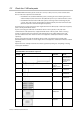
The wiring details for the connector ends (B, C, and D) are as follows: 2 kW interconnection cable (NS003101) connector ends 24 Pin Color AWG size B C 1 Green (big) #12 1 2 Yellow (big) #12 2 3 Green (thin) #24 7 4 Clear Coax signal #24 4 5 Drain wire for 4 #24 5 6 Drain wire for 7 #24 3 7 Black Coax signal #24 2 8 White #24 6 9 Yellow #24 1 10 White (big) #12 Shell Braid shield D 3 X Northstar 2 kW Radar Installation Manual
4.3 Run the 2 kW interconnection cable (NS003100/NS003101) to the radar processor Run the 2 kW interconnection cable (NS003100/NS003101) from the scanner to the radar processor. Push the round connector (A) of the 2 kW interconnection cable into the scanner connection on the radar processor and tighten the locking nut. The interconnection cable pin details are provided here for information, in case the connector needs to be removed to feed the cable, or in case the cable needs to be shortened.
4.4 2 kW radar processor connections There are four interface connectors on the rear of the 2 kW radar processor, plus a Chassis Earth. You can connect the radar processor to either the Northstar 6000i or 6100i OR to the Northstar 8000i, but not to both simultaneously. 2 kW radar processor interface connectors Connector name Connector function Network Ethernet communications for the 8000i Power input Power (+ve and -ve) NMEA / Comms Scanner Chassis earth 26 Connects to...
4.
4.5.1 Item Function A B C D E F G H I J K L M N 0 P Junction box To NMEA Device 1 To NMEA Device 2 To Smartcraft Remote power Circuit breaker/fuse box Optional radar communications extension cable (NS003108) Vessel's Ground NTSC Video Input Fuse (7A) GPS antenna Power NMEA Ethernet AUX VGA (out) Connect the radar communications cable (NS003107) to the junction box The free ends of the radar communications cable (NS003107) must be terminated in a junction box (see the figure in the previous section).
Wire function Free end Connector 1 6000i/6100i NMEA Connector 2 NMEA/Comms Connector 3 Smartcraft Pin Color Pin Color Pin Color NMEA 1 IN A Brown 3 Brown NMEA 1 IN B Blue 1 Blue NMEA 1 IN GROUND White/Blue 4 White/Blue NMEA 1 OUT A Violet 12 Violet NMEA 1 OUT B Gray 7 Gray NMEA 1 OUT GROUND Blue/White 8 Blue/White NMEA 2 IN A White/Brown 6* White/Brown 1 Green NMEA 2 IN B Brown/White 2* Brown/White 2 Red NMEA 2 IN GROUND White 5* White NMEA 2 OUT A Yellow
Connector 2 - Radar NMEA/Communications pin assignments Connector 3 - SmartCraft pin assignments 4.5.2 Configure the remote power control for a 6000i or 6100i (common power source) IMPORTANT: This remote power control option works correctly only when the 6000i or 6100i and the radar processor share the same power earth and are located 16.5 ft (5 m) or less apart.
where: Key Component A B Radar processor NMEA/Comms port C D E F G NMEA port Link in the junction box Fuse/Breaker board Fuse Battery The radar processor has two remote power inputs with opposite active states which are OR’ed together. Pin 10 input (active low) is used by the 6000i or 6100i systems and Pin 12 input (active high) is used by the 8000i system. Pin 12 is tied to ground through the NS003107 cable, to allow control through Pin 10.
4.5.3 Configure the remote power control for a 6000i or 6100i (different power sources) When the 6000i or 6100i and the radar processor have isolated power supplies, or are located more than 16.
4.6 Connect the 2 kW radar processor to an 8000i display You are recommended to use the following configuration when connecting the radar processor to an 8000i display, where: A is the (optional) NMEA Compass B is the Circuit breaker/Fuse box C is the vessel's Ground Alternative 8000i system configurations are possible. For further information please refer to the Northstar 8000i System installation documentation. 4.6.
Alternatively, if you want the radar to be powered ON only when vessel's engines are running, Pin 12 (active high) must be driven by the vessel's ignition key. 4.6.2 Connect an 8000i network cable (NS00481X) Connect the 8000i network cable (NS00481X) ONLY if you're connecting the radar system to a Northstar 8000i system. Push one end of the 8000i network cable into the NETWORK connector on the radar processor. Plug the other end into the network connector on the network linker.
Scanner Fuse/Circuit breaker Maximum length of rating power cable Power cable size 2 kW 4 kW 6 kW 10 kW 25 kW 5A 10 A 10 A 15 A 15 A 33 ft (10 m) 26 ft (8 m) 26 ft (8 m) 26 ft (8 m) 26 ft (8 m) 14 AWG 14 AWG 14 AWG 12 AWG 12 AWG Typically the fuse /breaker would be located in a fuse/breaker box with the fuses/breakers for other devices. The radar processor must have it's own exclusive fuse/circuit breaker. The fuse/circuit breaker should be labeled appropriately.
4.9 Radar system checklist When you've finished the wiring, visually check that: each component is securely mounted and able to withstand rough sea conditions. all the cables are correctly installed. any cable shield mesh is correctly configured. all cable entry points are watertight. water can't leak into the scanner. Now you're ready to set up the radar with the Northstar system that you're using.
5 Set up the radar with a Northstar system Setting up the radar with: the Northstar 6000i or 6100i system is described in the following section. the Northstar 8000i is described in the Northstar 8000i System installation documentation for your display processor. a different Northstar system is described in that system's documentation.
6 Set up the radar with the Northstar 6000i or 6100i 6.1 Turn the radar on and off 6.1.1 Before you turn on the radar for the first time To extend magnetron lifetime, you're recommended to leave the radar in Standby mode for 30 minutes when activating the radar for the VERY FIRST time. (When the radar is in Standby mode, it's NOT transmitting but it is powered up – this allows the magnetron heater to stabilize). Then, after 30 minutes, press the RADAR ON key to test and align.
6.2 Configure the navigator communications IMPORTANT: If you are going to operate the radar without a heading sensor, ignore this section and set up the radar as described in "Disable the header sensor input". To enable the radar to communicate with the navigator, set up the radar option on the navigator's PORT 2 SETUP screen as follows: 1. Press STAR several times to display the OPTIONS/SERVICE INFO screen. 2. Press Port Setup Options. 3.
6.4 Calibrating the radar You must calibrate the newly installed radar by adjusting the trigger delay and the heading calibration. To evaluate medium and short range returns, you are recommended to perform the calibration at sea in a normal operating environment and under fair weather conditions. There should be an area of at least 3 nautical miles forward of the vessel, containing known targets including the coastline.
2. Press Page 2, Page 3, Page 4 then Install... and then Tune... . 3. Press STC Curve then use the keypad to enter a curve number from 0 to 8. 6.4.4 Set the trigger delay There are two methods that you can use to set the trigger delay. The two methods should produce very similar settings. Method 1 is easier to perform but Method 2 may produce more accurate results. You can use either, or both, methods.
IMPORTANT: Make sure the heading sensor is calibrated according to the manufacturer's recommendations. 1. When performing a sea trial of the vessel, set a straight course for a solid object such as a lighthouse, jetty or radar navigation marker that is at least 1 nautical mile distant as referenced on the chart. 2. Press CHART to display the chart then press Overlay to show the radar echoes overlain on the chart. 3.
ranges, and the Range Rider will store these settings for each range. Then, when you select a particular range again, the settings are already optimized. Manual is a fully manual function in which you will usually need to adjust the settings manually each time you change the range. Gain and Sea Clutter appearance settings are available in Auto1, Auto 2 and Harbor modes.
7 Maintenance Before doing any maintenance work, always ensure that the radar system is turned OFF at the main power source. If a rectifier unit is used, turn OFF the power supply to this too. Remember that high voltages from the rectifier unit are always present, even if the radar is not operating, and these can cause severe injury or death. 7.1 General maintenance Proper maintenance of the radar system will keep it in good condition and minimize breakdowns. Periodically: 7.
8 Troubleshoot the radar This appendix gives information on fixing possible problems with the radar. Many problems are caused by: faulty or loose contacts at switches and relay points poor adjustment of the radar (particularly inadequate tuning adjustment) poor maintenance (particularly of the cables) You'll save yourself a considerable amount of time if you check these items before placing a call to Northstar; plus, you may find the problem right away. 8.
If an image appears on the display but the direction of the radar image is not stable: 8.3 the direction standard signal (BZ) is being interrupted (see the Service Manual) check for water damage to the radiator or cables between the radar components. If the scanner fails to turn If the scanner fails to turn, it is possible that there has been a breakdown of either the motor unit inside the scanner or the safety switch of the scanner unit. Turn the power OFF and investigate as follows: 1.
8.5 Make sure the power is present and correctly wired Check the in-line fuse. Re-verify that the correct system voltage is being used for the radar processor box model and that the power is properly wired. If the radar processor has incorrect power, the system may not initialize properly or the radar processor may be damaged. 8.6 Confirm the equipment installed 1. Confirm the type of navigator used with the radar (6000i, etc).
9 Manual tuning procedure for the 6000i or 6100i system NOTE: The following manual tuning procedure is provided only for possible situations where the unit's automatic tuning does not perform well with a Northstar 6000i or 6100i system. At present, Northstar is not aware of any such situation and recommends that automatic tuning be used, unless a reason is found to use this manual procedure.
10 2 kW radar system specifications 2 kW scanner DC input 10.8 V to 15.6 V DC (DC 12 V system ONLY) Scanner type Scanner dimensions Radome Depth: 17.7" (450 mm) Height: 8.93 (227 mm) 9.26 lbs (4.2 kg) ± 5% 0.1" (3 mm) (0 to 500 cpm) 0.29" (0.75 mm) (550 to 1500 cpm) 0.007" (0.2 mm) (1500 to 3000 cpm) IPX6 Horizontal Minimum 90 seconds 25 W (maximum) at 12 V DC P0N FCC ID: CKEJMA1020 IC ID: 768381105A R&TTE: DERA-RTTE-34/01-01 2 kW ±50% under any pulse conditions 9445 ±30 MHz Magnetron NJRC M1537 5.
2 kW Radar processor specifications Radar system Processor model Processor dimensions Processer weight Vibration Waterproof Temperature range Relative humidity Power up time DC input Power consumption NS-RDR-1021MD NS004780 Width 5.6" (142 mm) Height 2.2" (56 mm) Length 7.9" (200 mm) 1.9 lbs (870 g) EN60945 No rating +5ºF to +131ºF (–15ºC to +55ºC) 95% at 104ºF (+40ºC) Approximately 35 seconds 10.
2 Northstar 2 kW Radar Installation Manual