M157115D ITEM NUMBER: 157115 SERIAL NUMBER: _____________ Owner’s Manual Instructions for Set-up, Operation, Maintenance & Storage HOT WATER/STEAM PRESSURE WASHER – 3000 PSI / 4.0 GPM Portable Outdoor-Use Only This pressure washer produces both cold and hot water high-pressure spray as well as wet steam. Cleaning chemicals may be incorporated into the spray if desired.
Hazard Signal Word Definitions Equipment Protection Quick Facts STOP! Closely inspect to make sure no components are missing or damaged. See the Inspect Upon “Assembly and Initial Set-Up” section for instructions on whom to contact to report missing or Delivery damaged parts. STOP! Engine is shipped without oil. DO NOT start pressure washer without adding oil to Fill with engine. Please refer to Engine Manual shipped with unit for acceptable grade motor oils.
Table of Contents About Your Pressure Washer ..................................................................................................................... 4 Specifications ................................................................................................................................................. 5 Component Identification ............................................................................................................................. 6 Safety Labeling ...............
About Your Pressure Washer Thank you for purchasing a NorthStar hot water pressure washer! Your machine is designed for long life, dependability, and the top performance you demand. This pressure washer is designed to: 1) Produce a high-pressure wet steam spray or water spray (heated or unheated) -- up to 4.0 gallons per minute at 3000 psi. 2) Incorporate cleaning chemicals into a low-pressure water spray. Wet steam is a combination of liquid water droplets and water vapor.
Specifications MODEL Model # 157115 FLOW OUTPUT Pressure Rating 3000 psi Flow Rate 4.0 gpm Maximum Temperature 250 F DIMENSIONS / COMPONENTS Length 46” Width 32” Height 43” Weight (fueled) 457 lbs.
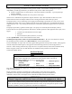
Component Identification 9 13 SEE DETAIL B 3 20 22 DETAIL B 11 1 26 5 8 SEE DETAIL D 18 19 7 6 2 12 25 SEE DETAIL A 17 21 4 DETAIL A DETAIL D DETAIL C PRESSURE WASHER PUMP 10 BURNER FUEL PUMP SEE DETAIL C ASSEMBLY, PUMP MOUNT FAN, FLYWHEEL, & STATOR ASSEMBLY 24 FUEL PUMP SHEAVE BELT, MICRO-V J 4 RIB X 36" 16 15 23 AIR, FUEL, IGNITION SYSTEM Fig157115_1 Ref # 1 2 3 4 5 6 7 8 9 Description High PSI limit switch Flow Switch Heating Coil Garden Hose Water Inlet Pump Diesel Fuel T
Component Identification cont’d REFERENCE GUIDE 1. High, PSI limit switch This is a backup safety feature, if the system pressure exceeds the set pressure this device will stop the burner from firing. 2. Flow Switch Mechanical device that senses water flow 3. Heating Coil 4. Garden Hose Water Inlet 5. Pump Steel piping wound together with an inlet for incoming cold water and outlet for hot water to exit. Means of connecting garden hose to pump inlet. Connect garden hose here.
Safety Labeling 5 5 1 1 4 4 2 7 5 1 5 6 4 6 3.1 3 1 4 2 3.1 VIEW ROTATED FOR CLARITY 6 7 2 3 2 VIEW ROTATED FOR CLARITY 3.1 6 Fig157115_3 3 VIEW ROTATED FOR CLARITY 3.1 3 VIEW ROTATED FOR CLARITY Always make sure safety labels are in place and in good condition. If a safety label is missing or not legible, order new labels or unsafe operation could result. To order replacement safety labels, call NorthStar Product Support at 1-800-270-0810. Ref.# Part # Description Qty.
Special Equipment Safety Features High Pressure Safety Device (Rupture Disc) WARNING: If the high-pressure safety device ever discharges water, turn the engine off and do not use the machine. Call Product Support at 1-800-270-0810. This unit is equipped with a high-pressure safety feature. If the unloader malfunctions the high-pressure safety device will open and relieve excess system pressure.
Assembly and Initial Set-Up STEPS FOR ASSEMBLY / INITIAL SET-UP STEP 1. UNPACKING & DELIVERY INSPECTION STEP 2. ASSEMBLY STEP 3. INITIAL PUMP & ENGINE PREPARATION Each of these steps is discussed below: STEP 1. UNPACKING & DELIVERY INSPECTION Find and separate the components identified in Fig157115_4 – Unpacking, delivery, inspection, assembly and initial set-up and Fig06833 – Hardware Bag. Inspect the pressure washer immediately after you receive delivery for missing parts and damage.
Assembly and Initial Set-Up M8-1.
Assembly and Initial Set-Up STEP 2. ASSEMBLY You must assemble your pressure washer before it can be used. Refer to Fig157115_6 and follow the steps listed below: INSTALL NOZZLES INTO DESIGNATED NOZZLE STORAGE LOCATION INSTALL HOSE HOOK INTO RIGHT SIDE OF HANDLE USING TWO (2) M8-1.25 NYLOC NUTS 5/16-18 X 3/4" SIX (6) FLANGE BOLTS 5/16-18 X 3/4" SIX (6) FLANGE NUTS Fig157115_6 Step 1.
Assembly and Initial Set-Up STEP 3. INITIAL PUMP & ENGINE PREPARATION Prepare Water Pump Verify pump oil level. Note: The pump is shipped with oil. 1. Remove shipping tape and black vent plug (if present) from oil fill cap. 2. Verify that oil level is halfway up the sight glass. OIL CAP OIL SIGHT GLASS PLUG Fig157115_14 DRAIN HOSE 3. If oil level is low, fill using SAE 30 non-detergent oil or Cat Pump Oil Item # 22158. Prepare Engine Fill the engine with oil. Note: The engine is shipped without oil.
Moving and Handling WARNING The pressures washer is heavy. It can crush and cause serious injury if it rolls out of control or tips over. Follow the instructions below for safely moving the pressure washer. MOVING AND HANDLING HANDLE Fig157115_6 Moving your pressure washer around 1. Use the handle to manually move the pressure washer. 2. To turn, push down slightly on the handle and pivot the pressure washer on its back wheels. 3. Lock wheels with brake to prevent inadvertent movement.
Before Each Use Follow the steps below prior to each use of the pressure washer. STEPS TO FOLLOW BEFORE EACH USE STEP 1. CHECK EQUIPMENT STEP 2. ADD FUEL(S) STEP 3. SELECT SUITABLE WORKSITE STEP 1. CHECK EQUIPMENT Check/add pump oil Check/add pump oil. Caution: Never run the pump without sufficient lubrication! 1. Check oil level. Verify that oil level is halfway up the sight glass. Remove shipping tape and black vent plug (if present) from oil fill cap. 2.
Before Each Use looseness, or leaks. Replace as required. 2) Check and clean the nozzle orifice. 3) Clean inlet filter. (See Maintenance instructions) Inspect fuel system Always inspect (engine and burner) fuel systems & check for leaks BEFORE starting pressure washer. Do not start pressure washer until all needed repairs have been completed. WARNING: Fuel leak hazard Gasoline and burner fuels are highly explosive and fuel leaks can result in fire or explosions.
Before Each Use explosion can result. 3) Stay away from all sources of heat, sparks, and flames. Do not smoke. 4) Never pump fuel directly into the gas tank or burner at a gas station – it could cause a static electric spark. Follow these steps to avoid static electric sparking during fueling: • • • • Use an approved portable container to transfer fuel to the pressure washer’s tank. (A portable container made of metal or conductive plastic is preferred because it dissipates charge to ground more readily.
Before Each Use STEP 3. SELECT SUITABLE OUTDOOR WORKSITE Before using the pressure washer, you must understand the criteria for selecting a suitable location for operation. Note that this pressure washer is for OUTDOOR USE only. WARNING: You must choose a suitable site for operating your pressure washer to avoid equipment damage and/or injury and possible death from carbon monoxide poisoning, fire/explosion, uncontrolled equipment movement/tip over, or slips and falls.
Before Each Use 2. Away from combustible dust, liquids, or vapors Do not locate and use the pressure washer in the presence of flammable vapors, dust, gases, or other potentially combustible materials. Burner is an open flame, which can ignite airborne dusts and flammable vapors. Operate only where open flame or torch is permitted. 3. Adequate ventilation airflow The pressure washer needs adequate, unobstructed flow of air to allow for proper combustion and adequate cooling.
Operation After you have checked and fueled the equipment and positioned it in a suitable worksite, it is time to start your pressure washer. The following are the procedures necessary for safe, successful operation of your pressure washer. WARNING Carefully read and make sure you understand all instructions and safety information before using the pressure washer.
Operation Attach garden hose to water supply Acquire a suitable garden hose and attach to the water supply. Check water supply Check adequacy of water supply. Water supply should be standard tap water. 1. Acquire a suitable garden hose: a. The water supply garden hose must have an inside diameter of at least 5/8”. If the hose is more than 100 ft. long, the diameter must be at least 3/4”. b. Always use a flexible rubber hose for your water supply. Do not use rigid piping. c.
Operation 3. Release the collar, making sure it springs back and re-seats to its original (nonretracted) position. (Fig. 8b). Check the connection by pulling on the hose to ensure a positive connection. Select spray nozzle Correct Insertion Not Fully Inserted Collar Seated Collar NOT Seated Fig. 8b Your pressure washer is equipped with four high-pressure nozzles and one steam nozzle. Generally, the wider the spray angle of the nozzle, the lower the spray impact produced.
Operation Lance Coupler Nozzle Collar Fig. 9a 3. Release the collar, making sure it springs back and re-seats to its original (nonretracted) position. (Fig. 9b). Check the connection by pulling on the nozzle to ensure a tight connection -- if correctly inserted, nozzle will rotate but not pull out. WARNING: Make sure the nozzle is correctly inserted. Sprayer nozzle can become a projectile and cause serious personal injury or property damage if not properly connected to the spray gun.
Operation • It mixes the cleaning chemical into a low-pressure spray. Cleaning chemicals applied under low pressure adhere better to the surface being cleaned, allowing the formula time to react and remove dirt more effectively. Note: An external chemical injector pump is not recommended for use with this pressure washer, and if used would obviously alter the 15 to 1 dilution ratio. WARNING: Chemical spraying • Never spray acids, corrosives, or abrasive or flammable liquids.
Operation Instruct all operators. The pressure washer’s owner must instruct all operators and potential renters in safe set-up and operation. Do not allow anyone to operate the pressure washer who has not read the Owner’s Manual and been instructed on its safe use. Adult control only. Only trained adults should set up and operate the pressure washer. Do not let children operate.
Operation be a small puncture wound that does not look serious. However, severe infection or reaction can result if proper medical treatment is not administered immediately by a doctor who is familiar with injection injuries. Seek medical aid for suspected carbon monoxide poisoning. The running engine gives off carbon monoxide, a poisonous gas that can kill you. If you start to feel sick, dizzy, or weak while using the pressure washer, shut off the engine and get to fresh air RIGHT AWAY. See a doctor.
Operation 3. Follow the instructions in the Engine Manual for starting the engine. DANGER: Do not inhale engine exhaust. It contains dangerous carbon monoxide that can kill you. Apply cleaning chemical (if desired) Turn on burner (If hot spray or steam is desired) If desired, spray cleaning chemical at low pressure (with or without heated water). 1. Make sure the chemical injector is properly set up according to the instructions in Step 2, “Set Up for Chemical Spraying”. 2.
Operation • NEVER attempt to immediately run or re-light the burner if it does not ignite the first time. Unburned fuel or gas in burner may have accumulated, causing potential explosion or fire hazard. • Do not attempt to set temperature limit above the preset limit. • Never touch hot burner surfaces and stay clear of burner exhaust. All are extremely hot and will burn you. • Do not inhale burner exhaust. It contains dangerous carbon monoxide that can kill you. 4.
Operation addition, high-pressure spray will dislodge unsecured objects as well as surface chips and debris, resulting in hazardous flying objects that can cause personal injury or property damage. Do not spray brittle surfaces or breakable, fragile, or unsecured objects such as: o stucco or laminar flagstone o some painted surfaces o windows or glass doors (because they may break) o light fixtures, flowerbeds, mailboxes o unsecured, lightweight objects Procedure: 1.
Operation UNLOADER Fig157115_8 9. If temporarily interrupting spraying, rotate trigger safety latch downward to the locked position to guard against accidental trigger release. 10. Always turn off the engine and activate spray gun trigger to relieve system pressure when: • the sprayer is unattended, or • disconnecting hoses, installing/cleaning nozzles, or servicing the pump. WARNING: Always turn off the engine and relieve system pressure when finished spraying or when leaving sprayer unattended.
Storage STORAGE When you are finished using the pressure washer, you must prepare the sprayer for storage and store it in a proper location. Note: o o If you will be storing the sprayer in freezing conditions, follow the instructions for preparing the sprayer for storage in freezing conditions. If you will not be using the sprayer again for 30 days or more, follow the instructions for preparing the engine for long-term storage. WARNING • Fuel and its vapors can ignite and cause a fire.
Storage RV Antifreeze Supply Bucket Hose Fig. 06841_1 Spray Bucket Materials list: 1) Two 5 gallon buckets 2) 4-5 foot long garden hose or equivalent (recommend 5/8” to ¾” diameter with male ¾” Garden hose threads on one end) Procedure: 1) In a 5 gallon pour at least 2 gallons of environmentally safe antifreeze. Note: whether using undiluted or pre-diluted antifreeze, follow manufactures mixing guidelines to ensure proper freeze protection. 2) Elevate bucket so it is higher than the unloader.
Storage Alternately the system can be blown out with compressed air: Note: although this method can be effective for winterizing, the above antifreeze method is preferred because it ensures the entire plumbing system is flushed and lubricated. Materials: 1) Properly rated fittings (80 psi or higher) to connect air supply to inlet connection (¾” garden hose) on pressure washer. 2) Air compressor with regulator able to set pressure between 60-80 psi. Procedure: 1) Connect hose and gun to outlet connection.
Storage 2. Lubricate cylinder and piston: a. Disconnect spark plug wire and remove spark plug b. Add one teaspoon oil through spark plug hole c. Place rag over spark plug hole and turn starter (or pull the recoil) a few times to lubricate the combustion chamber. d. Replace spark plug, but do not reconnect the spark plug wire. Prepare pressure washer for storage Prepare the pressure washer for storage. 1. Make sure the engine start switch is OFF and fuel valve is OFF. 2.
Burner Adjustment OIL BURNER ADJUSTMENT (ONLY NEEDED IF WHITE EXHAUST SMOKE APPEARS) The oil burner is preset, and performance tested at the factory (elevation 1100 feet). Different altitudes may require a one-time initial burner adjustment. CAUTION: If white smoke appears from the burner exhaust vent during start-up or operation, discontinue use and readjust air bands. Specific steps for burner correction are given below.
Maintenance & Repair Inspect and maintain your pressure washer as specified below in order to keep it in safe and optimal working order. Follow all safety rules and recommended maintenance instructions. WARNING ALWAYS shut off water supply, bleed water pressure, turn off engine and disconnect the spark plug before cleaning, adjusting, or servicing the pressure washer. After servicing, make sure all guards and cover shields are replaced before using.
Maintenance & Repair MAINTENANCE & REPAIR-DETAILED INSTRUCTIONS Follow safety rules Read and follow these safety rules whenever you will be servicing the pressure washer: • Turn off / relieve pressure first. Always turn off pressure washer and relieve system pressure before inspection or maintenance. Remove spark plug or spark plug wire to prevent accidental starting. • Fuel valve off. Turn fuel shut-off valve to OFF position before transporting or servicing the pressure washer. • Replace guards.
Maintenance & Repair High-pressure fluid discharge from leaks (even pin-sized) or ruptured components can pierce skin and inject fluid into the body. Injection injury can result in blood poisoning and/or severe tissue damage leading to infection, gangrene, and possibly amputation. • Never use a finger or skin to check for leaks. • Never operate machine with damaged or missing hoses/parts.
Maintenance & Repair Perform engine maintenance Perform engine maintenance as specified in the engine owner’s manual. Engine maintenance items include: 1. Changing oil and oil filter 2. Air filter check/replacement 3. Spark plug cleaning and replacement 4. Fuel filter check/replacement 5. Inspecting and cleaning muffler (and spark arrestor if equipped) Change pump oil Change the pump oil after the first 40 hours of use, and then after every 3 months or 500 hours of use after that. 1. 2. 3. 4.
Maintenance & Repair Maintain burner’s fuel filter/water separator Drain water from burner’s filter bowl as needed and replace filter after every 500 hours of use or as needed. 1) After each use of the burner, visually check the filter bowl. If any water has accumulated, drain it via the water drain at the bottom of the bowl. 2) After every 500 hours of operation, empty the burner’s fuel tank in order to remove the filter bowl and inspect the fuel filter/water separator. Replace filter as needed.
Maintenance & Repair WARNING SCALE BUILD-UP/EXPLOSION HAZARD • Failure to properly maintain the coil can result in a steam explosion. • Scale or lime build-up will act as an insulator and decrease coil efficiency. • Weakening of the coil tube due to hot spots can result in a coil rupture. CHEMICAL EXPOSURE HAZARD • Always wear properly rated safety goggles when descaling the coil. • Always wear rubber gloves when handling coil cleaning chemical.
Maintenance & Repair 10) Dispose of the cleaning solution where it is not harmful to animals or the environment. Follow the coil cleaner manufacturers disposal instructions. 11) Fill the 5-gallon bucket with fresh water. 12) Place the end of Return Hose back into the 5-gallon bucket with fresh water. 13) Place the end of Supply Hose B back into the 5-gallon bucket with fresh water. 14) Turn on the circulating pump to begin circulating the fresh water.
Maintenance & Repair Cleaning Flow Switch Inspect and clean the flow switch as needed Mineral build-up and/or debris within the flow switch can occur and may affect burner operation if not periodically cleaned. Mineral build-up and/or debris can stop the movement of the shuttle inside the flow switch body. Shuttle movement is important because the burner will not fire if the shuttle does not move.
Maintenance & Repair Shuttle Assembly (Side View) Magnet Assembly (Bottom View) 4) Observe the “Shuttle Assembly” and internal portion of “Body” for obstructions, hard water deposits and any other foreign debris. Remove the foreign debris with light scraping or compressed air. If no additional cleaning is required continue to Step 7. If additional cleaning is required continue to step 5.
Maintenance & Repair Body (female) Guides) Shuttle (Male) Tabs) Rounded End FIG03514 First FIG03514 9) Inspect the O-ring on the “Cap”, if it is damaged, replace the entire flow switch assembly. To order a replacement flow switch assembly, call Northstar Product Support at 1-800-270-0810. If the O-ring is not damaged, re-install the “Cap” onto the “Body”. Torque the cap to 100lb-in. Cap Fitting; Torque to 100lb-in 10) On the elbow on the inlet of the coil, remove any remaining thread tape/sealant.
Maintenance & Repair Inspect heating coil and desoot as needed Inspect and desoot coil annually. Most coils never require desooting. However, poor grades of fuel oil or inadequate combustion air will cause heavy soot build-up on the outside surface of the heating coil tubing. These deposits will insulate the coil, which then restricts air flow through the heat exchanger and further aggravates the soot build-up. Be sure to wipe the sight glass. See Outer Cover Fig06172 on next page.
Maintenance & Repair Inspect electrodes Inspect electrodes yearly and replace as needed. 1) Loosen front (2) bolts using a 1/2” socket. Loosen side (2) bolts using a 1/2” socket and wrench. 2) Remove (3) screws using a 5/32” hex key Allen wrench from the combustion head. Lift off combustion head from outer cover. FRONT BOLTS (2) SIDE BOLTS (2) Fig06843 Fig06842 3) Disconnect flame sensor and electrode wires. Disconnect fuel line.
Maintenance & Repair Instructions for inspecting: 1) Remove flame sensor bracket Flame sensor bracket Fig157115-4 2) Following normal starting procedure with burner and thermostat off. With unit running look through flame sensor sight glass to observe if there is a spark Ignition coil Instructions for setting Gap: 1) Disconnect engine spark plug wire. 2) Remove Belt guard. 3) Check gap between pickup arm and magnet to determine if adjustment is needed.
Maintenance & Repair BELT TENSION BRACKET MOUNT BOLTS FIG A FUEL PUMP MOUNT FUEL PUMP FIG B LOWER FUEL PUMP MOUNT BOLT TENSION BRACKET FIG 157114-11 TENSIONING NUT FIG C Note: • • • Some general rules of belt tension are: The ideal tension is the lowest tension without belt slippage Over tightening decreases belt and bearing life. Keep belts clean and free of foreign material that may cause slippage • Do not apply belt dressing, which can cause damage and early belt failure.
Maintenance & Repair NorthStar Product Support will assist in these repairs as needed, but if an inoperable pressure washer creates a major expense to your business, then we strongly recommend the following: • • Have a staff person become familiar with the mechanical operation of the pressure washer and capable of making minor repairs and performing all preventative maintenance procedures. Keep a stock of recommended service parts for maintenance and minor repairs.
Troubleshooting Causes Low Oil Shutdown Cold Engine No Fuel Spark plug wire not attached Causes Air ENGINE WILL NOT START Solutions Fill engine with the adequate amount of oil. Choke engine to start. Add gas to engine; make sure fuel shutoff valve is open. Attach spark plug wire to spark plug. PRESSURE WASHER RUNS BUT BURNER DOESN’T FIRE Solutions Belt for Air fuel delivery system is Replace or tighten belt.
Troubleshooting PRESSURE WASHER SURGES OR CYCLES WHILE IN BYPASS Causes Solutions Leak between unloader and gun. Check all connections between unloader and gun for leaks. Tighten loose components and replace damaged components. Gun leaking internally Replace spray gun. Causes Engine not at full throttle Damper not adjusted properly Poor quality fuel Belt broken Causes Scale build-up in coil Coil is full of soot SMOKE FROM HEAT EXCHANGER Solutions Throttle engine all the way up.
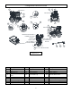
Major Components 5 4 2 3 1 Fig157115_11 MAJOR COMPONENTS Ref.# 1 2 3 4 5 Description Frame Heat Exchanger Blower and ignition flywheel Engine, Water pump, Fuel pump and drive parts Accessories- Gun, hose, chemical injector These components go into more detail on the following pages.
Parts Explosion: Frame – Rev D 34 47 14 22 21 46 47 27 6 18 4 49 9 10 20 34 5 39 8 7 2 35 1 11 19 37 48 38 33 23 40 2 43 25 26 45 3 27 28 29 42 24 31 30 12 13 36 44 41 32 17 15 16 Fig157115_12 54
Parts Explosion: Frame – Rev D ITEM PART# DESCRIPTION 1 2 3 4 5 799967 82008 800618 800619 788040 CORE WELDMENT NUT, 10-32 KEPS GROMMET, 1.25 ID-.
Parts Explosion: Frame – Rev D ITEM PART# DESCRIPTION 42 43 44 45 46 777646 799931 802972 82007 82631 LED, RED 12VDC RECTIFIER CONTROLLER, TEMP. ASSEMBLY SCREW, 10-32 X 3/4" SHCS NUT, 3/8-16 HEX FLANGE NYLON 2 1 1 1 1 47 82019 NUT, 5/16-18 SER.
Parts Explosion: Heat Exchanger – Rev D 1.1 1.2 1.3 1.25 1.4 1 1.26 1.5 1.24 1.27 1.23 1.15 1.22 1.16 1.6 1.8 1.7 1.17 1.21 1.9 1.18 1.31 2 21 1.10 1.20 1.11 1.28 1.12 1.19 1.13 1.30 13 1.14 20 3 1.32 12 1.33 4 22 14 23 15 16 17 5 6 7 9 18 19 Fig06846 57 24 11 8 1.
Parts Explosion: Blower & EMF – Rev D ITEM 1 1.1 1.2 1.3 1.4 1.5 1.6 1.7 1.8 1.9 1.10 1.11 1.12 1.13 1.14 1.15 1.16 1.17 1.18 1.19 1.20 1.21 1.22 1.22.1 1.22.2 1.23 1.24 1.25 1.26 1.27 1.28 1.29 1.30 1.31 1.32 1.
Parts Explosion: Blower & EMF – Rev D 1 12 9 4 7 11 8 10 2 5 13 3 20 19 17 Fig06847 16 6 21 18 14 15 ITEM PART# DESCRIPTION 1 2 3 4 5 6 N/A 82015 792268 799845 799693 82109 ASSEMBLY FAN & HUB STATOR 5/16-18 X 3/4 HHSF BOLT FAN, 200MM X 47.5MM - PW STATOR ADAPTER PLATE, DC HUB STATOR ASSY 3/8-16 X 3.
Parts Explosion: Blower & EMF – Rev D 5 21 2 17 19 11 16 15 22 18 20 Fig06875 ITEM PART# DESCRIPTION QTY SEE ABOVE TABLE 5 2 82015 5/16-18 X 3/4 HHSF BOLT 1 11 788016 2 MM SPACER 1 15 82004 16 802202 #8-32 x .
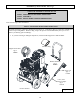
Parts Explosion: Engine, Water & Fuel Pumps, Drive Parts – Rev D 39 40 42 41 43 48 44 27 14 29 30 31 50 28 47 45 46 32 33 35 34 26 51 34 36 SEE DETAIL A 38 37 6 7 8 14 3 4 5 49 13 9 21 11 25 24 12 11 10 22 20 19 18 17 16 1 2 3 4 Fig157115_13 61 15 23
Parts Explosion: Engine, Water & Fuel Pumps, Drive Parts – Rev D ITEM PART# 1 6066 HC17210ZE3505 HC17218ZE3505 DESCRIPTION ENGINE, HONDA GX390 ELEMENT, AIR CLEANER FILTER, OUTER QTY 1 1 1 2 801096 FITTING MJIC-6 x 12MM 1 3 801089 HOSE, OIL DRAIN 2 4 801097 FITTING, 3/8" FPT CAP 1 5 799630 PUMP, 66DX CAT 4.
Parts Explosion: Engine, Water & Fuel Pumps, Drive Parts – Rev D ITEM PART# DESCRIPTION QTY 39 82622 BOLT, 5/16-18 x 1.5" HHFB 2 40 801636 ASSEMBLY, PUMP MOUNT 1 41 795015 MOTOR/PUMP COUPLER 1 42 792264 FUEL PUMP, 12V 1 42.1 RWB21754U FUEL SOLENOID COIL, 12V 1 42.2 RWB21877U FUEL SOLENOID STEM 1 43 777340 1/4"MPT X 1/4"HB 1 44 801448 FITTING, 1/4" HB X 1/4" NPT 1 45 801472 FITTING, 1/8" HEX NIPPLE 1 46 794146 FITTING, 1/4 JIC TO 1/8 NPT 45 DEG.
Parts Explosion: Accessories- Gun, Hose, Chemical Injector – Rev D 3 2 13 11 12 1 10 14 8 5 15 7 4 16 6 9 Fig157115-15 ITEM PART# 1 2 2.
Pump Explosion-CAT 66DX- Rev D REF# QTY REF# 5 8 9 10 11 13 15 20 25 27 32 33 37 38 40 48 49 50 51 53 64 65 PART# CA125824 CA46901 CA43222 CA14028 CA125351 CA14037 CA146421 CA48843 CA134878 CA14480 CA46798 CA14179 CA92241 CA44428 CA125824 CA25625 CA23170 CA48862 CA14048 CA48830 CA46404 CA48845 Screw, HHC (M6x16) Cover, Bearing Seal, Oil, Crankshaft O-Ring, Bearing Cover - 70D Seal, Oil, Crankshaft O-Ring, Bearing Cover Bearing, Ball - Inner Rod, Connecting Crankshaft 11.
Pump Explosion-CAT 66DX- Rev D REF# PART# DESCRIPTION QTY REF# PART# 401 402 403 404 408 410 412 414 415 418 423 424 425 426 CA49100 CA49099 CA125521 CA88953 CA45198 CA49101 — — — — CA49105 — — — Handle, Adjusting (Black) Cap, Adjusting Nut, Locking (M25x1) Screw, Set (M4x4) Spring, Pressure Retainer, Spring Stem, Piston Back-up-Ring, Piston Stem O-Ring, Piston Stem - 90D Assy, Piston (Included in Repair Kit) Retainer, Valve O-Ring, Valve Retainer - 70D Retainer, Piston Washer 1 1 1 1 1 1 1 1 1 1
Wiring Diagram – Rev C.
Summary of Important Safety Information This section provides a summary of the various safety procedures and measures that have been presented throughout the manual. Keep this summary handy and refer to it to refresh your memory about how to safely use your pressure washer. WARNING Carefully read and understand the following safety information before using the pressure washer.
Summary of Important Safety Information • • • • • ONLY use pressure washer outdoors and at least 20 feet from the home, away from windows, vents, and air intakes, to allow proper ventilation. If you start to feel sick, dizzy, or weak while using the pressure washer, shut off the engine and get to fresh air RIGHT AWAY. • NEVER run pressure washer in an enclosed or partially enclosed location such as a building, garage, shed, or vehicle.
Summary of Important Safety Information • Know how to stop. Be thoroughly familiar with proper use of the equipment and all controls and connections. Know how to stop the pressure washer and relieve system pressure quickly if needed. • Danger: High-pressure fluid injection hazard. High-pressure fluid spray or discharge from leaks (even pin-sized) or ruptured components can pierce the skin and inject fluid into the body.
Summary of Important Safety Information • • • • • • • • • • • • • • • Be aware of puddles and slippery surfaces. Ensure there is adequate drainage to prevent pooling of water. Keep spray away from people. Never direct discharge stream at or near any person. Do not allow any part of the body to come in contact with the fluid stream. High-pressure spray will cause serious skin, eye, or falling injuries, and hot water can burn.
Summary of Important Safety Information • Relieve water pressure. Always stop the product and relieve system pressure before leaving the sprayer unattended, or when disconnecting hoses, removing nozzles, or servicing the pump. • Refueling. Never add gasoline to the engine or fuel to the burner unless unit is off and has cooled. • Do not direct spray at this machine. Do not attempt to clean this machine with its own spray. Engine damage will result.
Limited Warranty Dear Valued Customer: The NorthStar Product you just purchased is built with the finest material and craftsmanship. Use this product properly and enjoy The benefits from its high performance. By purchasing a NorthStar product, you show a desire for quality and durability. Like all mechanical equipment this unit requires a due amount of care. Treat this unit like the high quality piece of machinery it is. Neglect and improper handling may impair its performance.
Limited Warranty “Consumer use” means personal residential household use by a consumer. “Commercial use” means all other uses, including use for commercial, income producing or rental purposes or when purchased by a business. This warranty applies to the original purchaser of the equipment (verification of purchase, in the form of a receipt, is the responsibility of the buyer), is non-transferable, and covers parts and labor.
California Proposition 65 Information This page is intentionally left blank 75
California Proposition 65 Information WARNING: This product can expose you to chemicals including gasoline engine exhaust, which is known to the State of California to cause cancer, and carbon monoxide, which is known to the State of California to cause birth defects or other reproductive harm. For more information go to www.P65Warnings.ca.gov. Manufactured by Northern Tool + Equipment Co., Burnsville, MN 55306 NorthernTool.