M157564H ITEM NUMBER: 157564 SERIAL NUMBER: _________________________ OWNER’S MANUAL Instructions for Set-up, Operation, Maintenance, & Storage DUAL GUN HOT WATER/STEAM PRESSURE WASHER 3000 PSI/8 GPM (Hereafter referred to as hot water pressure washer.) PORTABLE OUTDOOR – USE ONLY This pressure washer produces both cold and hot water high-pressure spray. Cleaning chemicals may be incorporated into the spray if desired.
Hazard Signal Word Definitions This is the safety alert symbol. It is used to alert you to potential personal injury hazards. Obey all safety messages that follow this symbol to avoid injury or death. DANGER DANGER indicates a hazardous situation, which if not avoided, will result in death or serious injury. WARNING WARNING indicates a hazardous situation, which if not avoided, could result in death or serious injury.
Table of Contents Important Safety Information Specifications Component Identification Safety Labeling Special Equipment Safety Features Assembly & Initial Set-Up Instructions Moving & Towing the Pressure Washer Before Each Use Operating the Pressure Washer Storing the Pressure Washer Maintenance & Repair Major Components Parts Explosion (Heat Exchanger/Blower) Parts Explosion (Pump, Engine, & Generator Head) Parts Explosion (Skid) (Roll Cage) Parts Explosion (Generator Head) Parts Explosion (Pump) Schemati
Important Safety Information Thank you for purchasing a NorthStar ProSHOT Brand Hot Water Pressure Washer. Your machine is designed for long life, dependability, and the top performance you demand. This pressure washer is designed to: 1) 2) Produce a high-pressure spray of heated or unheated water (up to 8 gallons per minute at 3000 psi.) Cleaning chemicals can be incorporated using a low-pressure water spray. Water is to be supplied to the pressure washer via an external water tank.
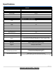
Specifications MODEL Model # 157564 FLOW OUTPUT Pressure Rating 3000 psi Flow Rate 8 gallons per minute Maximum Temperature 250 F DIMENSIONS / COMPONENTS Length 48” Width 60" Height 56" Weight 1,020 lbs. Pump Model General Pump TSF2219 Engine Model Kohler ECH730 Engine Displacement 747cc High Pressure Discharge Hose (2) 3/8" x 50' Chemical Injector Maximum dilution ratio 18:1 Battery 12 Volt, minimum 24 Amp/Hr.
Component Identification – REV.
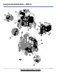
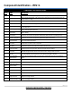
Component Identification – REV. G COMPONENT REFERENCE GUIDE REF # NAME DESCRIPTION 1 Heat Exchanger Device that heats the water by forcing a flame across steel pipe. 2 Hi-PSI Switch This is a backup safety feature. If the system pressure exceeds the set pressure limit this device will stop the burner from firing. 3 Water Outlet Connection point for the high-pressure hose. 4 Pump The device that moves fluid through a combination of suction and displacement.
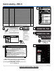
Safety Labeling – REV.
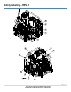
Safety Labeling – REV. H ON-PRODUCT WARNING LABELS 1 Ref. # 1 2 3 4 5 Part # 782325 786632 797513 777666 796496 Description Decal, Danger and Warning Decal, Rotating Equipment Warning Decal, Burn Hazard Decal, Gasoline Only Decal, ISO Electric Shock Warning Triangle Qty.
Special Equipment Safety Features High Pressure Safety Device (Rupture Disc) WARNING: If the high-pressure safety device ever discharges water, turn the engine off and do not use the machine. The device will no longer function properly. See a dealer or call Product Support at 1-800-969-7073. This unit is equipped with a high-pressure safety device, which acts as a safety feature. If the unloader malfunctions, the high-pressure safety device will open and relieve excess system pressure.
Assembly & Initial Set-Up Instructions – REV. H STEPS FOR ASSEMBLY / INITIAL SET-UP • Unpacking & Delivery Inspection • Connecting Battery • Attaching a Water Feed Tank (customer supplied) • Initial Pump & Engine Preparation Each of these steps will be discussed in detail below: STEP 1. UNPACKING & DELIVERY INSPECTION Find and separate the components identified in Fig. 06251 and Fig.06546 – Hardware Bag. Inspect the pressure washer immediately after you receive delivery for missing parts and damage.
Assembly & Initial Set-Up Instructions – REV. H 1 OWNER'S MANUAL 4 2 6 3 5 7 9 10 11 12 13 8 14 15 16 17 8.1 HARDWARE BAG CONTENTS REF # 1 2 3 Part # N/A 796627 796216 DESCRIPTION Manual, 157564 Nozzle, 5 Pack #9.0 Nozzle, 5 Pack #4.5 QTY. 1 1 2 4 5 6 799396 799395 N/A 9 797317 777915 777915 KO2434003 777165 221222 5370 Nozzle, #3.0 Yellow, (Steam) Nozzle, #7.0 Yellow, (Steam) Chemical Injector, 2.
Assembly & Initial Set-Up Instructions – REV. H STEP 2. ATTACHING A WATER FEED TANK (CUSTOMER SUPPLIED) It Is recommended that the water supplied to the pressure washer is by an external water tank. To connect an external water feed tank, follow the steps below: CAUTION: Inadequate plumbing between a feed tank and the pressure washer can cause damage to the pump from water cavitation. To avoid water cavitation: • Use 1" hose and fittings or larger (provided). Supply Line Hose should be no longer than 6'.
Assembly & Initial Set-Up Instructions – REV. H STEP 3. INITIAL PUMP & ENGINE PREPARATION Prepare Water Pump Verify pump oil level. Oil fill dipstick NOTICE: The pump is shipped with oil. 1. Verify that oil level is half way up the sight glass (or at the indicator line on the dip stick). 2. If oil level is low, fill with SAE Non-detergent 30wt. oil. 3. Replace oil fill dipstick. Check Engine Oil Sight glass Oil drain hose Check the engine oil before starting the pressure washer.
Assembly & Initial Set-Up Instructions – REV. H You must always ground the pressure washer as directed below when using or fueling the pressure washer on a trailer. Using a 10 AWG or larger copper grounding cable, connect one end of the grounding cable to the grounding terminal on the skid frame (see Figure 06603), and connect the other end of the grounding cable to bare metal on the trailer frame (see Figure 06603). 1. Grounding Terminal located on skid frame. 2.
Moving the Pressure Washer WARNING The pressures washer is heavy. You can be injured when trying to lift it without mechanical assistance. It can crush and cause serious injury if it drops on someone. Follow the instructions below for safely moving the pressure washer. Align the forks with the frame rails under the pressure washer skid. Lift the skid with engine facing the forklift. You will need to tip forks up to keep skid from rolling forward off the forks.
Before Each Use Follow the steps below prior to each use of the pressure washer. STEPS TO FOLLOW BEFORE EACH USE • • Check Equipment Add fuel(s) • Select a Suitable Worksite STEP 1. CHECK EQUIPMENT Check/Add Pump Oil Check/add pump oil. CAUTION: Never run the pump without enough lubrication! 1) Check oil level. Verify that oil level is half way up the sight glass (or at the indicator line on the oil fill dipstick). 2) If oil level is low, fill using SAE Non-detergent 30wt. oil.
Before Each Use • Clean Inlet Filter Perform Other Scheduled Maintenances as Needed damaged fuel tank, or a defective fuel shut-off valve Clean the water inlet filter before each use. For instructions see section Maintenance & Repair. Make sure that any other regular maintenance has been performed as prescribed in this manual in the Maintenance & Repair section. 1) Refer to the engine’s owner's manual for engine maintenance instructions. 2) Make sure battery is charged.
Before Each Use 4) Store extra fuel in a cool, dry place in a UL-approved, tightly sealed container. Fill Burner Fuel Tank (if Planning to use heated water) If you are planning to use heated water, fill burner fuel tank with #1 or #2 diesel, B5 or lower biodiesel, kerosene, or fuel oil. 1) Remove fuel cap. 2) Add fuel through the fill opening. Do not overfill. Allow at least 1/2" of empty space below fill neck to allow for fuel expansion. 3) Replace fuel cap securely before starting engine.
Before Each Use inside an enclosure. This could cause hot air deflection, heat build-up, and increased exhaust back-pressure, resulting in exhaust leakage or overheating and damage to the pressure washer. Stay Away from Combustible Dust, Liquids or Vapors Do not locate and use the pressure washer in the presence of flammable vapors, dust, gases, or other potentially combustible materials.
Operating the Pressure Washer After you have checked and fueled the equipment and positioned it in a suitable worksite, it is time to start your pressure washer. The following are the procedures necessary for safe, successful operation of your pressure washer. WARNING Carefully read and follow all instructions and safety information for using this pressure washer.
Operating the Pressure Washer 3) Release the collar, making sure it springs back and re-seats to its original (non-retracted) position (Figure 2b). Check the connection by pulling on the hose to ensure a positive connection. Coupler Figure 2b Select the Spray Nozzle High-Pressure Output Collar Your pressure washer is equipped with 15 high-pressure nozzles and 3 low-pressure nozzles. (1 #7.0 Steam and 2 #3.0 Steam nozzles).
Operating the Pressure Washer 1) Make sure the engine is off and the hose line depressurized. 2) To install the nozzle, pull the collar back and twist the nozzle firmly into the coupler on the end of the wand (Figure 3a). Nozzle Spray Gun Nozzle Figure 3a 3) Collar Coupler Lance Release the collar, making sure it springs back and re-seats to its original (non-retracted) position (Figure 3b).
Operating the Pressure Washer Follow the chemical manufacturer's label instructions for proper use and handling of the chemical. Understand all safety hazards and first aid for all chemicals being used. Always wear protective gloves when handling and cleaning with chemicals, and wear other protective gear as directed by chemical manufacturer. Always dispose of hazardous fluids per local, state, and national guidelines.
Operating the Pressure Washer leaks, fire, explosion, or other serious safety hazards, and will also void the warranty. DURING USE Stay alert. Watch what you are always doing. Clear work area. Clear the work area of all bystanders. Keep children and pets away. Dual gun use (if equipped). During dual gun use, always stay aware of the other operator’s location and keep spray directed away from them. Keep spray away from electrical wiring.
Operating the Pressure Washer Prime Water Supply Prime the water supply. CAUTION: Never run the pump without the water supply connected and primed. Operating the pressure washer without enough incoming flow of water will damage the pump. Must use a tank feed: See Assembly and Initial Set-Up. 1) Ensure the feed tank is full of water. 2) Make sure the supply hose from the tank is not kinked. A kinked hose will provide insufficient water supply to the pump and reduce its life.
Operating the Pressure Washer CAUTION: Do not run the machine in hot mode without fuel in the burner's fuel tank, or damage can occur. 3) Turn the heat switch ON and adjust the thermostat to the desired temperature. 4) If steam is desired set the thermostat to 212°F or higher and use the yellow steam nozzle. WARNING: • NEVER attempt to immediately run or re-light the burner if it does not ignite the first time. Unburned oil or gas may have accumulated, causing potential explosion or fire hazard.
Operating the Pressure Washer • unsecured, lightweight objects Procedure: 1) Put on one of the high-pressure spray nozzles (always relieve system pressure first and follow instructions for attaching a nozzle). 2) Clear the cleaning area of all persons. Keep children and pets away. 3) Hold the spray gun firmly with two hands and a sturdy stance: (gun kicks back when triggered). CAUTION: Spray gun metal gets extremely hot when using the burner and can burn you on contact.
Storing the Pressure Washer STORAGE When you are finished using the pressure washer, you must prepare the pressure washer for storage and store it in a proper location. NOTICE: If you will be storing the pressure washer in freezing conditions, follow the instructions below on how to prepare the pressure washer for freezing conditions. • If you will not be using the pressure washer again for 30 days or more, follow the instructions for preparing the engine for long-term storage.
Storing the Pressure Washer • Add fuel stabilizer to the fuel (following manufacturer's instructions) Fuel stabilizer steps: Prepare Pressure Washer for Storage Move Pressure Washer to Storage Location 1. Ensure engine fuel tank is full. 2. Add fuel stabilizer to fuel tank. 3. Run pressure washer with high pressure hose at least 5 minutes after adding stabilizer to allow it to enter the fuel system. 4. Shut off engine. Prepare the pressure washer for storage.
Maintenance & Repair BURNER ADJUSTMENT (only needed if white exhaust smoke appears) The oil burner is preset, and performance tested at the factory (elevation 1100 feet). Different altitudes may require a one-time initial burner adjustment. CAUTION: If white smoke appears from the burner exhaust vent during start-up or operation, discontinue use and readjust air bands. Specific steps for burner correction are given below.
Maintenance & Repair Inspect and maintain your pressure washer as specified below to keep it in safe and optimal working order. Follow all safety rules and recommended maintenance instructions WARNING ALWAYS shut off water supply or drain tank, relieve spray gun pressure, turn off engine and disconnect the spark plug before cleaning, adjusting, or servicing the pressure washer. After servicing, make sure all guards and cover shields are replaced before using.
Maintenance & Repair See detailed instructions for each maintenance item below. (Note: For end-of-the-season storage instructions, see the Storage section of this manual.) MAINTENANCE & REPAIR-DETAILED INSTRUCTIONS Follow Safety Rules Keep Pressure Washer Clean Read and follow these safety rules whenever you will be servicing the pressure washer: • Turn off / relieve pressure first. Always turn off pressure washer and relieve system pressure before inspection or maintenance.
Maintenance & Repair 1) 2) Clean Inlet Filter • Never use a finger or skin to check for leaks. • Never operate machine with damaged or missing hoses/parts. • Never attempt to repair a high-pressure hose or component. Always replace it with a part that is rated at or above the pressure rating of this machine. Check hoses, fittings, wand, trigger gun and connections for signs of wear, cracks, looseness, or leaks. Replace as required. Check and clean the nozzle orifice.
Maintenance & Repair Maintain Burner’s Fuel Filter/Water Separator Drain water from burner’s filter bowl before each use and replace filter after every 500 hours of use or as needed. 1) After each use of the burner, visually check the filter bowl. If any water has accumulated, drain it via the water drain at the bottom of the bowl. 2) After every 500 hours of operation, empty the burner’s fuel tank to remove the filter bowl and inspect the fuel filter/water separator. Replace filter as needed.
Maintenance & Repair Inspect Heating Coil and Desoot Inspect and desoot coil annually. Rain Cap Most coils never require desooting. However, poor grades of fuel oil or inadequate combustion air will cause heavy soot build-up on the outside surface of the heating coil tubing. These deposits will insulate the coil, which then restricts air flow through the heat exchanger and further aggravates the soot build-up. Be sure to wipe the sight glass.
Maintenance & Repair Inspect/Tighten or Replace Pump/Generator Belts Check drive belt and generator belt after the first 24 hours of use, then with each oil change. Tighten or change belts as needed. Check WARNING: Belt slippage can cause static Generator electricity build-up, which may result in tension using a sparking. Fire ignition can result. straight edge. NOTICE: Belt tension and alignment are interBelt will related. Do not adjust one without checking the have about other.
Maintenance & Repair • Inspect and Clean Flow Switch Do not apply belt dressing, which can cause damage and early belt failure. Inspect and clean flow switch as needed. Mineral build-up and/or debris within the flow switch can occur and may affect burner operation if not periodically cleaned. Mineral build-up and/or debris can stop the movement of the shuttle inside the flow switch body. Shuttle movement is important because the burner will not fire if the shuttle does not move.
Maintenance & Repair 6) Rinse body. 7) When cleaning is complete reinstall the Body into the Enclosures, taking care not to cause damage. 8) Tighten the Screws into the body until they are snug. Do not overtighten the screws. 9) Body (Female Guides) Shuttle (Male Tabs) Rounded End First Insert the Shuttle Assembly with the rounded end first, into the body. Align with grooves. 10) Inspect the O-ring on the Cap, if it is damaged, replace the entire flow switch assembly.
Maintenance & Repair ENGINE WILL NOT START Solutions Fill engine with the adequate amount of oil. Choke engine to start. Add fuel. Recharge/Replace battery. Attach spark plug wire to spark plug (If equipped). Causes Low oil shutdown Cold engine No fuel Dead battery Spark plug wire not attached (If equipped) PRESSURE WASHER RUNS BUT BURNER DOESN’T FIRE Solutions Turn heat switch ON. Set thermostat to desired temp. Fill fuel tank with kerosene, diesel, or fuel oil. Call Product Support.
Major Components – REV. H MAJOR COMPONENTS (FIG.06586) Ref. # 1 2 3 4 Description Heat Exchanger Blower Housing Pump, Engine & Generator Skid (Roll Cage) Skid Frame These components go into more detail on the following pages.
Parts Explosion (Heat Exchanger/Blower) – REV.
Parts Explosion (Heat Exchanger/Blower) – REV. H HEAT EXCHANGER (FIG.06442) Ref. # 1 Part # 798394 1.1 1.2 1.3 1.4 1.5 1.6 1.7 1.8 1.9 1.10 1.11 1.12 1.13 1.14 1.15 1.16 1.17 1.18 1.19 1.20 1.21 1.22 1.23 1.24 1.25 1.26 1.27 1.28 1.29 1.30 1.31 1.32 1.33 1.34 1.35 1.36 1.37 1.38 1.39 1.
Parts Explosion (Heat Exchanger/Blower) – REV. H HEAT EXCHANGER (FIG.06442) Continued Ref. # 4 Part # NA 4.1 4.2 4.3 797317 777915 777915 Description Chemical Injector, Assembly Chemical Injector, 3/8” Nipple, QC 3/8” Nipple, QC 3/8” x 3/8” FNPT Qty.
Parts Explosion (Heat Exchanger/Blower) – REV. H BLOWER HOUSING (FIG.06443) Ref. # Part # Description 1 2 3 4 5 6 7 797652 82155 797647 82624 797555 82090 797554 HX 8GPM blower housing Tie, cable black, 50# 11 HX intake boot, 8 GPM Bolt, 3/8-16 X1" hex head HX 8GPM blower impeller Bolt, Carriage. Gr5Z, 5/16 X .75 HX 8 GPM blower, motor mount 1 2 1 2 1 2 1 1 1 1 1 1 1 2 2 1 3 2 1 2 8 798404 Qty.
Parts Explosion (Pump, Engine, & Generator) – REV. H PUMP, ENGINE, GENERATOR (FIG.06270) Ref.
Parts Explosion (Pump, Engine, & Generator) – REV. H PUMP, ENGINE, AND GENERATOR BASE WITH ISO MOUNTS (FIG.06154) Ref. # 1 2 3 Part # 792840 795030 82628 Description Base for the Pump, Engine, and Generator Head Rubber Grommet Bolt, 1/2"-13 x 2-1/2" hex head Qty. 1 3 4 4 5 6 7 8 9 10 793909 795645 82632 82627 82686 794460 82631 Iso Mount for Pump, Engine and Generator Base Iso Mnt Red/Gold 155 Lbs Tech Prod.
Parts Explosion (Pump, Engine, & Generator) – REV. H ENGINE/BELTS/PULLEYS (FIG.06271) Ref. # 1 2 3 4 Part # 798463 KO2408303s KO5205002s KO2505042s 796339 82631 82626 Description Engine-26.5HP Kohler ECH749 Filter, Air Filter, Oil Filter, Engine Fuel Oil Drain Kit 3/8" NPT P Nut, 3/8"-16 hex flange nylon 3/8"-16 x 2.50" Hex Head Flange Bolt GRD 5 5 6 7 794405 794393 779529 1 1 1 3 5 1 1 1 1 1 1.1 1.2 1.3 8 9 10 82627 82037 793855 Sheave, 3A9.0B9.
Parts Explosion (Pump, Engine, & Generator) – REV. H ENGINE/BELTS/PULLEYS (FIG.06271) Continued Ref. # 14 15 16 17 17.1 18 Part # 82474 794401 784049 794407 19 20 21 22 793926 794406 82142 33562 798591 82621 Description Bolt, 1/2"-13 X 3.5 hex head serrated flange Sheave 4A3.6B4.0-SD Key, 3/8" X 3/8" X 2.5" Bushing, SD 1-7/16" Bolt with lock washer for Kohler Engine Bushing Bolt, 5/16"-18 x 3/4" hex head flange Qty.
Parts Explosion (Pump, Engine, & Generator) – REV. H PUMP (FIG.06155) Continued Ref. # 3 4 5 6 7 Part # 82624 82706 82201 82631 796339 Description Bolt, 3/8”-16 x 1” hex head flange, Gr. 5 Bolt, M10x1.5-25MM SHCS Washer, M10 Flat Nut, 3/8"-16 hex flange nylon Oil Drain Kit 3/8" NPT P Qty.
Parts Explosion (Pump, Engine, & Generator) – REV. H GENERATOR HEAD (FIG. 06157) Ref.
Parts Explosion (Skid) (Roll Cage) – REV. H Skid (Roll Cage) (FIG.06266) Ref.
Parts Explosion (Skid) (Roll Cage) – REV. H FUEL TANK HOUSING (FIG.06267) Ref. # 1 2 3 Part # 787827 796861 796606 4 Description Decal, Diesel, Kerosene or Fuel Oil Only Decal, Burner Fuel tank Burner Tank Front Cover 793217 4.1 793225 Qty.
Parts Explosion (Skid) (Roll Cage) – REV. H FUEL TANK HOUSING (FIG.06267) Continued Ref. # 18 19 20 21 - Part # 795993 796862 777666 82649 82301 Description Engine Tank Front Cover Decal, Engine Fuel Tank Decal, Gasoline Only Blind rivet, 3/16" Washer, 5/16" external star (not shown) Qty. 1 1 1 26 3 Ref. # Part # Description 1 2 82222 798575 Nut, 1/4-20 nylon insert lock Fuel Pump, 2-3.
Parts Explosion (Skid) (Roll Cage) – REV. H FUEL ROUTING MANAGEMENT SYSTEM (FIG.06346) Continued Ref. # 14 15 16 17 18 Part # 796282 783212 82621 793206 82630 Description Fitting, 1/4" HB x 1/4" FPT Elbow, 1/4" MPT x 1/4" HB Bolt, 5/16"-18 x 3/4" hex head flange Fuel hose bracket Nut, 5/16"-18 nylon insert lock Qty. 1 1 10 1 10 BURNER FUEL LINE ROUTING (FIG.06268) Ref. # Part # Description 1 2 3 4 798361 798362 798215 793645 Hose, 1/4" Fuel Line –Fuel tank to fuel filter/water separator (4.
Parts Explosion (Skid) (Roll Cage) – REV. H ENGINE FUEL LINE ROUTING (FIG.06269) Continued Ref. # 4 5 6 7 Part # 777834 798366 798363 785767 Description Clamp, 1/4" Hose Hose, 1/4" Fuel Line – Return Line from Engine to Carbon Canister (7.5’ long) Hose, 1/4" Fuel Line – Supply Line - from Fuel Pump to Engine (5.3’ long) Hose mender, 1/4" x 3/16" nylon Qty. 8 1 1 1 BATTERY HOUSING (FIG.06082) Ref. # Part # Description Qty.
Parts Explosion (Skid) (Roll Cage) – REV. H SPRAY GUN MOUNT (FIG.06084) Ref. # Part # Description Qty. 1 796940 Upper gun mount (Lance Rest) 1 2 797021 Detent pin with lanyard 2 3 82630 Nut, 5/16"-18 nylon insert lock 6 4 82059 10-24 x 1/2" Phillips Head Screw 2 5 796612 Lower gun mount 1 6 82065 Nut, #10-24 nylon insert lock 2 7 82621 Bolt, 5/16-18 x 3/4" hex head flange 6 SPRAY GUNS (FIG.06077) Ref. # Part # Description Qty. 1 791279 Lance, 28" Viton Coupler 2 1.
Parts Explosion (Skid) (Roll Cage) – REV. H UNLOADER (FIG.06083) Ref. # 1 2 Part # 798351 798264 Description Hose, 3/4” x 8’ Hose, 3/8” X 31” 3 4 5 6 7 8 796618 796160 777838 777337 777409 796502 Clamp, T-bolt 1.06” - 1.
Parts Explosion (Skid) (Roll Cage) – REV. H UNLOADER PARTS LIST (PART #796502) Ref. # Part # Description 1 2 3 4 5 6 GPY10306601 GPY60180951 GPY60180851 GPY60182231 GPY10401075 GPY10317175 O-Ring, 1.78x15.6 Seat, 11.6x19x6, SST Shutter Pin, M8, SST Spacer Ring, Brass Stem Seal O-Ring Qty. 1 1 1 1 1 1 7 8 9 10 11 12 GPY60182331 GPY60172831 GPY16210000 GPY10307201 GPY10306801 GPY60185135 Piston Holder, Brass Ring Nut, M27x1, Brass Screw, M4x4, set O-Ring, 1.78x20.35 O-Ring, 1.75x17.
Parts Explosion (Skid) (Roll Cage) – REV. H CONTROL BOX (FIG.06347) Ref.
Parts Explosion (Skid) (Roll Cage) – REV. H CONTROL BOX (FIG.06347) Continued Ref. # 15 16 17 18 19 Part # 798913 782120 798912 782122 798911 Description #9.0 - 25Deg (Green) 1/4" Quick Connect Stainless Steel Nozzle #4.5 - 15Deg (Yellow) 1/4" Quick Connect Stainless Steel Nozzle #9.0 - 15Deg (Yellow) 1/4" Quick Connect Stainless Steel Nozzle #4.5 - 0Deg (Red) 1/4" Quick Connect Stainless Steel Nozzle #9.
Parts Explosion (Skid) (Roll Cage) – REV. H CONTROL BOX ASSEMBLY (FIG.06433) Continued Ref. # 7 8 9 10 11 Part # 791661 797044 797050 797051 797052 Description Thermostat board Led indicator light Hour meter Heat switch Thermostat knob Qty.
Parts Explosion (Skid) (Roll Cage) – REV. H SKID FRAME (FIG.06078) Continued Ref. # 5 6 7 8 9 Part # 82621 82624 15431 795301 82631 10 11 12 13 14 15 82096 798641 798209 796619 779496 793010 Description Bolt, 5/16"-18 x 3/4” hex head flange Bolt, 3/8-16 x 1” hex head flange, Gr. 5 Bumper, Large Shock (2-1/2) Inlet Filter Nut, 3/8-16 hex flange nylon Qty. 2 22 4 1 22 Bolt, 5/16-18 x 3-1/2” Hose, 1” x .833’ PVC Suction Hose, 1” X 4’ PVC Suction Clamp, 1.34”-1.
Parts Explosion (Generator Head) – REV. H GENERATOR HEAD (PART #795080) Ref. # 1 2 3 4 Part # N/A N/A N/A N/A Description Front Cover Brand Cover Stator Assembly Rotor Assembly Qty. 1 1 1 1 5 6 7 8 9 10 N/A N/A N/A 796000 798210 798211 Washer Rear Cover Bolt, M6 x 8” HF Carbon Brush Terminal Block End Cover 2 1 4 1 1 1 11 12 13 14 82681 798212 N/A 795997 Bolt, M5-.
Parts Explosion (Pump) – REV. H GP TSF2219 PUMP (PART #794390) Ref # 1 2 3 4 5 6 7 8 9 10 11 12 13 14 15 16 17 18 19 20 21 22 23 24 25 26 Part # GP66120141 GP99380100 GP90385700 GP36203366 GP36203476 GP94738800 GP36203551 GP90516500 GP66130041 GP36712701 GP99303900 GP47151222 GP701147 GP90387700 GP70211801 GP90075600 GP91838000 GP66010022 GP98210600 GP66020035 GP91489200 GP66030001 GP90392200 GP66160022 GP99188400 GP90405100 Description Manifold, Ø22mm Head bolt M10 x 90 O-ring, Ø23.81 x 2.
Parts Explosion (Pump) – REV. H GP TSF2219 PUMP (PART #794390) Continued Ref.
Schematic Drawing Any Questions, Comments, Problems, or Parts Orders Call NorthStar ProSHOT Product Support 1-800-969-7073 67 | P a g e
Schematic Drawing OUTER BOX 3 1B 1B 17 11 16 17 1D 1C 1C 6B 7 6B N1K 8 L 7 GND NOTES:THIS LINEREPRESENTS WHITE CABLE.
Schematic Drawing 1B 1B 1D 17 7 6B L GND 3 11 16 1C 1C N1K 8 16A-DOWN GFCI GND GND 15A 17B-DOWN 18 19 17A-UP N1J 8 7 6B 5A Any Questions, Comments, Problems, or Parts Orders Call NorthStar ProSHOT Product Support 1-800-969-7073 69 | P a g e
FUEL PUMP GREY CONNECTOR BL 10A FUSE KOHLER ENGINE W W W G Y E C 10A FUSE R W A D B 5 TERMINAL CONNECTOR BL OIL PRESSURE SWITCH STARTER MOTOR DB 5WIRE CONNECTION TO KEY SWITCH +R 12VDC BATTERY -BL Schematic Drawing Any Questions, Comments, Problems, or Parts Orders Call NorthStar ProSHOT Product Support 1-800-969-7073 70 | P a g e
Summary of Important Safety Information This section provides a summary of the various safety procedures and measures that have been presented throughout the manual. Keep this summary handy and refer to it to refresh your memory about how to safely use your pressure washer. DANGER Carefully read and follow all instructions and safety information for using this pressure washer.
Summary of Important Safety Information ventilation. If you start to feel sick, dizzy, or weak while using the pressure washer, shut off the engine and get to fresh air RIGHT AWAY. • NEVER run pressure washer in an enclosed or partially enclosed location such as a building, garage, shed, or vehicle. Running a fan or opening windows will not provide adequate ventilation to prevent dangerous CO build-up. • Adequate ventilation.
Summary of Important Safety Information • • glasses with side and top protection, face protection, and protective clothing when operating the machine. If spraying pressure washer specific cleaning chemicals, wear a respirator or mask to avoid inhalation of vapors if directed on the chemical label. Wear non-slip footwear. Use of pressure washer can create puddles and slippery surfaces. Wear footwear capable of maintaining a good grip on wet surfaces. Check sprayer nozzle.
Summary of Important Safety Information • Hot exhaust/parts. Stay clear of engine and burner exhausts. Never touch hot engine muffler, burner/heating coil, or other hot surfaces. All are extremely hot and will burn you. • Hot spray gun metal when using burner. Never touch the metal screw or any metal parts of the spray gun when the heater is being used – the metal gets extremely hot and will burn you. • Smoking/sparks.
Limited Warranty Dear Valued Customer: The NorthStar ProSHOT Product you just purchased is built with the finest material and craftsmanship. Use this product properly and enjoy the benefits from its high performance. By purchasing a NorthStar ProSHOT product, you show a desire for quality and durability. Like all mechanical equipment this unit requires a due amount of care. Treat this unit like the high-quality piece of machinery it is. Neglect and improper handling may impair its performance.
Limited Warranty “Consumer use” means personal residential household use by a consumer. “Commercial use” means all other uses, including use for commercial, income producing or rental purposes or when purchased by a business. This warranty applies to the original purchaser of the equipment (verification of purchase, in the form of a receipt, is the responsibility of the buyer), is non-transferable, and covers parts and labor.
This page is intentionally left blank 77 | P a g e Any Questions, Comments, Problems, or Parts Orders Call NorthStar ProSHOT Product Support 1-800-969-7073
WARNING: This product can expose you to chemicals including gasoline engine exhaust, which is known to the State of California to cause cancer, and carbon monoxide, which is known to the State of California to cause birth defects or other reproductive harm. For more information go to www.P65Warnings.ca.gov. Manufactured by Northern Tool + Equipment Co., Inc. Burnsville, MN 55306 NorthernTool.