
Manual
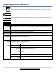
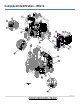
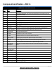
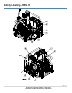
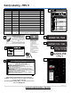

Table Of Contents

Component Identification – REV. G
7 | P a g e
Any Questions, Comments, Problems, or Parts Orders
Call NorthStar ProSHOT Product Support 1-800-969-7073
COMPONENT REFERENCE GUIDE
REF #
NAME
DESCRIPTION
1
Heat Exchanger
Device that heats the water by forcing a flame across steel pipe.
2
Hi-PSI Switch
This is a backup safety feature. If the system pressure exceeds the set pressure limit this device will
stop the burner from firing.
3
Water Outlet
Connection point for the high-pressure hose.
4
Pump
The device that moves fluid through a combination of suction and displacement.
5
Indicator Light (Heat)
Instrument used to monitor unit operation. Will illuminate when the burner has power when heat switch
is in the ON position.
6
Indicator Light (Spraying)
Instrument used to monitor unit operation. Will illuminate when the gun trigger is being squeezed and
water is flowing though the spray gun.
7
Indicator Light
(Thermostat)
Instrument used to monitor unit operation. Will illuminate when the gun trigger is being squeezed and
water is heating.
8
Indicator Light
(Burner Motor)
Instrument used to monitor unit operation. Will illuminate when the blower is operating properly.
9
Indicator Light (Ignition)
Instrument used to monitor unit operation. Will illuminate when burner is firing.
10
Thermostat Knob
Turn to adjust water temperature.
11
Heat Switch
On/Off device for power to burner components.
12
Hour Meter
Indicates the number of hour’s the pressure washer has been used.
13
Engine Key Switch
Start the engine by turning clockwise. (Refer to the engine manual for details.)
14
Control Box
Mounted housing that holds electrical controls for the burner. Storage location for nozzles.
15
Unloader
Valve that regulates pressure and directs flow into bypass when trigger is released.
16
Burner Fuel Filter/
Water Separator
Used to remove contaminant water from burner fuel to prevent water in the fuel from reaching the
burner.
17
Gun Mount
Location to secure up to 3 spray guns.
18
Manual Tube
Storage location for Owner’s Manual.
19
Engine (see engine’s
owner’s manual)
The air-cooled engine powers the pump and generator.
20
Generator
Powers burner components with 120V AC electricity.
21
Battery Box
Storage compartment to house the battery.
22
Water Inlet
Used to connect water from the feed tank to the inlet plumping.
23
Engine Fuel Tank
Engine fuel storage container.
24
Diesel/Kerosene/Fuel Oil
Burner fuel storage container.