30-Gallon Electric Air Compressor Owner’s Manual WARNING: Read carefully and understand all ASSEMBLY AND OPERATION INSTRUCTIONS before operating. Failure to follow the safety rules and other basic safety precautions may result in serious personal injury.
Thank you very much for choosing a NorthStar® product! For future reference, please complete the owner’s record below: Serial Number/Lot Date Code: ________________________________ Purchase Date: ____________________________________________ Save the receipt, warranty, and this manual. It is important that you read the entire manual to become familiar with this product before you begin using it. This air compressor is designed for certain applications only.
Table of Contents Intended Use .......................................................................................................................................... 5 Packaging Contents .............................................................................................................................. 5 Technical Specifications ...................................................................................................................... 5 Safety Signal Words ..........................
Pump Oil...............................................................................................................................................22 Compressor Pump Oil .................................................................................................................... 22 Checking Oil ................................................................................................................................... 22 Changing Oil .........................................................
Intended Use The NorthStar 30-Gallon Electric Air Compressor provides compressed air for air tools and pressurized objects that require high air pressure. It features: • Maximum Efficiency: Heavy-duty induction motor for maximum performance and efficiency. • Long Lasting Operation: Cast iron oil-lubricated pump for long service life. • Versatile Operation: Dual voltage motor is wired for standard 120V outlets but can be converted to 240V applications.
Important Safety Information ⚠WARNING • Read and understand all instructions. Failure to follow all instructions may result in serious injury or property damage. • The warnings, cautions, and instructions in this manual cannot cover all possible conditions or situations that could occur. Exercise common sense and caution when using this tool. Always be aware of the environment and ensure that the tool is used in a safe and responsible manner.
to handle the product. • Be aware of all power lines, electrical circuits, water pipes, and other mechanical hazards in your work area. Some of these hazards may be hidden from your view and may cause personal injury and/or property damage if contacted. • Keep your work area clean and well lit. Ensure floors are not slippery from wax or dust. • The compressed air directly from your compressor is not safe for breathing.
application. • Do not overreach. Keep proper footing and balance at all times. • Remove keys or wrenches before connecting the tool to an air supply, power supply, or turning on the tool. A wrench or key that is left attached to a rotating part of the tool may cause personal injury. • Secure the work with clamps or a vise instead of your hand when practical. This safety precaution allows for proper tool operation using both hands.
• To provide proper ventilation for cooling, the compressor must be kept a minimum of 12 inches (31 cm) from the nearest wall, in a well–ventilated area. • Fasten the compressor down securely if transporting is necessary. Pressure must be released from the tank before transporting. • Protect the air hose and electric cord from damage and puncture. Inspect them weekly for weak or worn spots and replace if necessary. • To reduce the risk of electric shock, do not expose to rain. Store indoors.
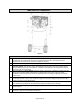
Main Parts of Compressor Figure A Components 1. Safety Valve: This valve is designed to prevent system failures by relieving pressure from the system when the compressed air reaches a predetermined level. The valve is preset by the manufacturer and must not be removed or modified in any way. 2. Tank Pressure Gauge: The tank pressure gauge indicates the reserve air pressure in the tank. 3. 4. 5. 6. 7. 8.
Components 9. 10. Motor Overload Protector: The motor has a thermal overload protector. If the motor overheats for any reason, the overload protector will shut off the motor. The motor must be allowed to cool down before restarting. To restart: 1. Set the Auto/Off switch to OFF (O) and unplug unit. 2. Allow the motor to cool. 3. Depress the red reset button on the motor. 4. Plug the power cord into the correct branch circuit receptacle.
Assembly ⚠WARNING • This compressor was shipped with oil in the pump crankcase. Check oil before operating the air compressor. Unpack the air compressor. Inspect the unit for damage. If the unit has been damaged in transit, contact the carrier and complete a damage claim. Do this immediately because there are time limitations to damage claims.
Disconnecting Hoses 1. Ensure regulated pressure gauge reads 0 PSI. 2. Remove hose from air outlet. Installation Lubrication and Oil The air compressor pump was filled WITH oil at the manufacturer. Check air compressor pump oil level before operating unit. See the Compressor Pump Oil section under Pump Oil. Compatibility Air tools and accessories that are run off the compressor must be compatible with petroleum-based products.
Wiring Instructions A qualified electrician needs to know the following before wiring: 1. The amperage rating of the electrical box should be adequate. Refer to the Technical Specifications (page 4) for this information. 2. The supply line should have the same electrical characteristics (voltage, cycle, phase) as the motor. Refer to the motor nameplate, on the side of motor, for this information. NOTE: The wiring used must be rated for the motor nameplate voltage.
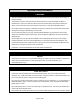
Extension Cords ⚠WARNING • USE A PROPER EXTENSION CORD. Make sure your extension cord is in good condition. When using an extension cord, be sure to use one heavy enough to carry the current your product will draw. An undersized cord will cause a drop in line voltage, resulting in loss of power and cause overheating. • Be sure your extension cord is properly wired and in good condition. Always replace a damaged extension cord or have it repaired by a qualified person before using it.
Nameplate AMPS 0-6 6-10 10-12 12-16 Minimum Wire Size of Extension Cords Cord Length 25' 50' 100' 150' 18 AWG 16 AWG 16 AWG 14 AWG 18 AWG 16 AWG 14 AWG 12 AWG 16 AWG 16 AWG 14 AWG 12 AWG 12 AWG 12 AWG NOT RECOMMENDED • If you are using an extension cord outdoors, make sure it is marked with the suffix W-A (W in Canada) to indicate it is acceptable for outdoor use. • Make sure your extension cord is properly wired and in good electrical condition.
NOTE: Some models are equipped with a dual voltage motor 115/230-volt. Most models are factory wired for 115-volt operation. If conversion from 115-volt to 230-volt is required, refer to the motor nameplate and have the conversion completed by a licensed electrician. Reset Switch Figure E How to Use Your Unit ⚠WARNING • Do not operate this unit until you read this instruction manual for safety, operation, and maintenance instructions. Figure F How to Stop Set the Auto/Off switch to OFF.
This procedure is required before the air compressor is put into service and when the check valve or a complete compressor pump has been replaced. 1. Make sure the Auto/Off switch is in the OFF position. 2. Check the oil level in the pump. See the Checking Oil section in Pump Oil for instructions. 3. Plug the power cord into the correct branch circuit receptacle. (Refer to Voltage and Circuit Protection paragraph in the Grounding section of this manual.) 4.
⚠CAUTION • Risk of unsafe operation. Compressed air from the unit may contain water condensation and oil mist. Do not spray unfiltered air at an item that could be damaged by moisture. Some air tools and accessories may require filtered air. Read the instructions for the air tools and accessories. Operating Instructions ⚠WARNING • Risk of bursting. If any unusual noise or vibration is noticed, stop the compressor immediately and have it checked by a trained service technician. How to Start 1.
Maintenance ⚠WARNING • Risk of unsafe operation. Unit cycles automatically when power is on. When performing maintenance, you may be exposed to voltage sources, compressed air, or moving parts. Personal injuries can occur. Before performing any maintenance or repair, disconnect power source from the compressor and bleed off all air pressure. • Risk of bursting. If the safety valve does not work properly, over-pressurization may occur, causing air tank rupture or an explosion. • Risk of burn.
Maintenance Interval Maintenance Point * To check for air leaks, apply a solution of soapy water around joints. While compressor is pumping to pressure and after pressure cuts out, look for air bubbles to form. ** The pump oil must be changed after the first 20 hours of operation. Thereafter, when using synthetic blend, non-detergent air compressor oil, change oil every 100 hours of operation or once a year, whichever comes first. + Perform more frequently in dusty or humid conditions.
NOTICE: Risk of property damage. Drain the water from the air tank may contain oil and rust which can cause stains. 6. After the water is drained, close the drain valve (clockwise). The air compressor can now be stored. NOTE: If the drain valve is plugged, release all air pressure. The valve can then be removed, cleaned, and reinstalled. Pump Oil Compressor Pump Oil NOTICE: Risk of property damage. Use air compressor oil only.
Figure I Belt Replacement / Belt Tension / Motor Pulley & Flywheel Adjustment ⚠WARNING • This unit starts automatically. ALWAYS shut off and unplug the compressor and bleed all pressure from the system before servicing the compressor, and when the compressor is not in use. Do not use the unit with the shrouds or belt guard removed. Serious injury could occur from contact with moving parts. • Hot surfaces. Risk of burn. Pump head and surrounding parts are very hot; do not touch.
Adjusting Belt Tension 1. Slide the motor into its original position and line the motor up with the mark made earlier on the saddle. 2. Tighten the two outside motor mounting screws enough to hold the motor in place for checking pulley and flywheel alignment. 3. The belt should deflect 1/2” (13mm) at midway between the pulley and the flywheel when a 5-pound (2.26 kg.) weight is applied at the midway point. 4. When proper belt tension is achieved, tighten all four motor mounting screws. Torque to 20-25 ft.
Inspect Air Lines and Fittings for Leaks 1. Set the Auto/Off lever to OFF, unplug the unit, and relieve all air pressure from the air tank. 2. Apply a soap solution to all air line fittings and connections/piping. 3. Correct any leaks found. IMPORTANT: Even minor leaks can cause the air compressor to overwork, resulting in a premature breakdown or inadequate performance. Air Compressor Head Bolts - Torqueing The air compressor pump head bolts should be kept properly torqued.
Troubleshooting Failure Air leaks Possible Cause Fittings are not tight Corrective Action Tighten fittings where air can be heard escaping. Check fittings with soapy water solution. DO NOT OVERTIGHTEN. Air tank must be replaced. Do not repair the leak. Air leaks in air tank or at air tank welds Defective air tank Warning: Risk of bursting. Do not drill into, weld, or otherwise modify air tank or it will weaken. The air tank can rupture or explode.
Failure Possible Cause Oil level is too high Reduce oil to proper level. See Compressor Pump Oil under Pump Oil. Defective safety valve Operate safety valve manually by pulling on the ring. If the valve still leaks, it must be replaced. Loose belt Check belt tension. See Adjusting Belt Tension under Belt Replacement / Belt Tension / Motor Pulley & Flywheel Adjustment. Loose pulley Tighten pulley set screw, torque to 15-20 ft./lb. (20.3-27.1 Nm).
Failure Possible Cause Fittings are not tight Moisture in pump crankcase Moisture in pump crankcase Compressor won’t start in cold temperatures Corrective Action Tighten fittings where air can be heard escaping. Check fittings with soapy water solution. DO NOT OVERTIGHTEN. Leaking seals Unit operating in damp or humid conditions Contact an authorized service center. Detergent type oil being used in pump Drain oil and refill pump with synthetic blend, non-detergent air compressor oil.
Failure Pressure reading on the regulated pressure gauge drops when an accessory is used. Regulator knob has continuous air leak Regulator will not shut off air outlet Air tank pressure will not build Compressor stalls Overheating Possible Cause Corrective Action Regulator is not adjusted correctly for accessory being used. It is normal for some pressure drop to occur when an accessory is used.
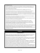
Air Compressor Parts Diagram Air Compressor Parts List Reference 1 2 3 4 5 6 7 9 10 11 12 Part Number 125-0175 061-0255 007-0010 146-0016 061-0238 006-0018 059-0012 125-0174 061-0212 060-0146 068-0092 Part Description Belt guard, outer wire Screw, 5M x 20mm V-belt, 4L-460 Key Setscrew, 5/16”-18 Pulley Bolt, 5/16 x 1/2 Belt guard, inner, wire Screw, #10-32 x 3/4” Washer, #10 Connector Page 30 of 36 Quantity 1 5 1 1 2 1 4 1 1 1 1
Reference 13 14 15 16 17 18 19 20 21 22 23 24 25 26 27 28 29 30 31 32 33 34 35 36 37 38 39 40 41 42 43 44 45 46 47 48 49 50 Part Number 058-0007 145-0478 031-0037 145-0324 064-0056 058-0174 114-0619 160-0345 026-0233 153-0153 095-0081 033-0001 094-0029 512-0035 072-0006 512-0039 513-0002 098-3870 065-0005 026-0030 034-0184 032-0025 136-0077 136-0090 065-0004 019-0167 032-0056 036-0031 071-0033 061-0216 093-0031 059-0010 098-2856 059-0410 060-0023 060-0217 103-0205 Part Description Nut, 3/8” O.D.
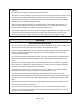
Pump Parts Diagram Pump Parts List Reference 1 2 3 4 5 6 7 8 9 9A 10 11 12 13 14 15 16 17 Part Number 145-0486 065-0107 061-0238 060-0224 042-0121 046-0302 043-0207 046-0303 019-0305 019-0328 054-0250 069-0028 048-0121 047-0099 050-0065 058-0188 060-0222 059-0420 Part Description Tube with compression nuts Elbow Socket head cap screw, M6 x 40mm Washer, M6 Head, cylinder Gasket, cylinder head Valve plate assembly (includes items 6 and 8) Gasket, cylinder Filter assembly (includes item 9A) Filter element R
Reference 17a 18 19 20 21 22 23 24 25 26 27 28 29 30 31 32 33 34 34a 35 36 37 38 39 40 Part Number 059-0460 046-0304 060-0195 056-0078 032-0126 062-0066 049-0061 051-0103 053-0107 051-0104 046-0306 046-0364 045-0059 059-0415 044-0082 060-0225 059-0416 056-0079 060-0236 146-0026 165-0277 046-0307 S040-0469 068-0092 114-0619 Part Description Stud bolt, M8 x 35 Gasket, crankcase Washer, breather Oil fill plug Oil sight glass with O-ring Oil drain plug Crankcase Bearing, ball 204 Crankshaft Bearing, ball 205
Limited Warranty Dear Valued Customer: The NorthStar® Product you just purchased is built with the finest material and craftsmanship. Use this product properly and enjoy the benefits from its high performance. By purchasing a NorthStar® product, you show a desire for quality and durability. Like all mechanical equipment, this unit requires a due amount of care. Treat this unit like the high-quality piece of machinery it is. Neglect and improper handling may impair its performance.
chemicals, use of replacement parts which do not conform to manufacturer’s specifications, and damage related to rodent and/or insect infestation and damage caused by vandalism. EXCEPT AS PROVIDED HEREIN, NORTHSTAR® BY AND THROUGH ITS OWNER NORTHERN TOOL & EQUIPMENT COMPANY, INC. (“NTE”) HEREBY DISCLAIMS ALL WARRANTIES (WHETHER EXPESS, STATUTORY, OR IMPLIED) INCLUDING WITHOUT LIMITATION THE IMPLIED WARRANTIES OF MERCHANTABILITY, FITNESS FOR A PARTICULAR PURPOSE, AND NON-INFRINGEMENT.
Distributed by: Northern Tool & Equipment Company, Inc. Burnsville, Minnesota 55306 www.northerntool.com Made in U.S.A.