
Product Manual

Page 10 of 36
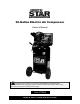
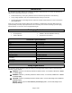
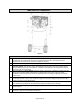
Main Parts of Compressor
Figure A
Components
1.
Safety Valve: This valve is designed to prevent system failures by relieving pressure from the
system when the compressed air reaches a predetermined level. The valve is preset by the
manufacturer and must not be removed or modified in any way.
2.
Tank Pressure Gauge: The tank pressure gauge indicates the reserve air pressure in the tank.
3.
Pressure Switch: The pressure switch automatically starts the motor when the air tank pressure
drops below the factory set cut-in pressure. It stops the motor when the air tank pressure reaches
the factory set cut-out pressure.
4.
Pressure Auto (-) / Off (O) Switch: Place this switch in the AUTO (-) position to provide automatic
power to the pressure switch and OFF (O) to remove power at the end of each use. NOTE:
ALWAYS ensure the switch is in the OFF (O) position before removing or replacing the pressure
switch cover.
5.
Air Intake Filters: The filters are designed to clean air entering the pump. To ensure the pump
continually receives a clean, cool, and dry air supply, the filters must always be clean and the filter
intakes must be free from obstructions.
6.
Air Compressor Pump: The pump compresses air into the air tank. Working air is not available until
the compressor has raised the air tank pressure above that required at the air outlet.
7.
Belt Guard: This covers the engine pulley, pump flywheel, and belt. Never operate without the belt
guard in place.
8.
Motor: The electric motor powers the pump. The electric motor is equipped with an overload
protector to help prevent possible motor burnout.