M990990D.1 ITEM NUMBER: 990990, 990991 SERIAL NUMBER: _____________ Owner’s Manual Pressure Washer: Machine that cleans dirty surfaces with high pressure water. Instructions for Installation/Set-up, Operation, Maintenance, & Storage This pressure washer produces cold-water high-pressure spray. Cleaning chemicals may be incorporated into the spray if desired. The pressure pump for this equipment is powered by an electric motor.
Table of Contents Equipment Protection Quick Facts ........................................................................................................................................ 1 TABLE OF CONTENTS ................................................................................................................................................ 2 ABOUT YOUR PRESSURE WASHER .........................................................................................................................
TROUBLESHOOTING ................................................................................................................................................ 25 PARTS EXPLOSION- MODEL #990990, 990991 REV-D.1 ....................................................................................... 26 PARTS LIST - MODEL #990990, 990991 ................................................................................................................... 27 PUMP ASSEMBLIES – 4DX, 4DNX ............................
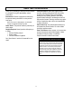
About Your Pressure Washer Thank you for purchasing a NorthStar Pressure Washer! It is designed for long life, dependability, and top performance. Personal Protection. Wear safety apparel during operation, including safety glasses with side and top protection. Ear protection is also recommended if working near any operating machine. Other safety apparel includes waterproof, insulated gloves and nonslip protective footwear.
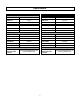
Specifications 990990 990991 FLOW OUTPUT FLOW OUTPUT PSI (bar) 2000 (138) PSI (bar) 1.5 (5.7) 140° F (60°C) GPM (I/min) Max Water Temp 3000 (207) Max Water Temp MOTOR Motor Horsepower Ampere Voltage 2.5 (9.4) 140°F (60°C) GPM (I/min) MOTOR 2.0 HP 20A 120V Motor Horsepower Ampere Voltage DIMENSIONS/COMPONENTS 5.0 HP 30A 230V DIMENSIONS/COMPONENTS Length 34.00″ Length 34.00″ Width 21.00″ Width 21.00″ Height 38.00″ Height 38.
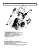
Component Identification 14 1 7 8 10 11 15 9 2 4 16 13 12 6 Fig990990-1 5 1. 2. 3. 4. 5. 6. 7. 8. 9. 10. 11. 12. 13. 14. 15. 16. Handle: Designed for easy cart movement. Hose Hook: Store hose on hook. Pressure Hose: Attach quick couplers to gun and water outlet. Chemical Hose: Submerge in cleaning solution. Water Pump: Inspect for loose/broken parts prior to each use. Motor: Leeson motor provides years of reliable use. Gun Hook: Store gun on hook.
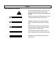
Safety Hazard Signal Word Definitions This is the safety alert symbol. It is used to alert you to potential personal injury hazards. Obey all safety messages that follow this symbol to avoid possible injury or death. DANGER (red) indicates a hazardous situation, which if not avoided, will result in death or serious injury. DANGER WARNING (orange) indicates a hazardous situation, which if not avoided, could result in death or serious injury.
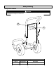
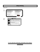
Safety Labeling Safety Decal Locations WARNING ALWAYS make sure safety labels are in place and in good condition. If a safety label is missing or not legible, order new labels from NorthStar Product Support at 1-800-270-0810.
Safety Labeling Safety Decals START-UP INSTRUCTIONS 1. Attach garden hose. 2. Attach pressure hose. 3. Attach gun and lance. 4. Turn water supply ON. 5. Squeeze trigger to purge air from pump. 6. Insert nozzle. 7. Plug in power cord, reset the GFCI, start motor. SHUT-DOWN INSTRUCTIONS 1. Turn motor OFF. 2. Unplug the power cord. 3. Turn water supply OFF. 4. Squeeze trigger to relieve system pressure. 5. Remove garden hose. 6. Remove pressure hose. WARNING Gun kicks back. Hold with both hands.
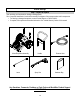
Initial Set-Up Step 1. Inspect & Unpack Upon receiving your item check for missing or damaged parts. See “Component Identification” section of this manual for a diagram of the pressure washer and its components. • For missing or damaged components, contact Product Support at 1-800-270-0810. • If complete, fill out product serial number information. See “Limited Warranty” section of this manual. Motor/Pump/Base Assembly Lance Handle Spray Gun Pressure Hose Hardware Bag Fig.
Initial Set-Up Hardware Bag Carriage Bolt Part# 82233 Qty-2 T-Handle Knob Part# 38578 Qty-2 Nylon Lock Nut Part# 777495 Qty-4 Flange- Nut Part# 82019 Qty-2 Gun Hook Part# 38509 Qty-1 Fig.
Initial Set-up Step 2. Assembly Step 3. Select Suitable Location Moving and Handling Note: Remove contents from packaging to begin assembly. WARNING Handle Assembly Lifting Hazard 1. Attach handle to bumper tube using: a. (2) Carriage Bolts (82233) b. (2) T-Handle Knobs (38578) 2. Spin a flange nut backwards onto gun hook. (See hook detail) 3. Mount the hose hooks onto the handle and gun hook onto the base as shown 4. Insert grommets into the holes on the handle nameplate. 5.
Grounding Instruction This product must be grounded. If it should malfunction or breakdown, grounding provides a path of least resistance for electric current to reduce the risk of electrical shock. This product is equipped with a cord having an equipment-grounding conductor and a grounding plug. The plug must be plugged into an appropriate outlet that is properly installed and grounded in accordance with all local codes and ordinances.
Operation Follow Safety Rules for Operation Instruct All Operators. The pressure washer's owner must instruct all operators and potential renters in safe set-up and operation. Do not allow anyone to operate the pressure washer who has not read the Owner's Manual and been instructed on its safe use. Adult Control only. Only trained adults should set up and operate the pressure washer. Do not let children operate.
Operation Preparing for Operation Never pull by hose. Do not move this pressure washer by pulling on the hose. Hose or connections could fail and result in catastrophic high-pressure release of fluid as well as hose whipping. Avoid sharp objects. Keep hose away from sharp objects. Bursting hoses may cause injury. No load bearing. Do not use the pump to support other items of equipment that impose unacceptable loads on the pump. Do not attempt to use this pressure washer as a prop.
Operation Inspect Spray System your garden hose. The bucket must fill faster than the times listed in the table below. Always inspect spray system for damage and leaks before each use. Do not start pressure washer until all needed repairs have been completed. Model# 990990 990991 WARNING High Pressure Fluid Injection Hazard High-pressure fluid discharge from leaks (even pinsized) or ruptured components can pierce skin and inject fluid into the body.
Operation 3. Release the collar, making sure it springs back and re-seats to its original (non-retracted) position. Check the connection by pulling on the hose to ensure a positive connection. Correct Insertion WARNING Depressurize First Any time you remove/install/change a nozzle, you must depressurize hose line by squeezing the spray gun trigger while the motor is off. Even if the motor has been off for a long period of time, the hose may remain dangerously pressurized.
Operation the nozzle at low pressure. (Air in the hoses can cause damage to the pump, so always make sure all the air is out of the hoses before starting the pressure washer motor.) • Make sure the water supply hose is not kinked. A kinked hose will provide insufficient water supply to the pump and reduce its life. Make sure the hose remains unkinked after moving the pressure washer. WARNING Chemical Spraying • Never spray acids, corrosives, or abrasive or flammable liquids.
Operation Begin High Pressure Spray Start-Up Procedures Start the Motor to Power the Pump 1. WARNING Make sure water supply is connected and primed. High - Pressure Spraying Safety CAUTION • Keep spray away from people. Never direct discharge stream at or near any person. Do not allow any part of the body to come in contact with the fluid stream. High-pressure spray can cause serious skin, eye, or falling injuries.
Operation Procedure: 1. Install the high-pressure spray nozzle (always relieve system pressure first and follow instructions for attaching a nozzle). WARNING Warranty Void Do not attempt to alter the unloader valve's maximum pressure. Excess pressure could cause serious injury from escaping high-pressure fluids and/or pump damage. Any alteration other than turning the adjustment knob will void your warranty. WARNING Injury This pressure washer is equipped with an On-Demand feature.
Storage When you are finished using the pressure washer, you must prepare the pressure washer for storage and store it in a proper location. • 12" piece of garden hose or equivalent, Funnel, and • approximately 6 oz. of RV antifreeze. 4. Attach the 12" garden hose piece with the funnel to the pump inlet. 5. Pour RV antifreeze into the funnel, then pull the recoil a few times until antifreeze comes out of the pump outlet.
Maintenance & Repair WARNING Maintenance Hazards ALWAYS shut off water supply, bleed water pressure, and turn off motor before cleaning, adjusting, or servicing the pressure washer. After servicing, make sure all guards and cover shields are replaced before using.
Maintenance & Repair 2. 3. 4. 5. WARNING High Pressure Fluid Injection Hazard High pressure fluid discharge from leaks (even pin-sized) or ruptured components can pierce skin and inject fluid into the body. Injection injury can result in blood poisoning and/or severe tissue damage leading to infection, gangrene, and possibly amputation. • • • • • Never use a finger or skin to check for leaks. Never operate pressure washer with damaged or missing hoses/parts.
Maintenance & Repair Change Pump Oil Change the pump oil after the first 50 hours of use, and then after every 3 months or 500 hours of use after that. 1. Remove drain plug from pump. 2. Drain pump oil into suitable container and dispose of responsibly. 3. Reinstall oil drain plug. 4. Make sure pressure washer is sitting level. 5. Reference the “Specifications” section of this manual to determine the oil type and quantity needed for your pump model. 6. Replace oil fill cap.
Troubleshooting The manufacturer reserves the right to make improvements in design and/or changes in specifications at any time without incurring any obligation to install them on units previously sold.
Parts Explosion- Model #990990, 990991 REV-D.
Parts List - Model #990990, 990991 ITEM # PART # 1 2 3 4 5 6 7 8 9 10 11 12 13 14 15 16 17 38509 802037 35198 802038 779761 38578 802039 788813 305200 38524 777915 777914 221222 777165 778147 791309 791308 778150 38530 2215 802096 778141 799485 794765 802311 792420 789205 777913 35918 800985 777855 5260 38527 780455 778070 778151 778152 777838 802097 18 19 20 21 22 23 24 25 26 27 28 29 30 31 32 33 DESCRIPTION Threaded Gun Hook NorthStar Decal 7/16 ID Grommet Handle Hose/Cord Hook T-Handle Knob Base Ti
Pump Assemblies – 4DX, 4DNX 7 6 1 8 3 4 Fig990990-5 2 4 5 Ref# 1 2 3 4 5 6 Part# 777913 800985 777340 777834 777165 802097 Description 3/8 QC NIPPLE X 3/8” NPT-MALE 3/8” INLET FILTER ¼” X ¼” HOSE BARB FITTING ¼” HOSE CLAMP ¼” PVC HOSE (SOLD BY FOOT) ON DEMAND FLOW SWITCH 7 35918 THERMAL VALVE 1 8 777838 1/4" NPT PLUG 1 28 Qty 1 1 1 2 1.
Pump Exploded View – Cat 4DX 29
Pump Parts List – Cat 4DX Ref# 5 8 10 11 15 20 24 25 27 32 33 37 38 48 49 53 64 65 70 90 98 99 100 106 120 121 125 160 P/N Not Available CA547153 CA14041 CA55337 CA14488 CA547048 Not Available Not Available CA15710 CA547961 CA14179 CA92241 CA44428 CA44842 CA14179 Not Available CA46229 CA132190 CA47215 CA542403 CA46730 CA542405 CA46233 CA48222 CA547357 CA13976 CA46240 CA13965 DESCRIPTION Screw Bearing Cover O-Ring, Bearing Cover Oil Seal Inner Ball Bearing Connecting Rod Oil Plug Cap Crankshaft Ball Bearin
Pump Exploded View – Cat 4DNX Ref# 5 8 10 11 15 20 24 25 27 32 33 37 38 48 49 53 64 65 70 90 98 99 100 P/N Not Available CA547153 CA14041 CA55337 CA14488 CA547048 Not Available Not Available CA15710 CA547961 CA14179 CA92241 CA44428 CA44842 CA14179 Not Available CA46229 CA542402 CA47215 CA547091 CA46730 CA542405 CA46233 DESCRIPTION Screw Bearing Cover O-Ring, Bearing Cover Oil Seal Inner Ball Bearing Connecting Rod Oil Plug Cap Crankshaft Ball Bearing Cap O-ring for Oil Filter Cap Gauge, Bubble Oil w/Gask
Wiring Diagram Model# 990990 Model# 990991 32
Limited Warranty Dear Valued Customer: The NorthStar Product you just purchased is built with the finest material and craftsmanship. Use this product properly and enjoy the benefits from its high performance. By purchasing a NorthStar product, you show a desire for quality and durability. Like all mechanical equipment this unit requires a due amount of care. Treat this unit like the high-quality piece of machinery it is. Neglect and improper handling may impair its performance.
CALIFORNIA PROPOSITION 65 INFORMATION WARNING: This product can expose you to soots, tars, and mineral oils (untreated and mildly treated oils and used engine oils), which are known to the state of California to cause cancer. For more information go to www.P65Warnings.ca.gov. Assembled by Northern Tool & Equipment Company, Inc. Burnsville, MN 55306 NorthernTool.