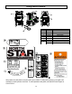
M157305AX ITEM NUMBER: 157305, 157306, 157307, 157308 SERIAL NUMBER: _____________ Owner’s Manual Electric Hot Water/Steam Pressure Washer Instructions for Set-up, Operation, Maintenance & Storage This pressure washer produces cold or hot water high-pressure spray as well as steam spray. Cleaning chemicals may be incorporated into the spray if desired. The pressure pump is powered by an electric motor and water is heated by an open flame burner fueled by diesel/kerosene or fuel-.
Table of Contents Equipment Protection Quick Facts ........................................................................................................................................ 1 TABLE OF CONTENTS ................................................................................................................................................ 2 ABOUT YOUR PRESSURE WASHER .........................................................................................................................
Spraying Procedure ............................................................................................................................................................ 17 Using Chemicals for Cleaning (if desired) ........................................................................................................................... 17 Hot Spray Procedure.................................................................................................................................................
About Your Pressure Washer Thank you for purchasing a NorthStar hot water pressure washer! It is designed for long life, dependability, and top performance. Site Selection. Pressure washers used while the open flame burner is used to heat the water are for OUTDOOR USE ONLY unless specific exhausting guidelines are met. Read additional details in the “Before Each Use” section of this manual. Intended Use.
Specifications MODEL Model # 157305 157306 157307 157308 FLOW OUTPUT Pressure Rating 1700 psi 2700 psi 2000 psi 2750 psi Flow Rate 1.5 gpm 2.5 gpm 1.5 gpm 2.5 gpm Maximum Temperature 250 F POWER REQUIREMENTS Dedicated NEMA Receptacles 5-20R 6-30R 5-20R 6-30R Volts 115V 230V 115V 230V Amps 20A 30A 20A 30A 385 lb. 415 lb. Hertz 60Hz Phase Single DIMENSIONS/COMPONENTS Length 38” Width 26” Height 43” Weight (fueled) 385 lbs. 415 lb.
Component Identification 1 5 6 2 12 19 16 7 11 17 3 16 4 13 14 18 15 10 8 9 1. 2. 3. 4. 5. Exhaust Vent: Provides an exit for burner exhaust gases. High Pressure Water Outlet: A passage for water to exit pump and enter the hose. Motor: Electric motor powers the pump. Burner: The oil burner is preset and performance tested at the factory. The Burner may need initial adjustment for peak performance. See “Oil Burner Adjustment” section for instructions on initial adjustment of the oil burner.
11. Power Switch: Flip up for on. 12. Thermostat: Controls power to fuel solenoid for firing. 13. Control Panel: Power Switch (Reference 15), Thermostat (Reference 16) and Nozzle Storage (Reference 18) are located on control panel. 14. Nozzle Storage: Control Panel (Reference 17) has space for storing nozzles. 15. Fuel Filter/Water Separator: Filter in fuel line that removes water and screens out dirt and debris from fuel. 16. Power Cord Hangers: Storage Location 17.
Special Equipment Safety Features Pump Thermal Relief Valve This unit is equipped with the following safety features: This valve, on the Unloader bypass port, protects the pump from overheating. The pump continues to work in bypass mode when you are not spraying. If high temperatures are developed during bypass mode, the Thermal Relief Valve will open and discharge hot water onto the ground, protecting the pump from overheating. High Pressure Safety Device (Rupture Disc) Acts as a backup safety feature.
Safety Hazard Signal Word Definitions This is the safety alert symbol. It is used to alert you to potential personal injury hazards. Obey all safety messages that follow this symbol to avoid possible injury or death. DANGER (red) indicates a hazardous situation, which if not avoided, will result in death or serious injury. DANGER WARNING (orange) indicates a hazardous situation, which if not avoided, could result in death or serious injury.
Safety Decal Locations ® CHEMICAL NOZZLE 0° NOZZLE Ref# 1 2 3 4 5 6 7 8 15° NOZZLE STEAM NOZZLE 25° NOZZLE 40° NOZZLE Part# 305410 777725 305427 778176 778174 778070 N/A 798057 32821 Description Caution, Hot Water NorthStar Danger, Hot Water Control Panel Nozzle Cord Warning Warning/Start-Up Instructions Rupture Disk Warning TFG Lanyard Part No. 778070 0° NOZZLE 15° NOZZLE STEAM NOZZLE 25° NOZZLE 40° NOZZLE RISK OF ELECTROCUTION 1.
Assembly and Initial Set-Up Step 1. Inspect & Unpack Step 2. Assembly Inspect pressure washer immediately after delivery for missing parts or damage. Find and separate components identified in Figure 4 and Figure 5. Insert nozzles in spaces provided on the control panel. To install wheels, refer to Figure 6: • Raise pressure washer off floor using blocks or ramps and secure. • Install two wheels with grease zerk away from frame. • Slide wheel retainers onto end of each axle.
Handle (NFPA 70) and to provide additional protection from the risk of electric shock. Note: Before use, your GFCI should be tested at either built-in or receptacle base. 1. For a product rated at 125 volts or less, the GFCI is built into the power cord plug. • This GFCI device provides additional protection from the risk of electric shock. If replacement of the plug or cord is needed, use only identical replacement parts. 2. For a product rated at more than 125 volts, a receptacle based GFCI is required.
Before Each Use Follow the steps below prior to each use. WARNING: High pressure fluid injection hazard Step 1: Inspect Equipment Electrical • • • • • High-pressure fluid discharge from leaks (even pinsized) or ruptured components can pierce skin and inject fluid into the body. Injection injury can result in blood poisoning and/or severe tissue damage leading to infection, gangrene, and possibly amputation. Inspect cord before using. Do not use if cord is damaged.
Filling Burner Fuel Tank (if heated water to be used) Step 3. Select Suitable Worksite Guidelines WARNING: Location hazard WARNING: Flammability hazard You must choose a suitable site for operating your pressure washer to avoid equipment damage and/or injury and possible death from carbon monoxide poisoning, fire/explosion, uncontrolled equipment movement/tip over, or slips and falls.
For Indoor Hot Water/Burner Use For more details, refer to NFPA 31: Standard for the Installation of Oil-Burning Equipment. Chapter 5 provides guidelines on how to ensure adequate air is provided for safe combustion. • Exhaust: • Hot fumes from burner must be exhausted through a hood or piped to the outside. • Place the unit so that the exhaust fumes will not be directed towards people or building air intakes. Precautions: • Keep a fire extinguisher rated “ABC” nearby.
Figure 10 Coupler Turn pressure washer off and depressurize line before connecting a new nozzle. Engage safety latch on spray gun. Connect appropriate nozzle according to “Quick Connect Procedure.” Water outlet or nozzle-type connection Collar Step 2. Pre-Spraying Procedure Safety Rules Figure 9a Correct Insertion Not Fully Inserted Collar Seated Collar NOT Seated Figure 9b Prevent slips/loss of balance.
Personal Protective Gear • WARNING: High pressure spray hazard • High-pressure spray can injure eyes/skin. Hot water can burn. Flying objects and debris can cause injury. Serious injection injury can result if high-pressure spray penetrates the skin.
Chemical Spraying Procedure: • Disengage safety latch and apply chemicals evenly to the cleaning surface working from bottom upward, using long, even, and overlapping passes. • Allow chemicals time to react with dirt before rinsing. Do not allow the chemical to dry on, reapply as needed to prevent surface from drying. Rinsing: • Change to a high-pressure nozzle for rinsing. Changing to a high-pressure nozzle will automatically stop the flow of chemicals into the water stream.
Step 4. Stopping DANGER: Carbon monoxide poisoning hazard If the heater was used, turn heat switch OFF and run cold water through the coil for at least 2 minutes while spraying. If no heater, you may immediately: • Turn power switch OFF. • Turn water supply OFF. • Actuate spray gun trigger to relieve system pressure. • Remove garden hose, pressure hose and nozzle • Unplug pressure washer. • Let machine cool for 5 minutes and store in a clean, dry area until next use.
Maintenance & Repair WARNING: Maintenance hazards ALWAYS shut off water supply, bleed water pressure, turn off motor and unplug electrical cord before cleaning, adjusting, or servicing the pressure washer. After servicing, make sure all guards and cover shields are replaced before using. Follow all safety rules and recommended maintenance instructions. If a part needs replacement, only use factory approved repair parts.
b. For Cat pumps: Use SAE30 non-detergent oil or Cat Pump Oil Item #22158. • Replace oil fill cap. Drain Burner’s Fuel Filter/Water Separator Good Water dripping or spraying, or localized moisture Exposed wire mesh due to wear • • • Drain water from burner’s filter bowl as needed. Replace filter after every 500 hours of use or annually. • Important: Always empty the burner’s fuel tank before removing the filter bowl. • Check the filter bowl after each use of burner.
• • • • • Attach high-pressure hose(s) to machine’s highpressure water outlet. Do not hook up the spray gun. Place other end of high-pressure hose(s) in the 5gallon bucket. Attach a short length of garden hose to garden hose inlet on the pump. Prime pump by filling short garden hose with water (a funnel will work), then placing end of hose in the bucket. Run pressure washer in cold mode for 1 to 3 hours, recirculating the cleaning solution.
8) Insert the “Shuttle Assembly” with the rounded end first, into the body. Align with grooves. 4) Observe the “Shuttle Assembly” and internal portion of “Body” for obstructions, hard water deposits and any other foreign debris. Remove the foreign debris with light scraping or compressed air. If no additional cleaning is required continue to Step 7. If additional cleaning is required continue to step 5.
Inspect Heating Coil and Desoot as Needed Inspect and desoot coil annually. Although most coils never require desooting, poor grades of fuel oil or inadequate combustion air will cause heavy soot buildup on the outside surface of the heating coil tubing. These deposits will insulate the coil, which then restricts airflow through the heat exchanger and further aggravates the soot build-up.
NorthStar Product Support will assist in these repairs as needed, but if an inoperable pressure washer creates a major expense to your business, then we strongly recommend the following: Electrodes Have a staff person become familiar with the mechanical operation of the pressure washer and capable of making minor repairs and performing all preventative maintenance procedures. • Keep a stock of recommended service parts for maintenance and minor repairs.
Oil Burner Adjustment (only needed if white exhaust smoke appears) Figure 24 The oil burner is preset and performance tested at factory elevation of 1100 feet. Different altitudes may require a one-time initial burner adjustment. 5. Loosen locking screw and rotate air band closed until black smoke appears from burner exhaust vent. Note which number arrow points to. 6. Slowly open air band until white smoke just starts to appear. 7. Turn air band halfway back to black smoke position previously noted.
Troubleshooting Pressure Washer Will Not Run At All - No Power Causes Solutions Machine turned OFF Line circuit breaker tripped Turn Pump switch ON Check for tripped circuit breaker in building Circuit Breaker Trips Causes Voltage too low Circuit Breaker Overloaded Pressure set too high Solutions Check the voltage Make sure there is no other equipment using the same circuit. Check/adjust pressure setting on unloader.
Parts Explosion– Rev AX 28
Parts List– Rev AX ITEM PART # DESCRIPTION QTY MODEL ALL ALL ALL ALL ALL ALL ALL ALL ALL ALL ALL ALL ALL ALL ALL ITEM PART # 1 2 3 6 7 8 9 10 11 12 13 15 16 17 18 38525 777914 777915 791274 791278 780455 779168 22622 38398 785937 35331 777913 30048 305208 785933 50’ PW Hose Assembly Quick Couple, 3/8” FPT Quick Couple Nipple, 3/8” FPT Quick Coupler, 1/4” FPT Lance Assembly Quick Couple, 3/8” FPT Gun Trigger Assembly Gun Grip, 18 in.
Pump Explosions ITEM 2 PART # 790693 790550 792420 789205 35918 DESCRIPTION Comet AXD 1617E GH Comet AXD 2527GE-NH Cat 4DX Cat 4DNX Thermal Protector, 1/4” 6 777837 3/8" Plug 1 7 777411 3/8” Tee 1 8 800985 Filter, Inlet, 3/8" NPT X 3/4" FGH 1 9 777838 Plug, Hex 1/4” 1 1 30 QTY 1 1 1 1 1 MODEL 157305 157306 157307 157308 157307, 157308 157307, 157308 157307, 157308 157307, 157308 157307 157308
Comet AXD 1617E GH Pump Exploded View 31
Comet AXD 1617E GH Pump Exploded View Part # Ref # 1 CO3202001800 Description Qty Ref # Part # CAP 1 39 CO3200001700 Description Qty 2 CO3609001400 SCREW, M8 X 55 4 40 CO2409009100 3 4 CO3218032700 CO3202001800 1 1 41 42 CO1210046000 CO2409008600 5 CO1210004900 6 43 CO1802019700 SPRING 1 6 SEE PART # 10 MANIFOLD CAP O-RING,OIL PLUG - WOBBLE PUMP VALVE SEAT PORT PLUG, AXD COMET PUMP PISTON CHECK VALVE KIT,AXD UNL O-RING CHECK VALVE 6 44 CO3410031900 1 7 CO3604002800 SUC
Comet AXD 2527GE-NH Pump Exploded View 33
Comet AXD 2527GE-NH Pump Exploded View Part # Ref # 1 CO3202001800 Description Qty Ref # Part # CAP 1 39 CO3200001700 Description Qty 2 CO3609001400 SCREW, M8 X 55 4 40 CO2409009100 3 4 NOT AVAILABLE CO3202001800 1 1 41 42 CO1210046000 CO2409008600 5 CO1210004900 6 43 CO1802019700 SPRING 1 6 SEE PART # 10 MANIFOLD CAP O-RING,OIL PLUG - WOBBLE PUMP VALVE SEAT PORT PLUG, AXD COMET PUMP PISTON CHECK VALVE KIT,AXD UNL O-RING CHECK VALVE 6 44 CO3410034800 1 7 CO3604002800 S
Cat 4DX Pump Exploded View 35
Cat 4DX Pump Exploded View Ref# 5 8 10 11 15 20 24 25 27 32 33 37 38 48 49 53 64 65 70 90 98 99 100 106 120 121 125 160 P/N Not Available CA547153 CA14041 CA55337 CA14488 CA547048 Not Available Not Available CA15710 CA547961 CA14179 CA92241 CA44428 CA44842 CA14179 Not Available CA46229 CA132190 CA47215 CA542403 CA46730 CA542405 CA46233 CA48222 CA547357 CA13976 CA46240 CA13965 DESCRIPTION Screw Bearing Cover O-Ring, Bearing Cover Oil Seal Inner Ball Bearing Connecting Rod Oil Plug Cap Crankshaft Ball Beari
Cat 4DNX Pump Exploded View Ref# 5 8 10 11 15 20 24 25 27 32 33 37 38 48 49 P/N Not Available CA547153 CA14041 CA55337 CA14488 CA547048 Not Available CA549446 CA56084 CA547961 CA14179 CA92241 CA44428 CA44842 CA14179 DESCRIPTION Screw Bearing Cover O-Ring, Bearing Cover Oil Seal Inner Ball Bearing Connecting Rod Oil Plug Cap Crankshaft Ball Bearing Cap O-ring for Oil Filter Cap Gauge, Bubble Oil w/Gasket Gasket, Flat Flex Oil Gauge Drain Plug O-Ring for Drain Plug QTY 3 1 1 1 1 3 1 1 1 1 1 1 1 1 1 53 64
Wiring Diagrams 38
Wiring Diagrams 39
Wiring Diagrams 40
Wiring Diagrams 41
Wiring Diagrams 42
Limited Warranty Dear Valued Customer: The NorthStar Product you just purchased is built with the finest material and craftsmanship. Use this product properly and enjoy the benefits from its high performance. By purchasing a NorthStar product, you show a desire for quality and durability. Like all mechanical equipment this unit requires a due amount of care. Treat this unit like the high quality piece of machinery it is. Neglect and improper handling may impair its performance.
WARNING: This product can expose you to chemicals including acetaldehyde, which is known to the State of California to cause cancer, and carbon monoxide, which is known to the State of California to cause birth defects or other reproductive harm. For more information go to www.P65Warnings.ca.gov. Manufactured by Northern Tool + Equipment Co., Ltd Burnsville, MN 55306 NorthernTool.