
Installation Instructions

MANUFACTURED BY
NORWECO, INC.
NORWALK, OHIO
U.S.A. 44857
www.norweco.com
©MMXVIII NORWECO, INC. NORWALK, OHIO U.S.A.
INSTALLATION THE OF BIO-KINETIC
®
SYSTEM (Cont.)
MOLDED LOCKING SLOTS
water immediately after backlling has been completed
to prevent damage to the Singulair Green tank. The
aeration and clarication chambers will both be lled
if the hose is installed in the aeration chamber access
opening. The pretreatment chamber should be lled
separately through its access opening.
5. Inuent and euent sewer lines must be installed
and connected to the system as soon as it is set and
before backlling to prevent entry of mud or debris.
Follow the procedures outlined in the Singulair Green
Tank Delivery and Setting instructions when backlling
the installation. Failure to follow proper backlling
procedure may result in damage to the tank and will
void the Singulair Green warranty.
6. When a Singular Green system is being installed to
replace a failed onsite wastewater treatment system,
the old septic tank need not be abandoned. However,
be sure the Singulair Green system is installed
downstream of the old septic tank and that the entire
obsolete system is completely pumped and cleaned
before the Singulair Green tank is installed. If the
owner prefers, the obsolete system may be totally
removed or lled in and abandoned in the ground.
7. Check to see that roong down spouts, footer drains,
sump pump piping or garage and basement oor drains
are not connected to the sanitary sewer. The Singulair
Green system may not operate properly if hydraulic
ows greatly exceed the rated treatment capacity. If the
facility is equipped with a water softener, locate the
backwash discharge line. The backwash line must not
be connected to the Singulair Green system.
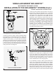
BIO-KINETIC SYSTEM INSTALLATION PROCEDURE
Remove the Bio-Kinetic system from the shipping carton.
Lift o the Bio-Kinetic system service cover and set it
aside. Rotate the round, black locking lugs inward to allow
installation.
The Bio-Kinetic system discharge ange must engage
the plastic receiving ange that has been installed in the
outlet of the Singulair Green tank. Carefully examine the
condition of the outlet coupling and receiving ange. Any
residue or debris that has accumulated in the grooves of
the receiving ange must be removed and the grooves
and face of the receiving ange should be wiped clean.
Use the swab tool to apply a liberal amount of Bio-Kinetic
lubricant to the entire face of the receiving ange and the
inside of the grooves. Apply the lubricant evenly until all
interior surfaces of the receiving ange and the grooves are
thoroughly coated. Locate the gasketed discharge ange
assembly installed in the outlet of the Bio-Kinetic system.
Check to make sure that the assembly is tight and fully
engages the discharge opening of the Bio-Kinetic system.
Using the swab tool, apply a liberal amount of lubricant to
the exterior surfaces of the gasketed discharge ange.
Apply the lubricant evenly over the entire face of both sides
and along the edges of the discharge ange.
CAUTION: Bio-Kinetic lubricant has been specially
formulated. Use of other lubricants, especially
petroleum based lubricants, can cause degradation
of the rubber components and will void the warranty.
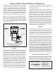
SELF FILL VALVE
Use the lifting tool to lower the Bio-Kinetic system into
the mounting riser. Be careful to align the discharge ange
with the receiving ange installed in the outlet of the tank.
The Bio-Kinetic system is equipped with a pressure sensitive
valve to aid in the lling process for new systems that are not
yet lled and the draining process during service or removal.
The ll valve is engineered to open when the pressure
outside the Bio-Kinetic system reaches 16" of head. When
the tank water level reaches 16" on the outer chamber of an
empty Bio-Kinetic system, the ll valve will open. The valve
will remain open until the water level inside the lter reaches
4" below the water level outside the lter. At this point, the
valve will close. For instructions on the drain valve system,
refer to “Clarication Chamber and Bio-Kinetic Service.”
Carefully guide the system through the center of the opening
using the lifting tool. Be sure to maintain the Bio-Kinetic
system in a vertical position. If tilted, the system could rub
the edge of the opening and be damaged. NOTE: Use the
viewing port to be sure proper alignment and engagement
of the outlet connection takes place. The discharge ange