
Installation Guide

For assistance call 800-522-7336 Monday through Friday 7am to 6pm Mountain Time
PK173 9202017
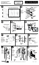
17
18
22
24
21
13A
14
26
25
9
10
12
16
15
14
1
3A
4
5
6
8
7
23
3C
3B
1A
13
19
20
11
2
1.
Deadbolt Latch
1A.
Latch Tongue
2.
3/4″ Latch & Strike Wood Screws (8)
3.
Cylinder Assembly (W/Keys)
3A.
Cylinder Body
3B.
Tailpiece
3C.
Spin Ring
4.
Plate
5.
Deadbolt Adapter Plate
6.
7.
Thumbturn Assembly
8.
5/8″ Thumbturn Machine Screws (2)
9.
Dustbox for Deadbolt
10
Door Frame Reinforcer
11.
3″ Reinforcer Wood Screws (2)
12.
Strike Plate for Deadbolt
13.
Handleset Latch
13A.
Latch Tongue
14.
Latch Faceplate
15.
Handleset Spindle
16.
Exterior Handleset
17.
Adapter Plate
19.
Long Plate
18.
Adapter Plate Screws (2)
20.
1″ Plate Mounting Screws
21.
Knob
22.
Screw Cover Adapter
23.
24.
Mounting Screw Cover
25.
Dustbox for Handleset
26.
Strike Plate for Handleset
}
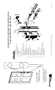
3
Cross-Bore
Holes
Edge-Bore
Holes
Part
Number
Part
Description
Exploded Drawing Single Cylinder Handleset
Long Plate With Pre-Attached Knob
2” Machine Screws (2) for 1-3/4” thick
doors. 2-1/4” Machine Screws (2) for
2” thick doors.
2-1/2″ Bottom Grip Mounting Screw for
1-3/4” thick doors. 2-3/4” for 2” thick doors.
A
A
B
B
Push plastic template’s
large circles (A) into
existing bore holes of door.
Use position of bottom hole (B)
to mark and drill 1/4 inch
bottom grip mounting hole.
1.
2.