
Instructions / Assembly


Interior Cylinder Exterior Cylinder
Step 5 - Install the Deadbolt
“Outside” Half
A) Using Figure #1 for reference, gather together both cylinder
assemblies (Part #4 & #6), both spin rings (Parts #5A), both
deadbolt escutcheons (Parts #5B), security ring (Part #16) and
2-3/4” machine screws (Part #7). Note: Not all designs use
spin rings. If your escutcheon is a Newport or Georgetown
design, then no spin ring is required. Except in rare cases such
as split finish designs, the interior and exterior escutcheons
will be interchangeable.
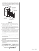
B) Locate the exterior cylinder assembly, see Figure #5. This
can easily be identified by the Grandeur logo on it. Note: If
your design requires a spin ring, place the cylinder bar (Part
#4A) end of the cylinder assembly (Part #4) through the spin
ring, making sure that the narrower diameter of the spin
ring is closest to the key hole end of the cylinder assembly.
Next, insert the cylinder assembly (with spin ring if required)
through the deadbolt escutcheon (Part #5B) and finally add
the security ring as seen in Figure #6.
C) From the outside of the door, insert the cylinder bar (Part
#4A) through the “+” in the deadbolt latch housing. Make
sure that the cylinder bar is oriented as shown in Figure
#7A or Figure #7B and that the deadbolt is still extended
from the edge of the door. From the inside of the door, if the
deadbolt extends toward the right, then the cylinder bar needs
to be oriented vertically Figure #7A. If the deadbolt extends
toward the left, then the cylinder bar needs to be oriented
horizontally, Figure #7B. IMPORTANT: If this step is not
done correctly, then the deadbolt will not work correctly!
Step 3
Mortise for the Faceplate
A) Using Figure #1 for reference, find the deadbolt faceplate
(Part #2). On the edge of the door, center the deadbolt
faceplate over the newly drilled edge bore hole, so that the
large hole in the deadbolt faceplate is centered over the 1”
edge bore hole. Align it so that the edges are parallel to the
edges of the door and roughly centered side-to-side. Mark
around the deadbolt faceplate with a pencil and remove from
door.
B) Using the chisel, score the outline of the deadbolt faceplate.
Next, chisel away the material within the outline to a depth
of 1/8”. When you are done, you should be able to insert the
deadbolt latch (Part #1), place the deadbolt faceplate over
the extended deadbolt (Part #1A), and have the deadbolt
faceplate be flush with the edge of the door.
C) Again, using the deadbolt faceplate as a template and the
awl as a marking tool, mark for the two screw holes that will
hold the deadbolt faceplate on the door. Remove the deadbolt
faceplate from the door to avoid marring the finish. Then,
drill the two screw holes using a 7/64” drill bit. Make sure the
holes are drilled at least 1” deep. Having too shallow a hole
can cause the screws to shear off.
Installing Your Lock
Step 4
Install the Latch
A) Insert a screwdriver into the deadbolt latch housing (Part #1)
and extend the deadbolt. Insert the deadbolt latch into the
edge bore hole, making sure that the “+” is oriented towards
the lower edge or bottom side of the deadbolt latch, see
Figure #4.
B) Add the deadbolt faceplate over the deadbolt latch and make
sure that it can sit flush in the mortised out area. Note: Some
doors come prepared with rounded corners in the mortised-
out area. If your door is prepared like this, simply use a chisel
to square off the corners so that the faceplate lies flush with
the edge of the door.
C) Install the 3/4” latch & strike wood screws (Part #3) to hold
the deadbolt latch and deadbolt faceplate in place.
Page 2 - PK158
Figure #4
Figure #5
Figure #6