
Instructions / Assembly


D) Make sure that the cross bore hole will be completely covered
by the outside escutcheon and that the Grandeur logo is
oriented correctly.
“Inside” Half
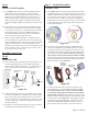
E) Locate the interior cylinder assembly (Part #6). This can
easily be identified because it has two holes drilled through
the face of the cylinder, see Figure #5. Assemble the interior
cylinder assembly and escutcheon as outlined in Step 5B.
F) Rotate the interior cylinder bar so that it is oriented in the
opposite orientation that you used in Step 5C. Holding the
exterior half of the deadbolt on the door, install the interior
half of the deadbolt. The driver bars will mate together in
the hub of the deadbolt latch. Depending on the thickness of
your door, the interior and exterior should be able to sit flush
against the door. If they do, go to Step 5I.
G) Adjustments must be made for thinner doors where the
deadbolt cannot sit flush against the door. Remove the interior
half of the deadbolt and set it aside. Holding the exterior half
in place, observe how much of the cylinder driver bar (Part
#4A) sticks through the latch, see Figure #7A & #7B. The
tangs on the driver bar are scored with marks to make this
easier. Count the marks showing through on a single tang and
if desired, mark the tang using a marker. Remove the exterior
half of the deadbolt. Using wire cutters, carefully snip off the
tangs at the last mark that was visible when it was installed
through the latch, being careful not to bend the tangs.
Reinstall the exterior half of the deadbolt to verify that the
tangs have been cut to the length which only leaves a small
amount still protruding from the latch. Follow these same
steps for the inside cylinder assembly.
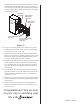
H) Reinstall the deadbolt parts as outlined in Steps 5C - 5F. The
spin ring (or round escutcheon for Newport and Georgetown
designs) on the inside of the door, must be oriented with the
escutcheon slots at the 1 o’clock, 5 o’clock, 7 o’clock and 11
o’clock positions, a shown in Figure #8.
I) Locate the two 2-3/4” machine screws (Part #7). While
holding both the interior and exterior halves in place, insert
the machine screws through the interior cylinder assembly.
The screws will go through the latch and into the back
of the exterior cylinder assembly. Slowly screw in the
machine screws until nearly snug. Align the escutcheons for
appearance and fully tighten the screws.
J) Insert, turn, and remove the key in each side to make sure that
the deadbolt operates smoothly. If not, loosen the screws and
realign the escutcheons. With the screws not fully tightened,
turn the key on each side of the door to determine if both
sides operate smoothly. If only one side operates smoothly,
it is likely that the cylinder assembly driver bar tangs are too
long coming from the other side and are rubbing on the back
of the cylinder assembly. Using the wire cutters, trim them
back slightly and see if this fixes the issue. If not, call or
customer service department at 800-522-7336 for assistance.
K) Once you have tested the action of the deadbolt and it is
acceptable, move on to Step 6.
Step 6
Install the Interior Cylinder Faceplate
IMPORTANT: Before moving on to Step 6 it is critical that you
verify that the deadbolt is working properly. Insert the key
and turn it to both the locked and unlocked position and
remove the key in each position. Then repeat this for the
opposite side of the door. Only once you are satisfied with the
smooth operation of the deadbolt should you proceed.
A) Locate the interior cylinder faceplate (Part #8) and the plastic
faceplate jig (Part #9). Place the faceplate on the interior
cylinder, such that the logo and hole for the key align with the
cylinder. There are slots cut into the spin ring or escutcheon
that the tabs on the edge of the faceplate will align with, see
Figure #8.
B) Once the faceplate is aligned correctly, place the plastic
faceplate jig over the faceplate and press the faceplate into
position. Important: The faceplate must be pressed into place
evenly in order to avoid bending the faceplate. In most cases,
you will need to lightly tap the faceplate jig with a rubber
mallet or hammer to seat the faceplate properly.
Step 7
Installing the Door Reinforcer and Strike
Note: If door jamb is already drilled, go to Step 7E below.
A) With the deadbolt in the unlocked position, close the door.
From the inside of the house, turn the key and identify where
the bolt is contacting the door jamb. Lightly mark this with
a pencil on the door jamb. Measuring in from the door stop
trim, identify the center mark where the bolt hole needs to
Page 2 - PK158
Page 3 - PK158
Figure #7A
Figure #8
Figure #
7B
Inside of Door
Deadbolt extends right
Inside of Door
Deadbolt extends left