
Installation & Assembly


Step 5
Install the “Outside” Half of the Deadbolt
A) Using Figure #1 for reference, gather together the cylinder
assembly (Part #4), spin ring (Part #5A), the outside
escutcheon (Part #5B), the deadbolt adaptor plate (Part #7)
and two 1-1/4″ machine screws (Part #8).
B) Place the spin ring over the cylinder driver bar (Part #4A)
end of the cylinder, making sure that the narrower edge of
the spin ring is closest to the key hole end of the cylinder.
Insert the cylinder through the spin ring and escutcheon to
make the outside assembly complete, see Figure #5.
C) From the outside of the door, insert the cylinder driver bar
(Part #4b) through the “+” in the latch housing, making sure
that the driver bar is oriented vertically with the latch
bolt extending from the edge of the door.
D) Make sure that the cross bore hole will be completely covered
by the outside escutcheon and that the Nostalgic Warehouse
logo is oriented correctly.
E) On the inside of the door, place the adaptor plate so that the
beveled screw holes face away from the door and line up
with the cylinder posts. Screw on the two 1-1/4″ machine
screws to hold the outside assembly in place, see Figure #6.
Do not tighten yet.
F) Align the outside escutcheon and cylinder with the door
edge and snug the two 1-1/4″ machine screws down. Do not
overtighten.
G) Using the key, unlock and re-lock the latch to make sure that
the action is smooth. If the screws have been over tightened,
the latch may bind. Once the action is acceptable, move on to
Step 6.
Step 3
Mortise for the Faceplate
A) Using Figure #1 for reference, nd the faceplate (Part #2). On
the edge of the door, center the faceplate over the newly drilled
edge bore hole, so that the D-shaped hole in the faceplate is
centered over the 1″ edge bore hole. Align the faceplate so
that the edges are parallel to the edges of the door and roughly
centered side-to-side. Mark around the faceplate with a pencil
and remove from door.
B) Using the chisel, score the outline of the faceplate. Next,
chisel away the material within the outline to a depth of 1/8″.
When you are done, you should be able to insert the latch
(Part #1) into the edge bore hole, place the faceplate over the
latch tongue (Part #1A), and have the faceplate be ush with
the edge of the door.
C) Again, using the faceplate as a template and the awl as a
marking tool, mark for the two screw holes that will hold the
faceplate on the door. Remove the faceplate from the door
to avoid marring the nish. Then, drill the two screw holes
using a 7/64″ drill bit. Make sure the holes are drilled at least
1″ deep. Having too small or too shallow a hole can cause the
screws to shear off.
Installing Your Lock
Step 4
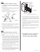
Install the Latch
A) Insert a screwdriver into the deadbolt latch housing (Part #1)
and extend the deadbolt (Part #1A). Insert the deadbolt latch
into the edge bore hole, making sure that the “+” is oriented
towards the lower edge or bottom side of the deadbolt latch,
see Figure #4.
B) Add the deadbolt faceplate (part #2) over the deadbolt latch
and make sure that it can sit ush in the mortised out area.
Note: Some doors come prepared with rounded corners in
the mortised-out area. If your door is prepared like this,
simply use a chisel to square off the corners so that the
faceplate lies ush with the edge of the door.
C) Install the 3/4” latch & strike wood screws (Part #3) to hold
the deadbolt latch and deadbolt faceplate in place.
Figure #5
Figure #6
hv/RIENTEDONTHE
LOWEREDGE
$EADBOLT,ATCH
0ART
%XTENDED
$EADBOLT
0ART!
$EADBOLT
&ACEPLATE
0ART
v,ATCH3TRIKE
7OOD3CREWS
0ART
%DGE"ORE
(OLE
Figure #4
Page 2 - PK133