AirStrand 1300 Installation Guide Part Number: DUG01370-SP System Release: 15.
© Copyright by Airspan Networks Inc., 2020. All rights reserved worldwide. Legal Notices The information contained within this document is proprietary and is subject to all relevant copyright, patent and other laws protecting intellectual property, as well as any specific agreements protecting Airspan Networks Inc. rights in the aforesaid information.
Table of Contents Document Information ............................................................................... 1 Abstract .................................................................................................................. 1 Revision History ..................................................................................................... 1 Warnings and Cautions ............................................................................. 2 Human Exposure to Radio Frequencies .....
AirStrand 1300 Installation Guide Document Conventions ........................................................................................ 11 Related Reading .................................................................................................. 12 Customer Care Help Desk ......................................................................13 Airspan Encourages Comments .......................................................................... 13 1 Introduction ..........................
AirStrand 1300 Installation Guide C Abbreviations .......................................................................................32 Figures Figure 1: AirStrand 1300 .................................................................................................................. 10 Figure 2: AirStrand 1300 .................................................................................................................. 15 Figure 3: Workflow..........................................................
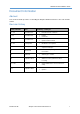
AirStrand 1300 Installation Guide Document Information Abstract This document details procedures for installing the Airspan’s AirStrand 1300 Pico-class LTE eNodeB variant. Revision History Revision Details Date 0.1 – 0.
AirStrand 1300 Installation Guide Warnings and Cautions Human Exposure to Radio Frequencies The AirStrand 1300 when operational should be operated from a minimum safe distance of 50cm (19.7in). Avertissement et Precautions d’Utilisation Exposition des personnes aux fréquences radioélectriques Les antennes d’AirStrand 1300 quand opérationnel doivent être installée et utilisée de façon à garantir la distance minimale de sécurité de 50cm (19.7in).
AirStrand 1300 Installation Guide Général Seul le personnel qualifié peut être autorisé pour installer ou remplacer l’équipement ainsi qu’effectuer les opérations de maintenance pour cet équipement. L’équipement ne peut pas être vendu en grande distribution ou par commande via email à destination du public. Il doit être vendu aux opérateurs de télécommunications. Son installation doit être contrôlée Son Installation doit être effectuée par des professionnels autorises.
AirStrand 1300 Installation Guide 9. The radio transceiver must be properly grounded to protect against power surges and accumulated static electricity. It is the user’s responsibility to install this device in accordance with the local electrical codes. 10. Installation of the AirStrand 1300 must be contracted to a professional installer. 11. The circuit breaker should be easily accessible in case you have to disconnect the device. 12.
AirStrand 1300 Installation Guide 1990). At the end of any Airspan products life cycle, the customer should consult with Airspan to ensure that the product is disposed of in conformance with the relevant regulatory requirements. Attention aux Voltages Hasardeux Sur les installations de réseau électrique de type courant alternatif (CA), des voltages hasardeux peuvent survenir. Garder une Attention particulière lors d’une vérification ou de travaux sur réseau électrique CA.
AirStrand 1300 Installation Guide Refer all repairs to qualified service personnel. Do not modify any part of this device, as this will void the warranty. Disconnect the power to this product and return it for service if the following conditions apply: a. The terminal does not function after following the operating instructions outlined in this manual. b. The product has been dropped or the housing is damaged.
AirStrand 1300 Installation Guide DECLARATION OF CONFORMITY European Community, Switzerland, Norway, Iceland, and Liechtenstein Declaration of Conformity with Regard to the R&TTE Directive 1999/5/EC English: This equipment is in compliance with the essential requirements and other relevant provisions of Directive 1999/5/EC. Deutsch: Dieses Gerät entspricht den grundlegenden Anforderungen und den weiteren entsprecheneden Vorgaben der Richtlinie 1999/5/EU.
AirStrand 1300 Installation Guide GPS Compliance The GPS is in compliance with the essential requirements and other relevant provisions of Directive 1999/5/EC.
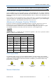
AirStrand 1300 Installation Guide Maximum Output TX Total Power Table 1: AirStrand 1300 B48 FCC Maximum Output TX Total Power Frequency Band (MHz) 3550 – 3700 TX (dBm) 10 MHz BW: Pout=27.59 20 MHz BW: Pout=27.95 FCC Antenna Gain (dBi) EIRP (dBm) 10 MHz BW: Pout=38.59 20 MHz BW: Pout=38.95 11 Note: The AirStrand 1300 requires operation using an Airspan FCC-specific version of Netspan acting as a CBRS Domain Proxy. Caution: Do not set maximum output TX power to higher than local regulations.
AirStrand 1300 Installation Guide Antenna System The eNB solution is based on a dual sector model that can be operated as a dual sector / dual carrier mode of operation. There are 4x directional 2x2 antennas which are positioned perpendicular to the strand (back to back) and along the strand.
AirStrand 1300 Installation Guide About This Document Purpose This guide provides the workflow and step-by-step procedures for Installing the AirStrand 1300. These procedures include: Verify prerequisites Assemble Strand Brackets on Unit Install the AirStrand 1300 Connect and manage cables Intended Audience This guide is intended for persons who are responsible for installing the AirStrand 1300 equipment. These persons should have a working knowledge of the equipment.
AirStrand 1300 Installation Guide Related Reading The following documents contain related information: AirStrand 1300 Hardware Product Specification Pending Airspan LTE Commissioning Manual Pending DUG01370-SP Airspan Commercial and Internal Use 12
AirStrand 1300 Installation Guide Customer Care Help Desk Airspan’s Customer Care Help Desk offers prompt and efficient customer support services. Note: To avail Airspan’s Customer Care Help Desk support, you must be a registered user and must have a valid support contract. To register, click here and fill the Registration form. To create and update issue logs, send e-mails to Customer Care Help Desk. Once you submit your issue, the system generates a new issue and sends an issue number for your reference.
AirStrand 1300 Installation Guide 1 Introduction This section provides a descriptive overview of the Airspan’s AirStrand 1300 Pico-class eNodeB variant and its place in the Airspan product suite. 1.1 AirStrand 1300 AirStrand 1300 is part of Airspan’s carrier-class LTE advanced outdoor small cell eNodeB family. AirStrand 1300 is a Pico-class LTE eNodeB product, providing high-speed data, mobility, Voice over LTE, and broadcast/multicast services.
AirStrand 1300 Installation Guide Figure 2: AirStrand 1300 DUG01370-SP Airspan Commercial and Internal Use 15
AirStrand 1300 Installation Guide 2 Getting Started 2.1 Workflow of Installation The Workflow to install the AirStrand 1300 is shown in the following diagram: Figure 3: Workflow 2.2 AirStrand 1300 Installation Checklist Plan the installation of the AirStrand 1300 by using the Installation Checklist, which you can find as a removable job aid in Appendix A for this guide.
AirStrand 1300 Installation Guide 3 Verifying Prerequisites Prior to installing the AirStrand 1300, verify the required safety, power, tools, parts and components. This chapter includes the hardware, software, and client requirements for installation. Important: Set up requirements for the installation is detailed in the Job Sheet, see Appendix A. 3.1 Verifying Site Requirements To set up the AirStrand 1300, an IP connection to a Netspan server is required. 3.2 Verify Installation Requirements 3.2.
AirStrand 1300 Installation Guide 3.2.2 Verify the Parts and Kits The following figures display various AirStrand 1300 components and accessory kits. Note: Verify order and requirements to ensure the correct unit type is being installed. Table 5: AirStrand 1300 Components Installation Kit / Part AirStrand 1300 Product Code Airspan No. AT13-U48B03S 908-73-482 Consisting of Images AirStrand 1300T 3.55-3.
AirStrand 1300 Installation Guide 3.2.3 Power AirStrand 1300 supports direct connection to AC Quasi-sine power source. To be fed from the HFC network. Operational Voltage Range: 44V~90V Note: The unit is not be connected directly to AC mains. Table 6: Power Power Source Nominal Power Consumption (W) Nominal Power Consumption (W) AC Quasi Sine 44V~90V 45 70 Note: The unit should not be installed in or near a Marine environment. 3.2.
AirStrand 1300 Installation Guide 4 Installation of AirStrand 1300 AirStrand 1300 is installed on the strand (the steel cable) that runs from pole to pole supporting other cables, such as telephone and cable company cables that run from pole to pole. When mounting the AirStrand 1300 on a cable strand, you must use the Strand mount accessory kit. The kit contains several parts that you should assemble before mounting on a cable strand.
AirStrand 1300 Installation Guide 4.1.1 Bracket Assembly on the AirStrand 1300 1. Assemble the hanger clamp bracket (first verify the cable diameter, and select either the 6 mm or 8 mm hole configuration). Figure 4: Hanger and Clamp Assembly Note: Different sized strand(s) may be accommodated when securing hanger bracket by rotating the notched clamp to the suitable hole size, as displayed below.
AirStrand 1300 Installation Guide 2. Assemble both strand brackets to the top of the unit. Inserting the 5/16”-18 bolts (provided) into the threaded holes. Note: Assemble the brackets in the direction as shown in Figure 6 below. Figure 6: Hanger Bracket Assembly on Unit 3. After assembly tighten down the bolts. 4. Orient the AirStrand 1300 to enable optimal positioning prior to placing on strand cable. 5. Lift assembled unit into place on the cable strand.
AirStrand 1300 Installation Guide 6. Secure the hanger bracket on the strand. 4.1.2 GPS Bracket Adjustment After the AirStrand 1300 is securely fastened on the strand cable, the GPS and its bracket should be extended for maximum efficiency. 1. Loosen the two (2) Hex Head Allen screws on the GPS slide, which is attached on the top of the slide bracket. Figure 8: GPS Bracket Adjustment 2. Extend the slide bracket. 3. Re-tighten the two (2) Hex Head Allen screws.
AirStrand 1300 Installation Guide 4.1.3 Weather-proofing the GPS Antenna Connection Weather-proofing of all the connections is recommended. This is done with a layer of self-amalgamating tape followed by an over layer of PVC tape. Figure 9: Weather-proof the GPS Connection Note: It is good practice to weather-proof the connections of both the GPS connection and the RF connection. Verify the GPS connector is completely weather-proof.
AirStrand 1300 Installation Guide 5 Connecting and Managing Cables 5.1 Connecting the Ground Cable Once the AirStrand 1300 is securely attached on the strand it is advisable to connect an approved ground cable. Connect the ground cable after attaching a grounding lug to the ¼-20 threaded hole on the top of the AirStrand 1300 body, as shown below: Figure 10: Ground Cable Connection Note: Cutting the Ground cable to the required length and crimping the grounding lug is performed by the Installer.
AirStrand 1300 Installation Guide Figure 11: Connect Shielded CATV Cable Note: When securing the cable make sure there is no tension on the connector so that it is easy to disconnect and re-connect for future maintenance actions. Caution: Take care not to over tighten the F-type RF connector. The connector should be tightened to a nominal torque maximum of no more than 1.6NM/14.1600 in/lbs. 5.2.2 Weather-proofing the CRTV RF Connection Weather-proofing of all the connections is recommended.
AirStrand 1300 Installation Guide 5.2.4 Accessing the Attenuator(s) and Test Port Note: Opening of the maintenance cover is done in order to change the attenuators or for connecting to a stinger connector (instead of the supplied connector). 1. Loosen the six (6) M4 screws that hold the maintenance cover in place. Note: The screws are secured to the cover and will not fall off. Figure 14: Removable Maintenance Cover 2. Open the removable maintenance cover and let it hang on the attached safety cable.
AirStrand 1300 Installation Guide Figure 15: Maintenance Cover Open (Type “A” unit) Figure 16: Maintenance Cover Open (Type “L” unit) Note: The “test port” is available for use to test required attenuation as needed.
AirStrand 1300 Installation Guide 5.2.5 Replacing the Maintenance Cover The following is the recommended procedure to set the maintenance cover in place and the correct pattern for tightening the screws to maintain proper weather proofing. Note: Verify that the gasket is “seated” fully within the groove encircling the opening before setting the cover in place. 1. Carefully place the maintenance cover (utilize the location pin) over the opening and hand tighten the six (6) M4 screws in place.
AirStrand 1300 Installation Guide A Job Sheet This job sheet enables the users to keep track of their installation. It covers all the prerequisites required for accomplishing the AirStrand 1300 installation.
AirStrand 1300 Installation Guide B Installation Checklist During installation, review and perform all the steps on this checklist (in the given order). This checklist is meant for the person who performs the AirStrand 1300 installation. It includes the high–level steps involved in the installation process. Tip: To make sure you complete all the tasks, detach or print this checklist and use it as a job aid. After performing, check off each task.
AirStrand 1300 Installation Guide C Abbreviations Term Definition 3GPP 3rd Generation Partnership Project, responsible for LTE ABS Almost Blank Subframe ACS BER Adjacent Channel Selectivity is a measurement of a receiver's ability to process a desired signal while rejecting a strong signal in an adjacent frequency channel. ACS is defined as the ratio of the receiver filter attenuation on the assigned channel frequency to the receiver filter attenuation on the adjacent channel frequency.
AirStrand 1300 Installation Guide Term Definition LED Light Emitting Diode LTE Long Term Evolution MAC Medium Access Controller – responsible for several functions such Error Correction, Packet (De)Multiplexing, etc… Multicast-Broadcast Single Frequency Network is an LTE feature designed to deliver services such as Mobile TV using the LTE infrastructure, and is expected to be a competitor to DVB-Hbased TV broadcast MBSFN MCS MME Modulation and Coding Scheme Mobility Management Entity is the key co