
Instruction Manual


Document 51895 NCB-EL and NCB-FL Router Installation Rev. A 2/12/2002
1
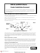
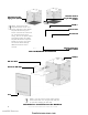
NCB-EL and NCB-FL Series Network Combiner Routers
NCB routers are Echelon network devices that, when used in pairs, allow you to connect multiple Echelon networks
in real time, spanning great distances.
These routers allow you to connect Echelon network segments isolated by great distances that cannot be spanned
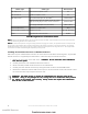
by conventional wire media. Maximum wire lengths are listed in the NCB Wiring Distance Limitations Table on
page 4 and should be considered the ABSOLUTE MAXIMUM. In many cases, where special care is not taken to
protect the specified wire from electrical noise, moisture, etc., reliable long-term operation cannot be sustained at
these wire lengths.
NCB-EL - Communication between two NCB-EL routers is via an Ethernet-to-Lonworks connection that uses
standard CAT 5 Ethernet cross-over cable.
NCB-FL - Communication between two NCB-FL routers is via an Ethernet Fiber-to-Lonworks connection that uses
dedicated fiber optic wire runs.
NCB-EL and NCB-FL Router
Product Installation Document
This document covers the procedures and specifications for installing the above listed unit(s) and when
appropriate, information regarding configuration on the monitored device. For more detailed configura-
tion and operation information, refer to the Network Installation Manual or Echelon Local Area Server
Manual as appropriate.
Ethernet Communication - EL and FL
NCB-EL and NCB-FL routers allow multiple LonWorks® networks to be connected in real-time, covering distances
from campus-wide to global; these routers use Internet Protocol (IP) for data transport. Communication between
networks via NCB router units is "live," delayed only by the transit time through the integral routers and Ethernet
channel. The NCB-EL uses standard CAT5 cross-over cable, and the NCB-FL uses dedicated fiber optic cable.
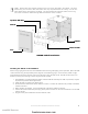
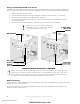
Configuring the NCB-EL/NCB-FL Router
NCB-EL/NCB-FL routers are always used in pairs (EL with EL and FL with FL) with one at each end of the Ethernet
network path. Initial router configuration is handled by a set of DIP switches on the front of each router labeled
OPTION. Switches one through six are not used; switches seven and eight are used to configure the router for the
type of network media being used: 10Base2 (not used for this application), 10BaseT (used
for the NCB-EL), or AUI (used for the NCB-FL). The NCB reads the DIP switch settings at
power-up or after you press the RESET button. These switches are used to set the following
options:
Document 51895
2/12/2002 Rev
A
51895:A ECN 01-68351895:A ECN 01-683
51895:A ECN 01-68351895:A ECN 01-683
51895:A ECN 01-683
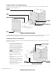
Typical Application of NCB Routers
Campus 1Campus 1
Campus 1Campus 1
Campus 1
Campus 2Campus 2
Campus 2Campus 2
Campus 2
NCBNCB
NCBNCB
NCB
RoutersRouters
RoutersRouters
Routers
Ethernet or Fiber Ethernet or Fiber
Ethernet or Fiber Ethernet or Fiber
Ethernet or Fiber
connectionconnection
connectionconnection
connection
Echelon LocalEchelon Local
Echelon LocalEchelon Local
Echelon Local
Area ServerArea Server
Area ServerArea Server
Area Server
4WRMB4WRMB
4WRMB4WRMB
4WRMB
RoutMBRoutMB
RoutMBRoutMB
RoutMB
NIONsNIONs
NIONsNIONs
NIONs
www.PDF-Zoo.com
firealarmresources.com