UniNet™ 2000 Simplex 4010 NION n o i s r e V Simplex 4010 NION Installation and Operation Manual 2 Document 51998 03/26/03 Rev 51998:A1 Technical Manuals Online! - http://www.tech-man.com firealarmresources.
This page intentionally left blank. 2 Simplex 4010 NION Installation/Operation Manual Version 2 Document 51998 Rev. A1 03/26/03 Technical Manuals Online! - http://www.tech-man.com firealarmresources.
Fire Alarm System Limitations While a fire alarm system may lower insurance rates, it is not a substitute for fire insurance! An automatic fire alarm system–typically made up of smoke detectors, heat detectors, manual pull stations, audible warning devices, and a fire alarm control with remote notification capability–can provide early warning of a developing fire. Such a system, however, does not assure protection against property damage or loss of life resulting from a fire.
Installation Precautions Adherence to the following will aid in problem-free installation with long-term reliability: WARNING - Several different sources of power can be connected to the fire alarm control panel. Disconnect all sources of power before servicing. Control unit and associated equipment may be damaged by removing and/or inserting cards, modules, or interconnecting cables while the unit is energized.
Contents Foreword .......................................................................7 Introduction................................................................................7 Section One: Simplex 4010 NION Hardware .............................................. 9 1.1: General Description ................................................................................................................ 9 1.2: Hardware Description ........................................................................
Simplex 4010 NION Installation/Operation Manual Version 2 Document 51998 Rev. A1 03/26/03 Technical Manuals Online! - http://www.tech-man.com firealarmresources.
Foreword The contents of this manual are important and must be kept in close proximity of the UniNet™ Facilities Monitoring System. If building ownership is changed, this manual and all other testing and maintenance information must also be passed to the current owner of the facility. A copy of this manual was shipped with the equipment and is also available from the manufacturer. NFPA Standards • National Fire Protection Association Standards 72 (NFPA 72). • National Electric Code (NFPA 70).
This page intentionally left blank. 8 Simplex 4010 NION Installation/Operation Manual Version 2 Document 51998 Rev. A1 03/26/03 Technical Manuals Online! - http://www.tech-man.com firealarmresources.
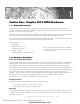
1 Section One: Simplex 4010 NION Hardware 1.1: General Description The Simplex 4010 NION interfaces to a Simplex 4010 FACP to provide monitoring of the Simplex 4010 to a UniNet™ 2000 network. The NION is based on the NION-NPB motherboard hardware and communicates with the FACP via a 4-wire EIA-232 connection. The NION to Simplex 4010 panel EIA-232 connection is handled by a Simplex 4010-9811 dual EIA-232 card. This card must be installed in the Simplex 4010 FACP for connection with a Simplex 4010 NION.
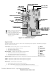
R72 Cut TTo o Disable Ground Fault Detection SMX TTransceiver ransceiver Standoff Mounting Holes Chassis Ground Power Input (TB5) TB6-Relay Output GND +24VDC BT1 3V Lithium Battery Network Communication PLCC U24 Diagnostic LEDS SW1 Reset Button TB1- 5W ire Serial 5-W Interface A SW2 Network Binding Button J1 Header for Echelon Network TTransceiver ransceiver U6 NOTE: There is a paper insulator between the battery and the battery clip installed at the factory to keep the battery charged.
NION-Simplex 4010 Connectors Power Connector (TB5) - +24VDC input power connector. TB6 - Relay output; both Normally Open/Normally Closed are available (Contacts rated at 2A 30VDC, this is a resistive load). TB1 - Standard terminal block style port for EIA-232 connection to serial channel A. Echelon Network Transceiver Connector(J1) - Pin connection header for SMX Transceiver. Reset Pin (SW1) - Resets the NION and restarts the software.
1.4: SMX Network Transceivers Connection of the network wiring to the NION is made via an SMX transceiver. The network SMX transceiver daughter board is a component of every NION. This transceiver provides the network medium interface for NION network communication. There are four styles of SMX transceivers: FTXC for FT-10 (Free Topology) wire bus and star, S7FTXC for style seven wiring requirements, FOXC for FT-10 fiber point-to-point and DFXC for bi-directional fiber.
S7FTXC-PCA (Style-7) Network Transceiver The S7FTXC-PCA combines two FT-10 interface ports that allow the transceiver to meet Style-7 wiring requirements. The two ports on the S7FTXC-PCA, when used with true style-7 wiring requirements, create a point-to-point type network segment allowing up to 8,000 feet between nodes that use the S7FTXC-PCA. The separate FT ports allow two twisted pair connections so that a cabling fault on one segment will not affect the other.
FOXC-PCA and DFXC-PCA Fiber Optic Network Transceivers The FOXC-PCA allows up to 8db of attenuation per segment in a point to point configuration only. The DFXC-PCA can operate in either a bus or a ring format. The regenerative properties of the DFXC transceiver allow runs of up to 12db of attenuation between each node, with up to 64 nodes per segment. NOTE: See Section 1.1.3 of the Network Installation manual for fiber optic cabling requirements for these transceivers.
2 Section Two: Simplex 4010 NION Installation and Configuration 2.1: Simplex 4010 NION Connection The Simplex 4010 NION provides monitoring of the Simplex 4010 FACP. This requires the use of a Simplex 4010-9811 dual EIA-232 card installed in the Simplex 4010 panel. The 4010-9811 dual EIA-232 card provides the NION the communication connection to the Simplex 4010 panel via serial port B (P6) of the 4010-9811. See figure 2-2 for wiring connections.
Serial Connections The Simplex 4010 NION requires that a Simplex model 4010-9811 dual EIA-232 card be installed in the Simplex 4010 FACP. The NION communicates to the 4010 FACP through serial port P6 onboard the 4010-9811 card. Figure 2-2 diagrams the wiring between TB1 of the NION and P6 (Serial Port B) of the 4010-9811. TB1 Simplex 4010-9811 Dual EIA-232 Card Serial PPort ort B (P6) Simplex 4010 NION NOTE: Use only wire for power limited systems.
Power Requirements and Connection The Simplex 4010 NION requires 24VDC @ 250mA nominal in accordance with local code requirements. It can be powered by any power limited, regulated source that is UL listed for use with fire protective signaling units. GND +24VDC Simplex 4010 NION Figure 2-3: Simplex 4010 NION Power Connection 2.2: Simplex 4010 NION Enclosure and Mounting For NION mounting applications where power is supplied by the monitored equipment or an external source, the NISCAB-1 should be used.
Mounting NION boards within the enclosure When installing single NION boards in this enclosure, be sure to use the inboard set of four mounting studs as shown below. Simplex 4010 NION Mounting Studs w/Standoffs Mounting Studs w/Standoffs NISCAB-1 NOTE: This enclosure must contain power limited wiring only. NOTE: Use only wire for power limited systems. Power limited wire runs use type FPLR, FPLP, FPL or equivalent cabling per NEC 760. Figure 2-5: Installing the NION in a NISCAB-1 2.
3 Section Three: Simplex 4010 NION Explorer 3.1 Simplex Explorer Overview The Simplex 4010 NION Explorer is a plug-in application that provides the ability to view panel information and NION configurations from a UniNet™ 2000 workstation. The Simplex Explorer operates much like Windows Explorer. It displays NION and Panel information in expandable menus the same way Windows Explorer displays the file system in expandable file folders. 3.2 Simplex 4010 Explorer Operation 3.2.
The Simplex 4010 Explorer Main Screen consists of the following: Update button - Saves configuration changes made with Simplex Explorer to the NION. Undo button - Cancels any configuration changes made in the plug-in. Exit button - Closes the Simplex Explorer. Arrange button - Toggles the Simplex 4010 Explorer window to be always on top or moved to the background when an event occurs. Panels tree - Displays the Simplex 4010 NION on the system and the associated Simplex 4010 panel in expandable\collapsible m
NION-Simplex 4010 Configuration Menu Learn PPanel anel Devices - This selection allows the NION to learn, or self program, all the devices associated with the Simplex 4010 panel it is connected to. This selection will start a panel learn session and the data display area will show a progress bar and the number of device types the NION has detected on the panel. When the panel learn session is complete, a message will appear. Click OK and click the Close button.
NOTE: While in Data Capture Mode, no events will be sent to the UniNet™ Workstation. NOTE: The NION requestes the Revision (REV) from the panel every 15 seconds. This is used to monitor the connection and is normal. Figure 3-5: Data Capture Mode Upload NION Configuration - This option creates a file on the hard drive containing all the information stored at the NION. This is useful to have for trouble shooting, general NION maintenance or for a backup. This file is named simplex4010_node_XXX.
Index Symbols S 2DRN Board Layout J2,J3 Pin Connections 10 J6 Pin Connections Headers for SMX Xvr 10 4010-9811 dual EIA-232 15 Fiber Optic Network Transceivers 14 fiber-optic cable 11 Serial Communication Settings 16 Serial Connections 16 Simplex 4010 NION Explorer Registering and Opening the Simplex Explorer 19 Simplex Explorer Main Form 19 Simplex Explorer Main Form 19 SMX Network Transceivers 12 DFXC-PCA 14 FOXC-PCA 14 FTXC-PCA 12 FTXC-PCB 12 S7FTXC-PCA 13 Style-7 wiring 13 M T Mounting 17 Twiste
Limited Warranty NOTIFIER® warrants its products to be free from defects in materials and workmanship for eighteen (18) months from the date of manufacture, under normal use and service. Products are date stamped at time of manufacture. The sole and exclusive obligation of NOTIFIER® is to repair or replace, at its option, free of charge for parts and labor, any part which is defective in materials or workmanship under normal use and service.