
Installation Instructions
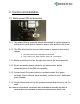

2 Control unit installation
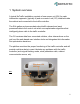
2.1 Mains power DIN rail assembly
2.1.1 The power DIN rail assembly should be installed in a place where it’s
convenient to route power cables to sensor units and the control unit.
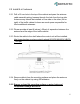
2.1.2 The DIN rail should be secured with screws to a panel in the control
cabinet
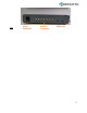
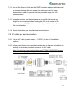
● Each SU and CU has a dedicated circuit breaker
● Color coding: Live - black, Neutral - white, PE - yellow/green.
2.1.3 Mains connection is to the far-right side, next to the surge protector.
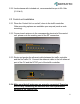
2.1.4 Route and anchor power cables for the sensor units, before
connecting them to the DIN rail assembly.
2.1.5 Connect each SU power cable to a protective earth first (green
terminal), then to Neutral (white terminal), and last to Live - dedicated
circuit breaker
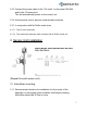
2.1.6 Connect the power cord to the protected socket and route it to the CU
shelf.
As a measure of precaution, connect the mains to the DIN rail assembly only after all
exposed cables are terminated correctly and connected to the sensor units.
4