NOVA-7820 VIA® C3 Processor CPU Embedded Board with 10/100Mbps Ethernet, VGA, Audio Version 1.0 Manual Version 1.1 Jul 16, 2003 ©Copyright 2003 by ICP Electronics Inc. All Rights Reserved.
Copyright Notice The information in this document is subject to change without prior notice in order to improve reliability, design and function and does not represent a commitment on the part of the manufacturer. In no event will the manufacturer be liable for direct, indirect, special, incidental, or consequential damages arising out of the use or inability to use the product or documentation, even if advised of the possibility of such damages.
Table of Contents 1. Introduction .................................................................. 5 1.1 1.2 Specifications ..................................................................................5 Package Contents ............................................................................6 2. Installation.................................................................... 7 2.1 2.2 2.3 2.4 2.5 2.6 2.7 NOVA-7820 Layout .....................................................................
Appendix E How to Use Video-in Function ......................... 45 Appendix F How to Use LCD-TYPE Function ........................
1. Introduction Thank you for choosing NOVA-7820 VIA® C3 Processor CPU with Multimedia & LAN Ethernet Embedded Little Board, which comes equipped with Low power VIA® C3 Processor CPU with the Intel advanced chipset 815E. This product is designed for the system manufacturers, integrators, or VARs that want to build a low power consumption system. NOVA-7820 provides on-chip VGA which provides up to 1600 x 1200 resolution. LCD which provides up to 1024 x 768 resolution.
• • • • • • • • • 1.2 1600 x 1200 in 256 Colors at 85 Hz Refresh. LCD Controller: Onboard SP1015 LCD controller. Screen Resolution: up to 1024 x 768 36bits. Intel 82801BA embedded LAN: IEEE 802.3u Auto-Negotiation support for 10BASE-T/100BASE-TX. Fast back-to-back transmission support with minimum interframe spacing. Connected to your LAN through RJ45 connector. Keyboard Controller: 8042 compatible for keyboard and PS/2 mouse 4 Digital Inputs and 4 Digital Outputs. 4 Channels of composite video input.
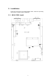
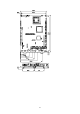
2. Installation Follow the instructions of installing NOVA-7820. Read the unpacking information carefully before installation. 2.
2.2 Clear CMOS Setup CMOS RAM holds the configuration data of NOVA-7820, which has to be set by means of system BIOS. To clear CMOS RAM, close JP1 for about 3 seconds, and then open it again. It will then resume to normal mode. • JP1: Clear CMOS Setup JP1 1-2 2-3 2.3 Description Keep CMOS Setup (Normal Operation) Clear CMOS Setup Compact Flash Setting Set the operating mode of Compact Flash disk. This is similar to the operation of hard disk. • JP2: Compact Flash Setting JP2 OPEN Close 2.
2.5 LCD Panel Shift Clock/Panel VCC Select This jumper is for the setting of LCD panel shift clock mode and panel power voltage. • JP7: LCD Panel Shift Clock JP7 1-3 3-5 • JP7: Panel VCC JP7 2-4 4-6 2.6 Description Inverted Normal Description +5V +3.3V COM Port RI and Voltage Selection JP8 is setting COM3, 4 RI and Voltage.
2.
3. Connection This chapter describes how to connect peripherals, switches and indicators to the NOVA-7820 board. The following table lists the connectors on NOVA7820.
3.1 Floppy Disk Drive Connector NOVA-7820 board is equipped with a 34-pin daisy-chain driver connector cable. • CN24: FDD Connector PIN 1 3 5 7 9 11 13 15 17 19 21 23 25 27 29 31 33 3.
3.3 Ultra ATA33/66/100 IDE Disk Drive Connector You can attach one IDE (Integrated Device Electronics) hard disk drives to the NOVA-7820 IDE controller. • CN2: Primary IDE Connector PIN 1 3 5 7 9 11 13 15 17 19 21 23 25 27 29 31 33 35 37 39 3.
3.5 USB Port Connector NOVA-7820 provides two USB ports (USB 1.1 compliant). • CN35: USB 8-PIN HEADER PIN A1 A2 A3 A4 B1 B2 B3 B4 3.6 Description VCC DATA0DATA0+ GROUND VCC DATA0DATA0+ GROUND Serial Ports NOVA-7820 offers four high speed NS16C550 compatible UARTs with Read/Receive 16 byte FIFO in each serial port.
• CN48: 10-pin Connector PIN 1 2 3 4 5 6 7 8 9 10 • CN49: 14-pin Connector PIN 1 2 3 4 5 6 7 8 9 10 11 12 13 14 3.
3.8 Keyboard Connector NOVA-7820 provides 6-PIN MIN-DIN keyboard/mouse connector. • CN16: 6-pin Mini-DIN Keyboard/Mouse Connector PIN 1 2 3 4 5 6 3.9 Description KEYBOARD DATA MOUSE DATA GROUND +5V KEYBOARD CLOCK MOUSE CLOCK IrDA Infrared Interface Port NOVA-7820 has a built-in IrDA port which supports Serial Infrared (SIR) or Amplitude Shift Keyed IR (ASKIR) interface. To use the IrDA port, set SIR or ASKIR model in COM 2 of BIOS Peripheral Setup. Then the normal RS232 COM 2 will be disabled.
3.11 Audio Connectors NOVA-7820 has a built-in AUDIO chipset (CMEDIA CMI8738LX); connector directly connects to the pin-header (CN32). The audio chipset can support 5.1 channel sounds that include LINE-OUT, REAR, and CENTER/BASS. • CN32: Audio Connector (2x8_2.
3.13 LAN RJ45 Connector NOVA-7820 is equipped with built-in one 10/100Mbps Ethernet Controller. You can connect it to your LAN through RJ45 LAN connector. The pin assignments are as following: • CN37 : Intel 82562ET LAN RJ45 Connector PIN 1 2 3 4 Description TX+ TXRX+ N/C PIN 5 6 7 8 Description N/C RXN/C N/C 3.14 Compact Flash Connector-TYPE II NOVA-7820 supports one Compact Flash socket that be provided from IDE2. You must set the jumper to avoid the conflict.
3.15 External Switches and Indicators There are several external switches and indicators for monitoring and controlling your CPU board. All the functions are in the CN7, CN12, and CN20 connectors.
3.17 CardBus/PCMCIA Connector NOVA-7820 built-in a CardBus/PCMCIA interface connector.
3.18 Digital I/O One characteristic of digital circuit is its fast response to high or low signal. This kind of response is highly needed for harsh and critical industrial operating environment. That’s why we design 4-bit digital inputs and 4-bit digital outputs on NOVA-7820. Digital Input and Output, generally, are control signals. You can use these signals to control external devices that needs On/Off circuit or TTL devices. We provide "BIOS Call" for DIO reading.
3.19 LCD Panel Connector NOVA-7820 provides a 2 x 25-pin connector for the LCD flat panel interface. NOVA-7820 supports TFT LCD panels at following display options: Video Display Type Resolution Example TFT VGA 640 x 480, 18 bits Toshiba LTM10C209H TFT SVGA 800 x 600, 18 bits Toshiba LTM12C275C TFT XVGA 1024 x 768, 18 bits L.G LM151X2 Note that the table is for reference only. The LCD panel connector of NOVA-7820 may support more panel types.
4. AMI BIOS Setup 4.1 Introduction This chapter discusses the Setup program built into the BIOS. which allows users to configure the system. This configuration is then stored in battery-backed CMOS RAM so that Setup information is retained whilst the power is off. 4.2 Starting Setup The BIOS is immediately active when you turn on the computer.
Auto Configuration with Fail Safe Settings: Load fails-safe configuration settings. Save Settings and Exit: Write the current settings to CMOS and exit. Exit Without Saving: Exit without saving the current settings. AMIBIOS HIFLEX SETUP UTILITY – VERSION 1.52 (C) 2001 American Megatrends, Inc. All Rights Reserved NOVA-7820 V1.
4.4 Standard CMOS Setup Selections AMIBIOS SETUP – STANDARD CMOS SETUP (C) 2001 American Megatrends, Inc.
Primary/Secondary Master/Slave 32Bit Mode This option enables Primary Master IDE 32-bit data transfers on the IDE data port. If disabled,16-bit data transfer is used by the BIOS.32-bit data transfers can only be enabled if IDE prefetch mode is also enabled. Boot Sector Virus Protection When this option is enabled, AMIBIOS issues a warning when any program or virus issues a Disk Format command or attempts to write to the boot sector of the hard disk drive. The settings are Disabled, or Enabled.
Quick Boot When Quick Boot is selected, DRAM testing function will be disabled. 1st Boot Device This option sets the type of device for the first boot drives that the AMIBIOS attempts to boot from after AMIBIOS POST completes. The settings are Disabled, IDE-0, IDE-1, IDE-2, IDE-3, Floppy, ARMD-FDD, ARMD-HDD, CDROM, and SCSI. 2nd Boot Device This option sets the type of device for the second boot drives that the AMIBIOS attempts to boot from after AMIBIOS POST completes.
keyboard. The settings are Absent, Present. Primary Display Select this option to configure the type of monitor attached to the computer. The settings are Monochrome, Color 40x25, Color 80x25, VGA/PGA/EGA, or Not Install. Password Check This item allows you Setup/Always Password Check. Boot To OS/2 Set this option to Enabled if running OS/2 operating system and using more than 64MB of system memory on the motherboard. The settings are Disabled or Enabled.
C800, 16k Shadow These options enable shadowing of the contents of the ROM area named in the option title. The settings are Enabled, Disabled, and Cached. The ROM area that is not used by ISA adapter cards will be allocated to PCI adapter cards. CC00, 16k Shadow These options enable shadowing of the contents of the ROM area named in the option title. The settings are Enabled, Disabled, and Cached. The ROM area that is not used by ISA adapter cards will be allocated to PCI adapter cards.
4.6 Advanced Chipset Setup Selections AMIBIOS SETUP – ADVANCED CHIPSET SETUP (C) 2001 American Megatrends, Inc. All Rights Reserved Memory Hole Disabled SDRAM Timing by SPD Disabled DRAM Refresh 15.
AGP Aperture Window This feature allows you to select the size of mapped memory for AGP graphic data. USB Function Select Enabled if your system contains a Universal Serial Bus (USB) controller and you have USB peripherals. USB Device Legacy Support This motherboard support Universal Serial Bus (USB) devices. If detected, USB controller legacy mode will be enabled. If not detected, USB controller legacy mode will be disabled.
4.7 Power Management Setup Selections AMIBIOS SETUP – POWER MANAGEMENT SETUP (C) 2001 American Megatrends, Inc.
FDC/LPT/COM Ports Enabling the option allows the IRQ input to be monitored for both inactivating for entering Auto_mode/SMI_mode and activating for entering Normal_mode. SB & MSS Audio Ports Enabling the option allows the IRQ input to be monitored for both inactivating for entering Auto_mode/SMI_mode and activating for entering Normal_mode. MIDI Ports Enabling the option allows the IRQ input to be monitored for both inactivating for entering Auto_mode/SMI_mode and activating for entering Normal_mode.
Alarm Date You can set time for date. Alarm Hour You can set time for hour. Alarm Minute You can set time for minute. Alarm Second You can set time for second. Power Type Select Select you use power type. 4.8 PCI / Plug and Play Setup Selections AMIBIOS SETUP – PCI / PLUG AND PLAY SETUP (C)2001 American Megatrends, Inc.
devices. If disabled, BIOS will configure all devices. Clear NVRAM on Every Boot When this option is set to Yes, system can auto clear NVRAM. PCI Latency Timer (PCI Clocks) This option specifies the latency timings (in PCI clocks) for PCI devices installed in the PCI expansion slots. The settings are 32, 64, 96, 128, 160, 192, 224, or 248. PCI VGA Palette Snoop If enable, PCI will allow VGA palette signals to go to the ISA bus.
4.9 Peripheral Setup Selections AMIBIOS SETUP – PERIPHERAL SETUP (C) 2001 American Megatrends, Inc.
OnBoard FDC Set this option to Enabled to enable the floppy drive controller on the motherboard. The settings are Auto (AMIBIOS automatically determines if the floppy controller should be enabled), Enabled, or Disabled. OnBoard Serial PortA/B This option specifies the base I/O port address of serial port A. The settings are Auto (AMIBIOS automatically determines the correct base I/O port address), Disabled, 3F8h, 2F8h, 2E8h, or 3E8h.
4.10 Hardware Monitor Setup Selections AMIBIOS SETUP – HARDWARE MONITOR SETUP (C) 2001 American Megatrends, Inc. All Rights Reserved CPU Temperature System Temperature CPU Fan Speed Chassis Fan Speed Vcore Vtt + 3.3V + 5.0V +12.0V +5V SB 31ºC/87ºF 29ºC/84ºF 6300 RPM 0 RPM 1.399 V 1.501 V 3.349 V 5.070 V 12.046 V 4.978 V ESC: Exit : Sel PgUp/PgDn: Modify F1: Help F2/F3: Color Figure 8: Hardware Monitor Setup This setup helps users monitor NOVA-7820 board on board system voltage and fan speed.
Appendix A Watchdog Timer Watchdog Timer is a device to ensure that standalone systems can always recover from catastrophic conditions that cause CPU crash which may be caused by external EMI or a software bug. When the CPU stops working normally, hardware on the board will issue a time-out signal.
Appendix B Digital I/O One characteristic of digital circuit is its fast response to high or low signal. This kind of response is highly needed for harsh and critical industrial operating environment. That’s why we design 4-bit digital inputs and 4-bit digital outputs on the NOVA-7820. Digital Input and Output, generally, are control signals. You can use these signals to control external devices that needs On/Off circuit or TTL devices.
Appendix C Address Mapping IO Address Map I/O address Range 000-01F 020-021 02E-02F 040-05F 04E-04F 060-06F 070-07F 080-09F 0A0-0BF 0C0-0DF 0F0 0F1 0F2 0F8-0FF 1F0-1F8 295-296 2E8-2EF 2F8-2FF 300-31F 360-36F 378-37F 3B0-3BF 3C0-3CF 3D0-3DF 3E8-3EF 3F0-3F7 3F8-3FF Description DMA Controller #1 Interrupt Controller #1, Master Super I/O 8254 timer Super I/O 8042 (Keyboard Controller) Real time Clock, NMI Mask DMA Page Register Interrupt Controller #2 DMA Controller #2 Clear Math Coprocessor Busy Reset Math Co
IRQ Mapping Table IRQ0 IRQ1 IRQ2 IRQ3 IRQ4 IRQ5 IRQ6 IRQ7 System Timer IRQ8 RTC clock Keyboard IRQ9 Available Cascade to IRQ Controller IRQ10 COM4 COM2 IRQ11 COM3 COM1 IRQ12 PS/2 mouse Audio Device IRQ13 FPU FDC IRQ14 Primary IDE Printer IRQ15 Secondary IDE DMA Channel Assignments Channel 0 1 2 3 4 5 6 7 Function Available Available Floppy disk (8-bit transfer ) Available Cascade for DMA controller 1 Available Available Available 43
Appendix D How to Use Wake-up Function NOVA-7820 provides two kind of Wake up Function. This page describes how to use Modem Wake-Up and LAN Wake-Up function. Wake-Up function is working while you use ATX power supply. Wake-Up By Ring: You must set the option Power On By Ring of CMOS SETUP to be enabled. The ATX power supply will be switched on when there is a ring signal detected on pin “RI” of serial port.
Appendix E How to Use Video-in Function NOVA-7820 provides users to capture live video from video source such as the CCTV camera. NOVA-7820 has four video input channels for surveillance systems. Driver Installation: Taking the advantage of IEI driver installation program makes the driver installation an easy job. Steps: 1. Insert the IEI Driver CD (4). 2. The window will display the menu of IEI Driver CD. Click “IVC Series”. 3. Click “IVC-100/100G/200/200G”. 4. Double click the “Windows” folder. 5.
Pin Definition: Dupont Head 8-pin PIN 1 3 5 7 Description AVIN0 AVIN1 AVIN2 AVIN3 PIN 2 4 6 8 Description GROUND GROUND GROUND GROUND D-SUB 9-pin (for both cable 1 and cable 2) PIN 1 3 5 7 9 Description AVIN0 AVIN2 N.C. GROUND GROUND PIN 2 4 6 8 Description AVIN1 AVIN3 GROUND GROUND Cable 2: D-SUB 9-pin, connected to cable 1. RCA connectors are used to connect with video-in source.
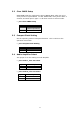
Appendix F How to Use LCD-TYPE Function NOVA-7820 provides four kind of LCD-TYPE Function. This page describes how to use LCD-TYPE function. LCD-TYPE function Procedure: 1. Go to the DOS command prompt in MS-DOS or Windows 9x. 2. At the DOS command prompt, type "LCD_Prg". 3. Then you can set 1,2,3,4 from LCD Type. ICP Electronic Inc. LCD Module Flash Utility 640x480 18 bits 800x600 18 bits 1024x768 18 bits 1024x768 36 bits [M]Menu [1-4] LCD Type [ESC]Exit 4. Reboot the system.